Table of Contents
Advertisement
Quick Links
This insert can be used in the following
mantel and fireplace systems:
FBNSD400T-A-(AS,CH)
HNS400T-MV-(WC,AS)
WARNING: If the information in this manual is not
followed exactly, a fire or explosion may result causing
property damage, personal injury or loss of life.
— Do not store or use gasoline or other flammable va-
pors and liquids in the vicinity of this or any other
appliance.
— WHAT TO DO IF YOU SMELL GAS
• Do not try to light any appliance.
• Do not touch any electrical switch; do not use any
phone in your building.
• Immediately call your gas supplier from a neighbor's
phone. Follow the gas supplier's instructions.
• If you cannot reach your gas supplier, call the fire
department.
— Installation and service must be performed by a quali-
fied installer, service agency or the gas supplier.
WARNING: This appliance is equipped for natural and
propane gas. Field conversion is not permitted other
than between natural or propane gases.
Questions, problems, missing parts? Before returning to your retailer, call
our customer service department at 1-866-573-0674, 8:00 am - 4:30 pm CST,
Monday through Friday or email contact@usaprocom.com
VENT-FREE GAS SYSTEM
OWNER'S OPERATION
AND INSTALLATION
MANUAL
MODELS
FBNSD400T-ZC SERIES
PFS
®
US
Advertisement
Table of Contents

Subscribe to Our Youtube Channel
Related Manuals for Procom FBNSD400T-ZC Series


Summary of Contents for Procom FBNSD400T-ZC Series
- Page 1 VENT-FREE GAS SYSTEM OWNER'S OPERATION AND INSTALLATION MANUAL MODELS FBNSD400T-ZC SERIES This insert can be used in the following ® mantel and fireplace systems: FBNSD400T-A-(AS,CH) HNS400T-MV-(WC,AS) WARNING: If the information in this manual is not followed exactly, a fire or explosion may result causing property damage, personal injury or loss of life.
-
Page 2: Table Of Contents
* Aftermarket: Completion of sale, not for purpose of resale, from the manufacturer. PROCOM HEATING, INC. PATENT INFORMATION This product may be covered by one or more of the following United States patents:... -
Page 3: Safety
SAFETY WARNING: Do not attempt to DANGER: Carbon monoxide access or change the setting of poisoning may lead to death! the fuel selection means. Carbon Monoxide Poisoning: Early signs Access to and adjustment of of carbon monoxide poisoning resemble the the fuel selection means must flu, with headaches, dizziness or nausea. - Page 4 SAFETY 6. Do not run heater: WARNING: Do not place • Where flammable liquids or vapors are clothing or other flammable used or stored. • Under dusty conditions. material on or near the appliance. 7. Before using furniture polish, wax, carpet Never place any objects in the cleaner, or similar products, turn heater off.
-
Page 5: Specifications
SPECIFICATIONS FBNSD400T-ZC Gas Type Natural Propane Maximum Input Rating 32,000 BTU/Hr 32,000 BTU/Hr Minimum Input Rating 14,500 BTU/Hr 24,500 BTU/Hr Regulator Pressure Setting 4" W.C. 9" W.C. Inlet Gas Pressure* Max. 9.5" W.C. Max. 14" W.C. (inches of water) Min. 5" W.C. Min. -
Page 6: Product Identification
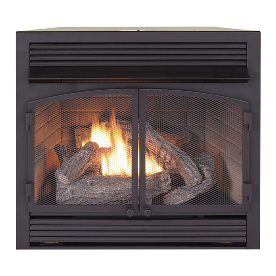
PRODUCT IDENTIFICATION Hood Screen Logs Heater Controls (Inside Panel) Figure 1 - Vent-Free Fireplace Insert UNPACKING 1. Remove top inner pack. 6. Hold the screen, lift, and pull forward. 2. Tilt carton so that heater is upright. 7. Remove log set by cutting plastic ties. 3. -
Page 7: Water Vapor: A By-Product Of Unvented Room Heaters
WATER VAPOR: A BY-PRODUCT OF UNVENTED ROOM HEATERS Water vapor is a by-product of gas combus- The following steps will help ensure that water tion. An unvented room heater produces ap- vapor does not become a problem. proximately one (1) ounce (30 mL) of water 1. - Page 8 AIR FOR COMBUSTION AND VENTILATION VENTILATION AIR Ventilation Air From Outdoors Provide extra fresh air by using ventilation Ventilation Air From Inside Building grills or ducts. You must provide two perma- This fresh air would come from an adjoining nent openings: one within 12" of the ceiling unconfined space.
-
Page 9: Installation
INSTALLATION NOTICE: This heater is intended WARNING: Never install the for use as supplemental heat. heater Use this heater along with your • in a bedroom or bathroom primary heating system. Do not • in a recreational vehicle install this heater as your pri- •... - Page 10 INSTALLATION GAS SELECTION Insert Gas Fitting Insert Gas Fitting This appliance is factory for Propane Gas for Natural Gas preset for propane gas. No changes are required for connecting to propane. Only a qualified installer or service technician can perform gas se- lection and connecting to gas supply.
- Page 11 INSTALLATION Use only the cap supplied on the Brass regulator. Do not use an off the Fitting shelf pipe plug. This can damage the plunger. The supplied regula- tor cap is designed so it will not engage the unused gas type. 3.
- Page 12 Measure from outermost point of heater. Note: This firebox can not be installed in an existing fireplace. Install this firebox only in a ProCom Heating, Inc. mantel accessory approved for this product. Minimum Clearances For Side Combustible Material, Side Wall...
- Page 13 INSTALLATION 1. Frame in rough opening. Use dimensions IMPORTANT: When finishing your firebox, shown in Figure 7 for the rough opening. combustible materials such as wall board, If installing in a corner, use dimensions gypsum board, sheet rock, drywall, plywood, shown in Figure 9, for the rough opening.
- Page 14 INSTALLATION CONNECTING TO GAS SUPPLY WARNING: A qualified ser- CAUTION: For natural gas, vice technician must connect check your gas line pressure heater to gas supply. Follow all before connecting heater to gas local codes. line. Gas line pressure must be no greater than 9.5"...
- Page 15 INSTALLATION Typical Inlet Pipe Diameters ing gas pressure, heater regulator damage Use 3/8" black iron pipe or greater. Installa- could occur. Install external regulator with the tion must include an equipment shutoff valve, vent pointing down as shown in Figure 12. union, and plugged 1/8"...
- Page 16 INSTALLATION CHECKING GAS CONNECTIONS Open Equipment WARNING: Test all gas piping Shutoff Valve and connections, internal and external to unit, for leaks after installing or servicing. Correct Closed all leaks at once. Figure 13 - Equipment Shutoff Valve Equipment WARNING: Never use an open Propane Shutoff Valve Supply Tank...
- Page 17 INSTALLATION INSTALLING LOGS Slots in Rear Plate WARNING: Failure to posi- tion the parts in accordance with these diagrams or failure to use only parts specifically approved with this heater may result in property damage or personal injury. CAUTION: After installation and periodically thereafter, Log #1 check to ensure that no yellow...
- Page 18 INSTALLATION 4. Install pins on log #4 onto the two slots 6. Insert the pin on log #6 into the hole on in the front bracket (see Figure 16 and log #3 (see Figures 18 and 19). Figure 18). IMPORTANT: Make sure logs do not cover 5.
-
Page 19: Operation
OPERATION FOR YOUR SAFETY READ BEFORE LIGHTING not use any phone in your building. WARNING: If you do not fol- • Immediately call your gas supplier low these instructions exactly, from a neighbor’s phone. Follow the a fire or explosion may result gas supplier’s instructions. - Page 20 OPERATION 7. With control knob pressed in, push 11. If heater will not operate, follow the in- down and release ignitor button. This structions To Turn Off Gas To Appliance, will light pilot. The pilot is attached to and call your service technical or gas the rear of the burner.
-
Page 21: Inspecting Burners
INSPECTING BURNERS IMPORTANT: Owner’s should check pilot flame pattern and burner flame pattern often. Incorrect flame patterns indicate the need for cleaning (see Care and Maintenance, page 22) or service. WARNING: Only a qualified service person should service and repair heater. This includes maintenance requiring replacement or alteration of components. -
Page 22: Care And Maintenance
CARE AND MAINTENANCE WARNING: Turn off heater and let cool before servicing. CAUTION: You must keep control areas, burner, and circulating air passageways of heater clean. Inspect these areas of heater before each use. Have heater inspected yearly by a qualified service techni- cian. - Page 23 CARE AND MAINTENANCE ODS/PILOT Ignitor Natural Gas Thermocouple CAUTION: Never use a wire, Electrode Burner needle, or similar object to clean Propane Gas Burner ODS/pilot. This can damage ODS/pilot unit. Use a vacuum cleaner, pressurized air, or a Pilot Air small, soft bristled brush to clean.
-
Page 24: Troubleshooting
TROUBLESHOOTING WARNING: If you smell gas: • Shut off gas supply. • Do not try to light any appliance. • Do not touch any electrical switch; do not use any phone in your building. • Immediately call your gas supplier from a neighbor’s phone. Fol- low the gas supplier’s instructions. - Page 25 TROUBLESHOOTING Problem Possible Cause Corrective Action When ignitor button is 1. Low battery. 1. Replace battery. pressed in, there is no 2. Ignitor electrode is not 2. Replace ignitor cable. spark at ODS/pilot. connected to ignitor cable. 3. Ignitor cable is pinched or 3.
- Page 26 TROUBLESHOOTING Problem Possible Cause Corrective Action Burner does not light after 1. Burner orifice is clogged. 1. Clean burner orifice (see ODS/pilot is lit. Care and Maintenance, page 22). 2. Inlet gas pressure is too low. 2. Contact local gas supplier. 3.
- Page 27 TROUBLESHOOTING Problem Possible Cause Corrective Action H e a t e r p r o d u c e s a 1. Turning control knob to high 1. Turn control knob to low whistling noise when position when burner is cold. position and let warm up for burner is lit.
-
Page 28: Parts
PARTS MODEL FBNSD400T-ZC www.usaprocom.com 200348-01C... - Page 29 PARTS MODEL FBNSD400T-ZC This list contains replaceable parts used in your heater. When ordering parts, follow the instructions listed under Replacement Parts on page 30 of this manual. ITEM PART # DESCRIPTION 161818-01HT Hood 161368-01HT Left Door Assembly 161369-01HT Right Door Assembly 161822-01 Gas Train Assembly 161338-01...
-
Page 30: Replacement Parts
1-866-573-0674 for referral information. ACCESSORIES Purchase these heater accessories from your local dealer. If they can not supply these ac- cessories, contact ProCom Heating, Inc. at 1-866-573-0674 for information. EQUIPMENT SHUTOFF VALVE For all models. Equipment shutoff valve with 1/2" NPT tap. -
Page 31: Service Hints
You may feel your gas pressure is too low. If so, contact your local gas supplier. TECHNICAL SERVICE You may have further questions about installation, operation, or troubleshooting. If so, contact ProCom Heating, Inc. at 1-866-573-0674. When calling, please have your model and serial numbers of your heater ready. www.usaprocom.com... -
Page 32: Warranty
We make no other warranty, expressed or implied. NEW PRODUCTS Standard Warranty: ProCom Heating, Inc. warrants this product to be free from defects in materials and components for ONE (1) year from the date of first purchase, provided that the product has been properly installed by a qualified installer in accordance with all local codes and instructions furnished with the unit, operated and maintained in accordance with all applicable instructions.
Need help?
Do you have a question about the FBNSD400T-ZC Series and is the answer not in the manual?
Questions and answers