Table of Contents
Advertisement
WARNING: If the information in this manual is not
followed exactly, a fire or explosion may result causing
property damage, personal injury or loss of life.
— Do not store or use gasoline or other flammable va-
pors and liquids in the vicinity of this or any other
appliance.
— WHAT TO DO IF YOU SMELL GAS
• Do not try to light any appliance.
• Do not touch any electrical switch; do not use any
phone in your building.
• Immediately call your gas supplier from a neighbor's
phone. Follow the gas supplier's instructions.
• If you cannot reach your gas supplier, call the fire
department.
— Installation and service must be performed by a quali-
fied installer, service agency or the gas supplier.
WARNING: This appliance is equipped for Natural and
Propane gas. Field conversion is not permitted other than
between natural or propane gases.
Questions, problems, missing parts? Before returning to your retailer, call
our customer service department at 1-866-573-0674, 8:00 am - 4:30 pm CST,
Monday through Friday or email customerservice@usaprocom.com
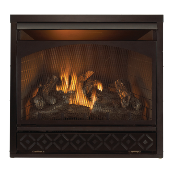
VENT-FREE GAS
FIREPLACE INSERT
OWNER'S OPERATION AND
INSTALLATION MANUAL
MODEL FBD32RT
PFS
®
US
Advertisement
Table of Contents

Related Manuals for Procom FBD32RT


Summary of Contents for Procom FBD32RT
- Page 1 VENT-FREE GAS FIREPLACE INSERT OWNER’S OPERATION AND INSTALLATION MANUAL MODEL FBD32RT ® WARNING: If the information in this manual is not followed exactly, a fire or explosion may result causing property damage, personal injury or loss of life. — Do not store or use gasoline or other flammable va- pors and liquids in the vicinity of this or any other appliance.
-
Page 2: Table Of Contents
TABLE OF CONTENTS Safety ............3 Air For Combustion and Ventilation ... 7 Specifications ..........4 Installation ..........10 Qualified Installing Agency ......5 Operation ..........20 Product Features ........5 Inspecting Burners........24 Local Codes..........5 Care And Maintenance ......25 Unpacking.......... -
Page 3: Safety
SAFETY IMPORTANT: Read this owner’s WARNING: Any change to manual carefully and completely this fireplace or its controls can before trying to assemble, op- be dangerous. erate, or service this heater. Improper use of this heater can WARNING: Do not allow fans cause serious injury or death to blow directly into fireplace. -
Page 4: Specifications
Poor combustion and higher levels of carbon monoxide may result. SPECIFICATIONS Model FBD32RT Gas Type Natural Gas Propane Gas Ignition Piezo Ignitor... -
Page 5: Qualified Installing Agency
QUALIFIED INSTALLING AGENCY Only a qualified agency should install and a) Installing, testing, or replacing gas piping replace gas piping, gas utilization equipment or accessories, and repair and equipment ser- b) Connecting, installing, testing, repairing, vicing. The term “qualified agency” means any or servicing equipment;... -
Page 6: Unpacking
UNPACKING 1. Remove top inner pack. 7. Remove log set by cutting plastic ties. 2. Tilt carton so that heater is upright. 8. Carefully unwrap log. 3. Remove protective side packaging. 9. Check for any shipping damage. If heater or log is damaged, promptly inform your 4. -
Page 7: Air For Combustion And Ventilation
AIR FOR COMBUSTION AND VENTILATION heat loss in homes. Home owners weather WARNING: This heater shall strip and caulk around windows and doors not be installed in a confined space to keep the cold air out and the warm air in. or unusually tight construction During heating months, home owners want their homes as airtight as possible. - Page 8 AIR FOR COMBUSTION AND VENTILATION DETERMINING FRESH-AIR FLOW FOR HEATER LOCATION Determining if You Have a Confined or Unconfined Space Use this work sheet to determine if you have 4. Compare the maximum Btu/Hr the space a confined or unconfined space. can support with the actual amount of Btu/ Hr used.
-
Page 9: Ventilation Air From Inside Building
AIR FOR COMBUSTION AND VENTILATION VENTILATION AIR Ventilation Air From Inside Building This fresh air would come from an adjoining 1 and 2, Figure 2). You can also remove door unconfined space. When ventilating to an into adjoining room (see option 3, Figure 2). adjoining unconfined space, you must provide Follow the National Fuel Gas Code, ANSI two permanent openings: one within 12"... -
Page 10: Installation
INSTALLATION IMPORTANT: Vent-free heaters add moisture NOTICE: This heater is intended to the air. Although this is beneficial, installing for use as supplemental heat. heater in rooms without enough ventilation air Use this heater along with your may cause mildew to form too much moisture. primary heating system. -
Page 11: Gas Supply
INSTALLATION GAS SELECTION must be locked in the NG position. Do not This appliance is factory operate heater between locked positions! preset for propane/LP gas. 3. Rotate and close cover over fuel selection No changes are required for device and reinstall screw. connecting to propane/LP. - Page 12 INSTALLATION BUILT-IN FIREPLACE INSTALLATION WARNING: Do not allow any combustible materials to overlap the firebox front. WARNING: Do not allow combustible or noncombustible 3/4" Clearance to Facia materials to cover any necessary " Clearance to Sides, Back and Top openings like louvered slots. "...
-
Page 13: Installing Hood
INSTALLATION 3. Attach gas line to fireplace gas regulator. See Connecting to Gas Supply, page 14. 4. Check all gas connections for leaks. See Checking Gas Connections, page 16. " IMPORTANT: When finishing your firebox, combustible materials such as wall board, gypsum board, sheet rock, drywall, plywood, etc, must have 1/2"... - Page 14 INSTALLATION CONNECTING TO GAS SUPPLY WARNING: A qualified ser- CAUTION: For propane/ LP gas, never connect heater vice technician must connect directly to the gas supply. This heater to gas supply. Follow all heater requires an external local codes. regulator (not supplied). Install WARNING: This appliance the external regulator between requires a 3/8"...
- Page 15 INSTALLATION For propane/LP installations, apply pipe external regulator with the vent pointing down joint sealant lightly to male threads. This will as shown in Figure 13. Pointing the vent down prevent excess sealant from going into pipe. protects it from freezing rain or sleet. Excess sealant in pipe could result in clogged Install sediment trap in supply line as shown heater valves.
-
Page 16: Checking Gas Connections
INSTALLATION CHECKING GAS CONNECTIONS 2. Pressurize supply piping system by either WARNING: Test all gas piping opening propane/LP supply tank valve and connections for leaks after for propane/LP gas or opening main gas installing or servicing. Correct valve located on or near gas meter for natural gas or using compressed air. - Page 17 INSTALLATION 4. Check all joints from equipment shutoff 6. Light heater (see Lighting Instructions on valve to control valve (see Figure 16 or page 20). Check all other internal joints 17, page 16). Apply a noncorrosive leak for leaks. detection fluid to all joints. Bubbles form- 7.
- Page 18 INSTALLATION INSTALLING LOGS Each log is marked with a number. This WARNING: Failure to posi- number will help you to identify the logs when tion the parts in accordance installing. with these diagrams or failure After installing logs, add decorative cinders around the grate base, do not place any to use only parts specifically decorative cinders on logs or burner.
- Page 19 INSTALLATION INSTALLING BATTERIES Receiver and Remote Control CAUTION: Do not mix old and Batteries are required in both the Remote new batteries. Do not mix alka- Control (Transmitter) (2 AAA size) and Re- ceiver (4 AA size) (see Figure 23). line, standard (carbon - zinc), or Note: Be sure batteries are placed correctly.
-
Page 20: Operation
OPERATION FOR YOUR SAFETY READ BEFORE LIGHTING not use any phone in your building. WARNING: If you do not fol- • Immediately call your gas supplier low these instructions exactly, a from a neighbor’s phone. Follow the fire or explosion may result caus- gas supplier’s instructions. -
Page 21: To Turn Off Gas To Appliance
OPERATION • If control knob does not pop up when 10. Press the LEARN BUTTON on the front released, contact a qualified service of the remote receiver box until you hear technician or gas supplier for repairs. a beep (see page 21). 7. -
Page 22: Remote Control System
OPERATION REMOTE CONTROL SYSTEM Programming the Remote and Receiver Key Settings ON - Operates unit to on position, manually The remote and receiver must be “learned” to one another. operated solenoid ON. 1. Turn control knob on the heater to the ON OFF - Operates unit to off position, manually position. - Page 23 OPERATION Setting°F/°C Scale 2. Press and hold the SET key until the de- The factory setting for temperature is °F. To sired set temperature is reached. The LCD change this setting to °C, press the ON key screen set numbers will increase from 45° and the OFF key on the remote control at the to 99°...
-
Page 24: Inspecting Burners
INSPECTING BURNERS IMPORTANT: Owner’s should check pilot flame pattern and burner flame pattern often. Incorrect flame patterns indicate the need for cleaning (see Care and Maintenance, page 25) or service. WARNING: Only a qualified service person should service and repair heater. This includes maintenance requiring replacement or alteration of components. -
Page 25: Care And Maintenance
CARE AND MAINTENANCE WARNING: Turn off heater and let cool before servicing. CAUTION: You must keep control areas, burner, and circulating air passageways of heater clean. Inspect these areas of heater before each use. Have heater inspected yearly by a qualified service techni- cian. -
Page 26: Troubleshooting
CARE AND MAINTENANCE ODS/PILOT Use a vacuum cleaner, pressurized air, or a Ignitor Electrode small, soft bristled brush to clean. Natural Gas Thermocouple A yellow tip on the pilot flame indicates dust Burner and dirt in the pilot assembly. There is a small Propane/LP pilot air inlet hole about 2"... - Page 27 TROUBLESHOOTING Problem Possible Cause Corrective Action When ignitor button is 1. Ignitor electrode is posi- 1. Replace electrode. pressed in, there is no tioned wrong. Ignitor elec- spark at ODS/pilot trode is broken. 2. Ignitor electrode is not con- 2. Replace ignitor cable nected to ignitor cable.
- Page 28 TROUBLESHOOTING Problem Possible Cause Corrective Action Burner(s) does not light 1. Burner orifice is clogged. 1. Clean burner orifice (see after ODS/pilot is lit Care and Maintenance, page 25) or replace burner orifice. 2. Burner orifice diameter is too 2. Replace burner orifice. small.
-
Page 29: Replacement Parts
TROUBLESHOOTING Problem Possible Cause Corrective Action White powder residue 1. When heated, the vapors 1. Turn heater off when using forming within burner from furniture polish, wax, furniture polish, wax, carpet box or on adjacent walls carpet cleaners, etc., turn cleaner or similar products. -
Page 30: Parts
PARTS MODEL FBD32RT TEMP 25 19 www.usaprocom.com 200069-01A... - Page 31 PARTS MODEL FBD32RT This list contains replaceable parts for your heater. When ordering replacement parts, follow the instructions listed under Replacement Parts on page 29 of this manual. ITEM PART # DESCRIPTION FB32D600 Burner Assembly YDF06-FBD32RT Fuel Selection Device MDL304B...
-
Page 32: Warranty
We make no other warranty, expressed or implied. LIMITED WARRANTY ProCom Heating, Inc. warrants this product to be free from defects in materials and components for TWO (2) years from the date of first purchase, provided that the product has been properly installed by a qualified installer in accordance with all local codes and instructions furnished with the unit, operated and maintained in accordance with all applicable instructions.
Need help?
Do you have a question about the FBD32RT and is the answer not in the manual?
Questions and answers