Table of Contents
Advertisement
WARNING: If the information in this manual is not
followed exactly, a fire or explosion may result causing
property damage, personal injury or loss of life.
— Do not store or use gasoline or other flammable va-
pors and liquids in the vicinity of this or any other
appliance.
— WHAT TO DO IF YOU SMELL GAS
• Do not try to light any appliance.
• Do not touch any electrical switch; do not use any
phone in your building.
• Immediately call your gas supplier from a neighbor's
phone. Follow the gas supplier's instructions.
• If you cannot reach your gas supplier, call the fire
department.
— Installation and service must be performed by a quali-
fied installer, service agency or the gas supplier.
WARNING: This appliance is equipped for Natural and
Propane gas. Field conversion is not permitted other than
between natural or propane gases.
Questions, problems, missing parts? Before returning to your retailer, call
our customer service department at 1-866-573-0674, 8:00 am - 4:15 pm CST,
Monday through Friday or email customerservice@usaprocom.com
VENT-FREE GAS
FIREPLACE INSERT
OWNER'S OPERATION AND
INSTALLATION MANUAL
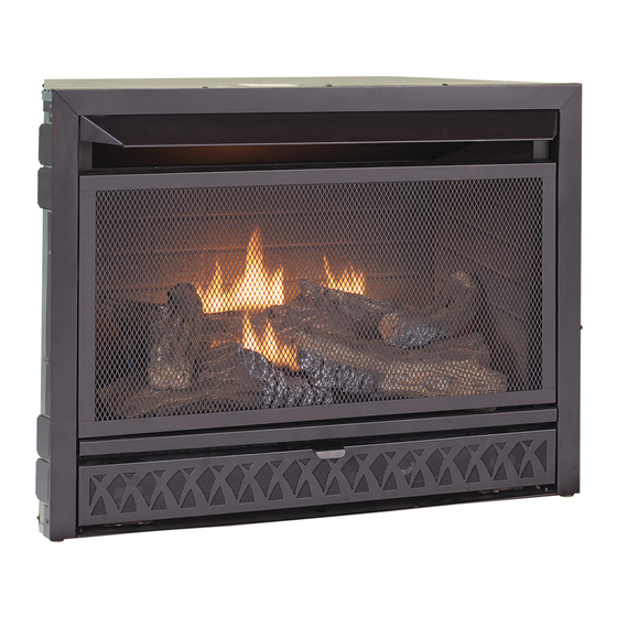
MODEL FBD28T
PFS
®
US
Advertisement
Table of Contents

Subscribe to Our Youtube Channel
Related Manuals for Procom FBD28T


Summary of Contents for Procom FBD28T
- Page 1 VENT-FREE GAS FIREPLACE INSERT OWNER’S OPERATION AND INSTALLATION MANUAL MODEL FBD28T ® WARNING: If the information in this manual is not followed exactly, a fire or explosion may result causing property damage, personal injury or loss of life. — Do not store or use gasoline or other flammable va- pors and liquids in the vicinity of this or any other appliance.
-
Page 2: Table Of Contents
TABLE OF CONTENTS Safety ............3 Operation ..........18 Specifications ..........4 Inspecting Burners........20 Qualified Installing Agency ......5 Care And Maintenance ......21 Product Features ........5 Troubleshooting ........23 Local Codes..........5 Parts ............26 Unpacking..........6 Replacement Parts ........ -
Page 3: Safety
SAFETY IMPORTANT: Read this owner’s WARNING: Any change to manual carefully and completely this heater or its controls can before trying to assemble, op- be dangerous. erate, or service this heater. Improper use of this heater can WARNING: Do not allow fans cause serious injury or death to blow directly into fireplace. -
Page 4: Specifications
Poor combustion and higher levels of carbon monoxide may result. SPECIFICATIONS Model FBD28T Gas Type Natural Gas Propane Gas Ignition Piezo Ignitor... -
Page 5: Qualified Installing Agency
QUALIFIED INSTALLING AGENCY Only a qualified agency should install and a) Installing, testing, or replacing gas piping replace gas piping, gas utilization equipment or accessories, and repair and equipment ser- b) Connecting, installing, testing, repairing, vicing. The term “qualified agency” means any or servicing equipment;... -
Page 6: Unpacking
UNPACKING 1. Remove top inner pack. 7. Remove log set by cutting plastic ties. 2. Tilt carton so that heater is upright. 8. Carefully unwrap log. 3. Remove protective side packaging. 9. Check for any shipping damage. If heater or log is damaged, promptly inform your 4. -
Page 7: Air For Combustion And Ventilation
AIR FOR COMBUSTION AND VENTILATION heat loss in homes. Home owners weather WARNING: This heater shall strip and caulk around windows and doors not be installed in a confined space to keep the cold air out and the warm air in. or unusually tight construction During heating months, home owners want their homes as airtight as possible. - Page 8 AIR FOR COMBUSTION AND VENTILATION DETERMINING FRESH-AIR FLOW FOR HEATER LOCATION Determining if You Have a Confined or Unconfined Space Use this work sheet to determine if you have 4. Compare the maximum Btu/Hr the space a confined or unconfined space. can support with the actual amount of Btu/ Hr used.
-
Page 9: Ventilation Air From Inside Building
AIR FOR COMBUSTION AND VENTILATION VENTILATION AIR Ventilation Air From Inside Building This fresh air would come from an adjoining 1 and 2, Figure 2). You can also remove door unconfined space. When ventilating to an into adjoining room (see option 3, Figure 2). adjoining unconfined space, you must provide Follow the National Fuel Gas Code, ANSI two permanent openings: one within 12"... -
Page 10: Installation
INSTALLATION IMPORTANT: Vent-free heaters add moisture NOTICE: This heater is intended to the air. Although this is beneficial, installing for use as supplemental heat. heater in rooms without enough ventilation air Use this heater along with your may cause mildew to form too much moisture. primary heating system. -
Page 11: Gas Supply
INSTALLATION Gas Selection sition (see Figure 5). Fuel selection device This appliance is factory must be locked in the NG position. Do not preset for propane/LP gas. operate heater between locked positions! No changes are required for 3. Rotate and close cover over fuel selection connecting to propane/LP. -
Page 12: 2 Www.usaprocom.com
INSTALLATION BUILT-IN FIREPLACE INSTALLATION WARNING: Do not allow any combustible materials to overlap the firebox front. WARNING: Do not allow combustible or noncombustible 3/4" Clearance to Facia materials to cover any necessary " Clearance to Sides, Back and Top openings like louvered slots. "... - Page 13 INSTALLATION 3. Attach gas line to fireplace gas regulator. See Connecting to Gas Supply, page 14. 4. Check all gas connections for leaks. See Checking Gas Connections, page 16. IMPORTANT: When finishing your firebox, combustible materials such as wall board, gypsum board, sheet rock, drywall, plywood, etc, must have 1/2"...
- Page 14 INSTALLATION CONNECTING TO GAS SUPPLY WARNING: A qualified ser- CAUTION: Avoid damage to vice technician must connect regulator. Hold gas regulator heater to gas supply. Follow all with wrench when connecting local codes. into gas piping and/or fittings. WARNING: This appliance CAUTION: Use pipe joint requires a 3/8"...
- Page 15 INSTALLATION The installer must supply an external regula- Install sediment trap in supply line as shown tor. The external regulator will reduce incom- in Figure 12. Place sediment trap where it is ing gas pressure. You must reduce incoming within reach for cleaning. Place sediment trap gas pressure to between 11"...
-
Page 16: Checking Gas Connections
INSTALLATION CHECKING GAS CONNECTIONS Test Pressures Equal To or Less Than WARNING: Test all gas piping 1/2 PSIG (3.5 kPa) and connections for leaks after 1. Close equipment shutoff valve (see Fig- installing or servicing. Correct ure 15). all leaks at once. 2. -
Page 17: Installing Logs
INSTALLATION PRESSURE TESTING HEATER GAS CONNECTIONS 1. Open equipment shutoff valve (see Figure 17, page 16). Apply a noncorrosive leak 15, page 16). detection fluid to all joints. Bubbles form- ing show a leak. 2. Open main gas valve located on or near gas meter for natural gas or open pro- 5. -
Page 18: Operation
INSTALLATION BATTERY INSTRUCTIONS Unscrew ignitor cap and install a AAA battery CAUTION: Do not mix old and with the + pointing out. Replace cap. new batteries. Do not mix alka- line, standard (carbon - zinc), or rechargeable (nickel - cadmium) batteries. -
Page 19: Lighting Instructions
OPERATION LIGHTING INSTRUCTIONS Note: If pilot does not stay lit, refer to WARNING: You must oper- Troubleshooting, pages 23 though 25. ate this heater with the screen Also contact a qualified service technician in place. Make sure screen is or gas supplier for repairs. Until repairs are made, light pilot with match. -
Page 20: Inspecting Burners
OPERATION THERMOSTAT CONTROL OPERATION The thermostatic control used on this model room temperature drops below the set tem- differs from standard thermostats. Standard perature. The control knob can be set to any thermostats simply turn the burner on and off. comfort level between HIGH (5) and LOW (1). -
Page 21: Care And Maintenance
INSPECTING BURNERS Approx. 3"-6" Above Top of Logs Figure 22 - Correct Pilot Flame Pattern Figure 23 - Incorrect Pilot Flame Pattern (Natural Gas shown) (Natural Gas shown) BURNER FLAME PATTERN Figure 24 shows a correct burner flame pattern. Figure 25 shows an incorrect burner flame pattern. - Page 22 CARE AND MAINTENANCE CLEANING BURNER PILOT AIR INLET HOLE 4. Check the injector holder located at the We recommend that you clean the unit ev- end of the burner tube again. Remove any ery 2,500 hours of operation or every three large particles of dust, dirt, lint, or pet hair months.
-
Page 23: Troubleshooting
TROUBLESHOOTING WARNING: If you smell gas: • Shut off gas supply. • Do not try to light any appliance. • Do not touch any electrical switch; do not use any phone in your building. • Immediately call your gas supplier from a neighbor’s phone. Fol- low the gas supplier’s instructions. - Page 24 TROUBLESHOOTING Problem Possible Cause Corrective Action ODS/pilot lights but flame 1. Control knob is not fully 1. Press in control knob fully. goes out when control pressed in. knob is released. 2. Control knob is not pressed 2. After ODS/pilot lights, keep in long enough.
- Page 25 TROUBLESHOOTING Problem Possible Cause Corrective Action Slight smoke or odor dur- 1. Residues from manufactur- 1. Problem will stop after a few ing initial operation ing process. hours of operation. Heater produces a whis- 1. Turning control knob to high 1.
-
Page 26: Parts
PARTS MODEL FBD28T www.usaprocom.com 200014-01A... - Page 27 PARTS MODEL FBD28T This list contains replaceable parts for your heater. When ordering replacement parts, follow the instructions listed under Replacement Parts on page 28 of this manual. ITEM PART # DESCRIPTION SIT545-230 T-Stat Valve RV83FI-4/9 Regulator FBB28D01-C Burner Assembly...
-
Page 28: Replacement Parts
1-866-573-6074 for referral information. ACCESSORIES Purchase these heater accessories from your local dealer. If they can not supply these acces- sories, contact ProCom Heating, Inc. at 1-866-573-6074 for information. EQUIPMENT SHUTOFF VALVE For all models. Equipment shutoff valve with 1/8" NPT tap. -
Page 29: Service Hints
You may feel your gas pressure is too low. If so, contact your local gas supplier. TECHNICAL SERVICE You may have further questions about installation, operation, or troubleshooting. If so, contact ProCom Heating, Inc. at 1-866-573-6074. When calling, please have your model and serial numbers of your heater ready. www.usaprocom.com... - Page 30 NOTES ________________________________________________________________________ ________________________________________________________________________ ________________________________________________________________________ ________________________________________________________________________ ________________________________________________________________________ ________________________________________________________________________ ________________________________________________________________________ ________________________________________________________________________ ________________________________________________________________________ ________________________________________________________________________ ________________________________________________________________________ ________________________________________________________________________ ________________________________________________________________________ ________________________________________________________________________ ________________________________________________________________________ ________________________________________________________________________ ________________________________________________________________________ ________________________________________________________________________ ________________________________________________________________________ ________________________________________________________________________ ________________________________________________________________________ ________________________________________________________________________ ________________________________________________________________________ ________________________________________________________________________ ________________________________________________________________________ ________________________________________________________________________ ________________________________________________________________________ ________________________________________________________________________ ________________________________________________________________________ ________________________________________________________________________ ________________________________________________________________________ ________________________________________________________________________ ________________________________________________________________________ www.usaprocom.com 200014-01A...
- Page 31 NOTES ________________________________________________________________________ ________________________________________________________________________ ________________________________________________________________________ ________________________________________________________________________ ________________________________________________________________________ ________________________________________________________________________ ________________________________________________________________________ ________________________________________________________________________ ________________________________________________________________________ ________________________________________________________________________ ________________________________________________________________________ ________________________________________________________________________ ________________________________________________________________________ ________________________________________________________________________ ________________________________________________________________________ ________________________________________________________________________ ________________________________________________________________________ ________________________________________________________________________ ________________________________________________________________________ ________________________________________________________________________ ________________________________________________________________________ ________________________________________________________________________ ________________________________________________________________________ ________________________________________________________________________ ________________________________________________________________________ ________________________________________________________________________ ________________________________________________________________________ ________________________________________________________________________ ________________________________________________________________________ ________________________________________________________________________ ________________________________________________________________________ ________________________________________________________________________ ________________________________________________________________________ www.usaprocom.com 200014-01A...
-
Page 32: Warranty
We make no other warranty, expressed or implied. LIMITED WARRANTY ProCom Heating, Inc. warrants this product to be free from defects in materials and components for TWO (2) years from the date of first purchase, provided that the product has been properly installed by a qualified installer in accordance with all local codes and instructions furnished with the unit, operated and maintained in accordance with all applicable instructions.
Need help?
Do you have a question about the FBD28T and is the answer not in the manual?
Questions and answers