Table of Contents
Advertisement
Quick Links
Advertisement
Table of Contents

Related Manuals for Omega LVU800 Series


Summary of Contents for Omega LVU800 Series
- Page 1 ...
- Page 2 2 ...
-
Page 3: Table Of Contents
INTRODUCTION / TABLE OF CONTENTS Step One The LVU800 Series is a general‐purpose ultrasonic level transmitter that provides a loop powered 4‐20 mA output. The 4‐20 mA output can be used to provide the proportional level of liquid in any tank or vessel. The signal can be connected to any device that accepts a loop powered 4‐20 mA signal, such as a PLC, SCADA, DCS, display, controller, etc. New Features Simple configuration with push button configuration Adjustable Loop Fail‐Safe, Hold Last, Empty, Full, 21 mA, 22 mA Easy to reverse mA output, 4‐20 mA to 20‐4 mA Increased output filtering Table of Contents Introduction .............................. 3 Specifications .............................. 4 Dimensions .............................. 4 Safety Precautions: ............................ 5 About this manual .......................... 5 ... -
Page 4: Specifications
SPECIFICATIONS/DIMENSIONS Step Two Range: LVU809: 4" to 9.8' Loop resist.: 500 Ohms @ 24 VDC (10 cm to 3m) Signal output: 4‐20 mA, two‐wire LVU816: 8" to 18.0' Signal invert: 4‐20 mA / 20‐4 mA (20 cm to 5.5m) Signal fail‐safe: 4mA, 20 mA, 21 mA, 22 mA, LVU826: 8" to 26.4' hold last (20 cm to 8m) Process temp.: F: ‐4° to 140° LVU832: 12" to 32.8' C: ‐20° to 60° (30 cm to 10m) Temp. comp.: Automatic Accuracy: ± 0.2% Ambient temp.: F: ‐31° to 140° of range ... -
Page 5: Safety Precautions
User’s Responsibility for Safety: OMEGA ENGINEERING manufactures a broad range of level sensing technologies. While each of these sensors is designed to operate in a wide variety of applications, it is the user’s responsibility to select a sensor model that is appropriate for the application, install it properly, perform tests of the installed system, and maintain all components. The failure to do so could result in property ... -
Page 6: Components
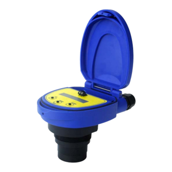
SAFETY PRECAUTIONS Step Three Make a Fail‐Safe System: Design a fail‐safe system that accommodates the possibility of switch and/or power failure. OMEGA ENGINEERING recommends the use of redundant backup systems and alarms in addition to the primary system. Flammable, Explosive or Hazardous Applications: LVU800 Series should not be used within classified hazardous environments. Warning: Always use the FKM gasket when installing the LVU800 Series, and make sure that all electrical wiring of the switch is in accordance with applicable codes. Components: LVU800 Series is offered in three different models. Depending on the model purchased, you ... -
Page 7: Getting Started
GETTING STARTED Step Four LVU800 Series can be configured before installation. The switch features non‐volatile memory, so the set points configured before installation will not be lost when the switch is powered down. To start, all you need is the following information: Basic Tank Information: o HEIGHT – Distance from the transducer face to the bottom of the tank. o FILL‐H – Maximum fill height of the liquid from the bottom of the tank. o These values will all be in the same distance value (inches, centimeters, feet or meters) and will all be measured from the bottom of the tank. Power: o Provide 12 to 28 VDC input power to the LVU800 Series. Feature Guide: FEATURE ACCESS BY Easy to use MENU ... -
Page 8: Getting Around
HOLD – Keeps the output at its last current reading when fail‐safe condition occurs. TG CAL – Target Calibration (allows for the sensor to accept the current level as either EMPTY or FULL. VALUES – Provides setup information, the ability to reset the LVU800 Series and a simulation mode to test the relay function. o SETUP – Will display the setting for all functions of LVU800 Series. o DIAG – This is a production test feature used by the factory to confirm operation. This mode should only be used when supervised by an Omega Engineering representative. o RESET – Will reset the LVU800 Series back to its original factory setting. HELP – Provides information for contacting Omega Engineering no‐line. RUN – Returns the unit to normal measurement and control mode. 8 ... -
Page 9: How To Enter The Menu
1. In the MENU mode, press select when UNITS is display. 2. Press SELECT to choose between INCHES, CM (centimeter), FEET, METERS or PERCENT. 3. Select EXIT to return to the Top Level Menu. Note: Reading the level of liquid in Percent: Omega Engineering recommends that when selecting PERCENT, configure the HEIGHT and FILL‐H settings before selecting PERCENT in order to span the LVU800 Series for your application requirements. When in PERCENT, the operational span will be based upon the last TANK settings, typically the factory settings for HEIGHT and FILL‐H. ... - Page 10 GETTING STARTED (continued) Step Four DISPLAY ‐ AIR Mode vs. LIQUID Mode: The display can be made to display either the height of liquid in the tank (LIQUID mode) or the amount of air in the tank (AIR mode). AIR mode – Will display the distance from the bottom of the sensor to the surface of the liquid. LIQUID mode – Will display the height of liquid measured from the bottom of the tank. How to change the display mode: 1. In the MENU mode, press select when UNITS is display. 2. Press SELECT when DISPLAY appears. 3.
-
Page 11: How To Configure The Operational Range (Height & Fill-H)
4. To enter the value, press and hold SELECT (Approximately 2 seconds) until SAVED is displayed. 5. When FILL‐H appears, press SELECT. 6. Using the UP and DOWN buttons, set the Fill Height (FILL‐H) to the maximum fill height of the liquid from the bottom of the tank. 7. Press and hold SELECT (2 seconds) to enter the value. 8. When EXIT appears, press SELECT return to Top Level Menu. Sensor Height Fill‐Height Note: Omega Engineering recommends that when selecting PERCENT, configure the Height and Fill‐H settings before selecting PERCENT in order to span the LVU800 Series for your application requirements. When PERCENT is selected, the TANK settings (Height and Fill‐H) will be disabled. 11 ... - Page 12 GETTING STARTED (continued) Step Four How to set a Reverse the Current Output: The default for LVU800 Series is to have 4 mA at Empty and 20 mA at Full. This is the normal (NORM) setting. The output can be reversed (REV) with 20 mA at Empty and 4 mA at Full. 1. In MENU mode, select the TANK item. 2. When REV MA appears, press SELECT. 3. When REV appears, press SELECT. 4. When EXIT appears, press SELECT return to Top Level Menu. LVU800 Series is now in the Reverse mode. To switch back to the Normal mode, follow the instructions above and select NORM under step 3. How to set the SAFE setting: The default for Fail‐Safety (LOST) can be preset. The choices are 4 mA, 20 mA, 21 mA, 22 mA and HOLD. ...
- Page 13 GETTING STARTED (continued) Step Four How to set using Target Calibration (Empty): Instead of measuring for Empty tank, the Empty distance can be set automatically. This method requires that the tank be Empty or at the level that is considered Empty in the application. To set TG Empty, follow the instructions below. 1. Before beginning, make sure the level is tank is at the Empty level. ...
-
Page 14: Wiring
WIRING Step Five Below is a quick review of wiring the LVU800 Series to common display, controllers and PLC’s. Proportional Level Controller Proportional Level Controller LVCN‐51 Series LVCN‐51 Series JWA mode (Factory Setting) JWB mode Generic Loop Generic PLC Powered Display 14 ... - Page 15 WIRING (continued) Step Five General notes for electrical connections, usage and safety: Where personal safety or significant property damage can occur due to a spill, the installation must have a redundant backup safety system installed. Wiring should always be completed by a licensed electrician. Supply voltage should never exceed 28 VDC. The sensor materials must be chemically compatible with the liquids to be measured. Design a fail‐safe system for possible sensor and/or power failure. Never use the sensor in environments classified as Hazardous. Testing the Transmitter 1. Connect a multimeter in series with the black wire to read the current output. 2. Verify that the current increases (tank filling) and decreases (tank emptying) appropriately in the calibrated span. 3. If not, carefully observe and attempt to correlate any installation, level or application event for more specific troubleshooting direction. ...
-
Page 16: Installation
Installation in existing fittings If the existing fitting is larger than the threads of the LVU800 Series, select a reducer bushing such as a 2” thread x 1” thread, a 2” slip x 1” thread, 3” thread x 2” thread or 3” slip x 2” thread. Metal Tanks (LVU809 series only) Omega Engineering ultrasonic transmitters have been optimized for use in non‐metallic fittings. 1. For best performance, avoid the use of metallic fittings. a. Use a plastic 2” x 1” reducer bushing (such as LVU800‐2N80), or a plastic 1” tank adapter (such as LVU800‐1B). 2. While installations directly into a 1” metal fitting are not recommended, acceptable results may be ... -
Page 17: Fitting Selection
INSTALLATION (continued) Step Six Fitting Selection: Check the part number to determine the required fitting mount size and thread type. LVU800 Series is commonly installed in tank adapters, flanges, brackets or standpipes. Note: Always include the gasket when installing the LVU800 Series. 1. Tank Adapter: Select a tank adapter fitting, such as a 1” adapter for the LVU809 series or a 2” adapter for the LVU816, LVU826 & LVU832 series. a. For best results, select a 2” tank adapter and add a 2” x 1” reducer bushing. b. Avoid tank adapter (thread x thread) styles and/or pipe stops forward of the installed transducer. ... - Page 18 INSTALLATION (continued) Step Six 3. Flange (LVU809 series): If installing on a flange, select a flange with a thread that is above the plane of the flange. a. The LVU816, LVU826 & LVU832 series works well with Flange installations. b. Avoid the use of blind flanges with tapped threads or flanges where the threads are even with the plane of the flange, such as the Banjo 1" Poly ANSI Flange (series AF100). c. Use a flange with a 2” thread and add a 2” to 1” reducer bushing to complete the installation. 2” Flange w/ 2” Flange w/ 2” Flange w/ thread out of plane thread in plane Reducer Bushing (LVU800‐2F shown) (LVU800‐2N80 shown) Do not use thread in plane 4. Side Mount Bracket: For installations in open tanks and sumps, use the LVM‐30 or LVM‐31 series side mount bracket. a.
- Page 19 INSTALLATION (continued) Step Six 5. Stand Pipe: A standpipe maybe used to dampen turbulence or when foam is present in the application. a. Pipe can be made of any material. b. Select a minimum 3” ID pipe for the stand pipe. i. A 2” pipe is usable with the LVU809 series, but is the minimum. ii. Pipes larger than 3” can also be used. c. Use a coupling and reducer bushing to attach the LVU800 Series to the pipe. i. With the LVU809 series, be sure to use a plastic reducing bushing such as the 2” Thread x 1” Thread fitting (ex: LVU800‐2N80) or 2” Slip x 1” Thread fitting (ex: LVU800‐2S80). ii. With the LVU816, LVU826 or LVU832 series, be sure to use a plastic reducing bushing such as the 3” Thread x 2” Thread fitting (ex: LVU800‐3N80) or 3” Slip x 2” Thread fitting ...
-
Page 20: Appendix
4. When completed, press SELECT when EXIT appears to return to the main program level. Diagnostics (DIAG) Parameters: This mode runs diagnostic tests that confirm operation of LVU800 Series. This mode should only be used when supervised by an Omega Engineering representative. Reset: LVU800 Series enables the end user to reset the entire configuration back to the original factory settings. ... -
Page 21: User Settings
APPENDIX Step Seven User Settings: Fill out the chart below and keep as a record of your configuration. Tank Height = Fill-H = Norm Reverse Units Inches Feet Meter Percent Liquid Safe 22mA 21 mA 20mA Hold Last 21 ... -
Page 22: Troubleshooting
APPENDIX Step Seven Troubleshooting: PROBLEM SOLUTION TANK does not appear on Units function is set for PERCENT on LVU800 Series: the main menu: When Units is set for PERCENT, the TANK function is disabled. To re‐enable TANK, change units to INCHES, CM, FEET or METERS. Display shows FULL: Level of liquid is above the FILL‐H setting: Check the FILL‐H ... - Page 23 23 ...
- Page 24 24 ...
Need help?
Do you have a question about the LVU800 Series and is the answer not in the manual?
Questions and answers