Table of Contents
Advertisement
Quick Links
Advertisement
Table of Contents

Related Manuals for Omega LVU2800 Series


Summary of Contents for Omega LVU2800 Series
- Page 1 LVU2800 Series Ultrasonic Level Transmitter...
- Page 2 2 of 23 ...
-
Page 3: Table Of Contents
INTRODUCTION / TABLE OF CONTENTS Step One The LVU2800 Series is a general‐purpose ultrasonic level transmitter that provides a loop powered 4‐20 mA output. The 4‐20 mA output can be used to provide the proportional level of liquid in any tank or vessel. The signal can be connected to any device that accepts a loop powered 4‐20 mA signal, such as a PLC, SCADA, DCS, display, controller, etc. New Features Simple configuration with push button configuration Adjustable Loop Fail‐Safe, Hold Last, Empty, Full, 21 mA, 22 mA Easy to reverse mA output, 4‐20 mA to 20‐4 mA Increased output filtering Table of Contents Introduction .............................. 3 Specifications .............................. 4 Dimensions .............................. 4 About this manual ............................. 5 Wiring .............................. 7 Getting Started .............................. 9 Feature Guide ............................ 9 Getting Around ........................... 10 How to enter the MENU ........................ 11 How to configure UNITS ........................ 11 ... -
Page 4: Specifications
SPECIFICATIONS/DIMENSIONS Step Two Range: LVU2810: 4" to 9.8' Loop resist.: 500 Ohms @ 24 VDC (10 cm to 3m) Signal output: 4‐20 mA, two‐wire LVU2818: 8" to 18.0' Signal invert: 4‐20 mA / 20‐4 mA (20 cm to 5.5m) Signal fail‐safe: 4mA, 20 mA, 21 mA, 22 mA, LVU2826: 8" to 26.4' hold last (20 cm to 8m) Process temp.: F: ‐4° to 140° LVU2832: 12" to 32.8' C: ‐20° to 60° (30 cm to 10m) Temp. comp.: Automatic Accuracy: ± 0.2% Ambient temp.: F: ‐31° to 140° of range ... -
Page 5: About This Manual
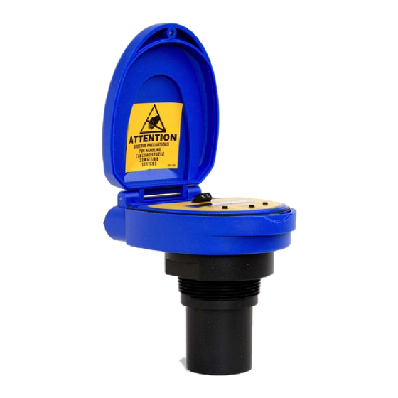
LVU2800 Series Ultrasonic Level Switch from OMEGA ENGINEERING. Please refer to the part number located on the switch label to verify the exact model configuration, which you have purchased. User’s Responsibility for Safety: OMEGA ENGINEERING manufactures a broad range of level sensing technologies. While each of these sensors is designed to operate in a wide variety of applications, it is the user’s responsibility to select a sensor model that is appropriate for the application, install it properly, perform ... - Page 6 SAFETY PRECAUTIONS Step Three Make a Fail‐Safe System: Design a fail‐safe system that accommodates the possibility of switch and/or power failure. OMEGA ENGINEERING recommends the use of redundant backup systems and alarms in addition to the primary system. Flammable, Explosive or Hazardous Applications: LVU2800 Series should not be used within classified hazardous environments. Warning: Always use the FKM gasket when installing the LVU2800 Series, and make sure that all electrical wiring of the switch is in accordance with applicable codes. Components: LVU2800 Series is offered in three different models. Depending on the model purchased, you may or may not have been shipped all the components shown below. You do however, need an LVU2800 Series and FKM gasket to configure, install and operate LVU2800 Series. LVU2800 Series o LVU2810 – 9.8’ (3 m) range, Type 4X encl., 1” NPT o LVU2818 – 18.0’ (5.5 m) range, Type 4X encl., 2” NPT o LVU2826 – 26.2’ (8 m) range, Type 4X encl., 2” NPT o LVU2832 – 32.8’ (10 m) range, Type 4X encl., 2” NPT FKM Gasket o Part #220128 – for LVU2810 series only o Part #220129 – for LVU2818, LVU2826 and LVU2832 series ...
-
Page 7: Wiring
WIRING Step Four Below is a quick review of wiring the LVU2800 Series to common display, controllers and PLC’s. Proportional Level Controller Proportional Level Controller LVCN‐51 Series LVCN‐51 Series JWA mode (Factory Setting) JWB mode Generic Loop Generic PLC Powered Display 7 of 23 ... - Page 8 WIRING (continued) Step Four General notes for electrical connections, usage and safety: Where personal safety or significant property damage can occur due to a spill, the installation must have a redundant backup safety system installed. Wiring should always be completed by a licensed electrician. Supply voltage should never exceed 28 VDC. The sensor materials must be chemically compatible with the liquids to be measured. Design a fail‐safe system for possible sensor and/or power failure. Never use the sensor in environments classified as Hazardous. Voltage Output LVU2800 Series can be used as a 0 to 5 or 0 to 10 VDC output device. A resistor will need to be added to the circuit to enable a voltage output (refer to the wiring diagram below). 0‐5 VDC output o Add a 250 Ohm resistor o Actual output will be 0.8 to 5 VDC 0‐10 VDC output o Add a 500 Ohm resistor o Actual output will be 2 to 10 VDC 8 of 23 ...
-
Page 9: Getting Started
GETTING STARTED Step Five LVU2800 Series can be configured before installation. The switch features non‐volatile memory, so the set points configured before installation will not be lost when the switch is powered down. To start, all you need is the following information: Basic Tank Information: o HEIGHT – Distance from the transducer face to the bottom of the tank. o FILL‐H – Maximum fill height of the liquid from the bottom of the tank. o These values will all be in the same distance value (inches, centimeters, feet or meters) and will all be measured from the bottom of the tank. Power: o Provide 12 to 28 VDC input power to the LVU2800 Series. Feature Guide: FEATURE ACCESS BY Easy to use MENU Press and hold SELECT key until MENU is displayed approximately 5 seconds. The MENU items will rotate through display, press SELECT to change an item. Many UNITS of In the MENU mode, press SELECT when UNITS is display, measurement. then select INCHES, CM (centimeter), FEET, METERS or PERCENT. No cumbersome measure In MENU mode, select the TANK item and set the required. Set point ... -
Page 10: Getting Around
REV MA – Allows the transmitter to reverse the current output such that 4 mA is at FULL and 20 mA is at EMPTY. o Press Exit to return to the Top level Menu. o Note: if UNITS is set to Percent, then TANK will not appear. To view TANK, set UNITS to any of the following: Inches, Centimeters, Feet or Meters. SAFE – The fail‐safe for the LVU2800 Series can be preset to the customer’s requirement. o 22 mA – Overfill fail‐safe setting. o 21 mA – Overfill fail‐safe setting. o 20 mA – Full fail‐safe setting. o 4 mA – Empty fail‐safe setting. o HOLD – Keeps the output at its last current reading when fail‐safe condition occurs. TG CAL – Target Calibration (allows for the sensor to accept the current level as either EMPTY or FULL. VALUES – Provides setup information, the ability to reset the LVU2800 Series and a simulation mode to test the relay function. o SETUP – Will display the setting for all functions of LVU2800 Series. o DIAG – This is a production test feature used by the factory to confirm operation. This mode should only be used when supervised by an Omega Engineering representative. o RESET – Will reset the LVU2800 Series back to its original factory setting. HELP – Provides information for contacting Omega Engineering no‐line. RUN – Returns the unit to normal measurement and control mode. 10 of 23 ... -
Page 11: How To Enter The Menu
GETTING STARTED (continued) Step Five How to enter the MENU: 1. Press and hold SELECT key (approximately 5 seconds) until MENU is displayed. 2. The menu items will rotate through display. 3. Press SELECT to change an item. How to configure UNITS: 1. In the MENU mode, press select when UNITS is display. 2. Press SELECT to choose between INCHES, CM (centimeter), FEET, METERS or PERCENT. 3. Select EXIT to return to the Top Level Menu. Note: Reading the level of liquid in Percent: Omega Engineering recommends that when selecting PERCENT, configure the HEIGHT and FILL‐H settings before selecting PERCENT in order to span the LVU2800 Series for your application requirements. When in PERCENT, the operational span will be based upon the last TANK settings, typically the factory settings for HEIGHT and FILL‐H. LVU2800 Series HEIGHT FILL‐H LVU2810 Series 118.1” (300 cm) 114.1” (290 cm) LVU2818 Series 216.5” (550 cm) 208.5” (530 cm) LVU2826 Series ... - Page 12 GETTING STARTED (continued) Step Five DISPLAY ‐ AIR Mode vs. LIQUID Mode: The display can be made to display either the height of liquid in the tank (LIQUID mode) or the amount of air in the tank (AIR mode). AIR mode – Will display the distance from the bottom of the sensor to the surface of the liquid. LIQUID mode – Will display the height of liquid measured from the bottom of the tank. How to change the display mode: 1. In the MENU mode, press select when UNITS is display. 2. Press SELECT when DISPLAY appears. 3. Press SELECT to choose between AIR or LIQUID. 4. When EXIT appears, press SELECT return to Top Level Menu. 12 of 23 ...
-
Page 13: How To Configure The Operational Range (Height & Fill-H)
1. In MENU mode, select the TANK item. 2. When HEIGHT appears, press SELECT. 3. Using the UP and DOWN buttons, set the HEIGHT of the tank from the transducer face to the bottom of the tank. 4. To enter the value, press and hold SELECT (Approximately 2 seconds) until SAVED is displayed. 5. When FILL‐H appears, press SELECT. 6. Using the UP and DOWN buttons, set the Fill Height (FILL‐H) to the maximum fill height of the liquid from the bottom of the tank. 7. Press and hold SELECT (2 seconds) to enter the value. 8. When EXIT appears, press SELECT return to Top Level Menu. Sensor Height Fill‐Height Note: Omega Engineering recommends that when selecting PERCENT, configure the Height and Fill‐H settings before selecting PERCENT in order to span the LVU2800 Series for your application requirements. When PERCENT is selected, the TANK settings (Height and Fill‐H) will be disabled. 13 of 23 ... - Page 14 GETTING STARTED (continued) Step Five How to set a Reverse the Current Output: The default for LVU2800 Series is to have 4 mA at Empty and 20 mA at Full. This is the normal (NORM) setting. The output can be reversed (REV) with 20 mA at Empty and 4 mA at Full. 1. In MENU mode, select the TANK item. 2. When REV MA appears, press SELECT. 3. When REV appears, press SELECT. 4. When EXIT appears, press SELECT return to Top Level Menu. LVU2800 Series is now in the Reverse mode. To switch back to the Normal mode, follow the instructions above and select NORM under step 3. How to set the SAFE setting: The default for Fail‐Safety (LOST) can be preset. The choices are 4 mA, 20 mA, 21 mA, 22 mA and HOLD. 1. In MENU mode, select the SAFE item. 2. When the required setting appears, press SELECT. 3. When EXIT appears, press SELECT return to Top Level Menu. 14 of 23 ...
- Page 15 GETTING STARTED (continued) Step Five How to set using Target Calibration (Empty): Instead of measuring for Empty tank, the Empty distance can be set automatically. This method requires that the tank be Empty or at the level that is considered Empty in the application. To set TG Empty, follow the instructions below. 1. Before beginning, make sure the level is tank is at the Empty level. 2. In MENU mode, select the TG CAL item. 3. When EMPTY appears, press SELECT. This sets the current distance as the new Empty setting. 4. When EXIT appears, press SELECT return to Top Level Menu. How to set using Target Calibration (Full): Instead of measuring for Full tank, the Full distance can be set automatically. This method requires that the tank be Full or at the level that is considered Full in the application. To set TG Full, follow the instructions below. 1. Before beginning, make sure the level is tank is at the Full level. 2. In MENU mode, select the TG CAL item. 3. When FULL appears, press SELECT. This sets the current distance as the new Full setting. 4. When EXIT appears, press SELECT return to Top Level Menu. ...
-
Page 16: Installation
For LVU2818, LVU2826 & LVU2832 Series ‐ mount at least 3” from the side wall 4. Do not mount where obstacles will intrude on sensor’s beam width a. See Specifications on page 3 5. Do not mount in a vacuum 6. Avoid mounting in the center of a dome top tank. 7. In cone bottom tank, position the sensor over the deepest part of the tank. Do not install at Do not install within angle relative to the 3” of tank sidewall. liquid. Do not install with Do not install in objects in the beam. applications with vacuum. Installation in existing fittings If the existing fitting is larger than the threads of the LVU2800 Series, select a reducer bushing such as a 2” thread x 1” thread, a 2” slip x 1” thread, 3” thread x 2” thread or 3” slip x 2” thread. Metal Tanks (LVU2810 series only) Omega Engineering ultrasonic transmitters have been optimized for use in non‐metallic fittings. 1. For best performance, avoid the use of metallic fittings. a. Use a plastic 2” x 1” reducer bushing, or a plastic 1” flange (See Fitting Selection on next page). 2. While installations directly into a 1” metal fitting are not recommended, acceptable results may be obtained if the 1” fitting is a half coupling in form and the outer diameter of the coupling is tightly wrapped in vinyl tape to dampen vibrations. 16 of 23 ... -
Page 17: Fitting Selection
INSTALLATION (continued) Step Six Fitting Selection: Check the part number to determine the required fitting mount size and thread type. LVU2800 Series is commonly installed in tank adapters, flanges, brackets or standpipes. Note: Always include the gasket when installing the LVU2800 Series. 1. Tank Adapter: Select a tank adapter fitting, such as a 1” adapter for the LVU2810 series or a 2” adapter for the LVU2818, LVU2826 & LVU2832 series. a. For best results, select a 2” tank adapter and add a 2” x 1” reducer bushing. b. Avoid tank adapter (thread x thread) styles and/or pipe stops forward of the installed transducer. c. Always mount the tank adapter so the majority of fitting is outside the tank. i. Never mount the tank adapter upside down or the bulk of the material is inside the tank. 2” Tank Adapter Tank Adapter Tank Adapter Socket x Thread w/ 2”x1” Reducer Bushing Thread x Thread Do not use thread x thread 2. Riser: Installations with tall, narrow risers can impede the acoustic signal. a. LVU2818, LVU2826 & LVU2832 Series: 2” (5 cm) diameter risers should be no taller than 5” (12.7 cm). Larger diameter risers should be no taller than 12” (30.5 cm). b. LVU2810 Series: Note: Do not exceed the dimensions listed above ... - Page 18 INSTALLATION (continued) Step Six 3. Flange (LVU2810 series): If installing on a flange, select a flange with a thread that is above the plane of the flange. a. The LVU2818, LVU2826 & LVU2832 series works well with Flange installations. b. Avoid the use of blind flanges with tapped threads or flanges where the threads are even with the plane of the flange, such as the Banjo 1" Poly ANSI Flange (series AF100). c. Use a flange with a 2” thread and add a 2” to 1” reducer bushing to complete the installation. 2” Flange w/ 2” Flange w/ 2” Flange w/ thread out of plane thread in plane Reducer Bushing Do not use thread in plane 4. Side Mount Bracket: For installations in open tanks and sumps, use the LVM‐30 series side mount bracket. a. For the LVU2810 series, order the LVM‐30 with a 2”x 1” Reducer Bushing. b. For the LVU2818, LVU2826 & LVU2832, series, order the LVM‐30 side mount bracket. 18 of 23 ...
- Page 19 INSTALLATION (continued) Step Six 5. Stand Pipe: A standpipe maybe used to dampen turbulence or when foam is present in the application. a. Pipe can be made of any material. b. Select a minimum 3” ID pipe for the stand pipe. i. A 2” pipe is usable with the LVU2810 series, but is the minimum. ii. Pipes larger than 3” can also be used. c. Use a coupling and reducer bushing to attach the LVU2800 Series to the pipe. i. With the LVU2810 series, be sure to use a plastic reducing bushing 2” Thread x 1” Thread fitting or 2” Slip x 1” Thread fitting. d. The pipe length should run the measurement span and the bottom of the pipe should remain submerged at all times to prevent foam from entering the pipe. e. Cut a 45°notch at the bottom of the pipe and drill a 1/4”pressure equalization hole in the dead band. f. The pumps should not drive liquid past the open end of the stand pipe which causes the liquid in the pipe to oscillate. 19 of 23 ...
-
Page 20: Appendix
APPENDIX Step Seven Setup: You can view how the LVU2800 Series is configured. 1. From the main MENU level, press SETUP when VALUES appears. 2. When SETUP appears, press the SELECT key. 3. Setup will display the following information: a. Units, Display, Rev mA, Safe, Height, Fill‐H 4. When completed, press SELECT when EXIT appears to return to the main program level. Diagnostics (DIAG) Parameters: This mode runs diagnostic tests that confirm operation of LVU2800 Series. This mode should only be used when supervised by an Omega Engineering representative. Reset: LVU2800 Series enables the end user to reset the entire configuration back to the original factory settings. Follow the instructions below to reset LVU2800 Series: 1. From the main MENU level, press SELECT when VALUES appears. 2. When RESET appears, press the SELECT key. 3. When YES appears, press SELECT key to reset LVU2800 Series. a. To cancel the reset, press SELECT when NO appears. 4. When completed, press SELECT when EXIT appears to return to the main program level. Factory Settings: LVU2800 Series HEIGHT FILL‐H LVU2810 Series 118.1” (300 cm) 114.1” (290 cm) LVU2818 Series 216.5” (550 cm) 208.5” (530 cm) ... -
Page 21: Troubleshooting
APPENDIX Step Seven Troubleshooting: PROBLEM SOLUTION TANK does not appear on Units function is set for PERCENT on LVU2800 Series: the main menu: When Units is set for PERCENT, the TANK function is disabled. To re‐enable TANK, change units to INCHES, CM, FEET or METERS. Display shows FULL: Level of liquid is above the FILL‐H setting: Check the FILL‐H ... - Page 22 22 of 23 ...
- Page 23 23 of 23 M‐5127/0312...
Need help?
Do you have a question about the LVU2800 Series and is the answer not in the manual?
Questions and answers