Table of Contents
Advertisement
Advertisement
Table of Contents

Related Manuals for Omega LVU500 Series


Summary of Contents for Omega LVU500 Series
- Page 1 ...
- Page 2 ...
-
Page 3: Table Of Contents
Understanding Sensor Height: ........................ 11 Understanding Fill-Height: ......................... 12-13 Sensor Output to Local Display: ......................14 Configuration: ..............................15 Configuring LVU500 Series with LVCN414-SW Software: ..............15 Step 1 – Install LVCN414-SW Software: ....................16 Software System Requirements: ....................16 ®... - Page 4 Introduction / Table of Contents Step One Wiring: ................................. 25 Wiring Diagram – Sample: ........................25 Wiring LVU500 series: ..........................25 Wire Connections: ........................... 26 General Notes for Electrical Connections, Usage and Safety: ............... 26 Common Wiring to Displays, Controllers & PLCs: .................. 27 Switching Inductive Loads: ........................
-
Page 5: Specifications
Introduction (continued) Step One SPECIFICATIONS Electrical: Environmental: Supply Voltage: 14-28 Vdc Process temperature: F: -40° to 176° Signal output: 4 to 20 mA current loop; 22 mA C: -40° to 80° max. Temp. compensation: Automatic Signal invert: 4-20mA or 20-4mA Ambient temp.: F: -31°... -
Page 6: Dimensions
Introduction (continued) Step One DIMENSIONS Dimensions for LVU501 & LVU503 Series Cable Dimensions for LVU501 & LVU503 Series... -
Page 7: About This Manual
Always check for leaks prior to system start-up. Wiring and Electrical: A supply voltage of 14 to 28 VDC is used to power the LVU500 series. Electrical wiring of the transmitter should be performed in accordance with all applicable national, state, and local codes. -
Page 8: Getting Started
Understand the location placement of the sensor relative to Measurement Range including Sensor Height and Fill-Height settings. b. Download the LVCN414-SW software from omega.com/ftp. 3. Configure Sensor with LVCN414-SW (Section Three) a. Section 3 contains information on using the LVCN414-SW configuration software. -
Page 9: Components
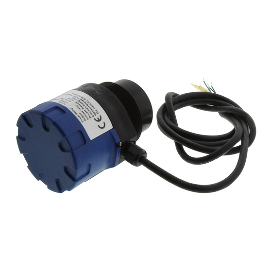
Section Two COMPONENTS The LVU500 series is offered in two different models with 4-20 mA output and relay control. Depending on the model purchased, you may or may not have been shipped all the components shown below. All G threaded process mounts require a FKM gasket for installation and operation of LVU500 series. -
Page 10: Basic Configuration
USB Fob. The LVU500 series can be configured before installation or after installation. The transmitter features non- volatile memory, so any settings configured before installation will not be lost when the sensor is powered down To start, the following information is required: ... -
Page 11: Understanding Sensor Height
UNDERSTANDING SENSOR HEIGHT This is a critical setting for LVU500 series. Sensor Height (SH) defines the location of the sensor from the bottom of the tank. The value must take into account the shape of the tank and any risers, fittings, structures or extensions associated with the tank or the installation (see examples below). -
Page 12: Understanding Fill-Height
Step Two UNDERSTANDING FILL-HEIGHT This is another critical setting for the LVU500 series. Fill-Height defines the location of the highest point in the tank where the sensor will read level changes. When the level rises above Fill-Height, the sensor will read full (as long as the level does not enter the dead band). - Page 13 Cone and Rounded Bottom Tanks The location of an LVU500 series installed along the top of a cone or rounded bottom tank may have an effect on the installation of the sensor. Be sure to understand the geometry directly underneath the sensor. Cone or rounded bottom tanks will provide off angled surfaces that can reflect the ultrasonic sound energy away from the sensor as the liquid level is lowered.
-
Page 14: Sensor Output To Local Display
SENSOR OUTPUT TO LOCAL DISPLAY/CONTROLLER LVU500 series outputs a 4-20 mA signal to a local display/controller or to remote devices such as PLCs, SCADA, DCS or other displays/controllers. The 4-20 mA signal is set relative to the Sensor Height and Fill- Height settings. -
Page 15: Configuration
Configuration Step Three LVU500 series can be configured before installation. The transmitter features non-volatile memory, so any setting configured before installation will not be lost when the switch is powered down. To configure, follow the steps below: 1. Install LVCN414-SW software a. -
Page 16: Step 1 - Install Lvcn414-Sw Software
LVCN414-SW (see omega.com/ftp) on your computer. Connect the red, green, white and black wires from LVU500 series into the correct terminals on the Fob. ® Tighten the screws on the terminals. Plug your Fob into the USB port of your computer. -
Page 17: Step 2 - Measure The Tank
Configuration (continued) Step Three STEP 2 - MEASURE THE TANK Measuring the tank is one of the most important aspects in configuring the sensor. When measuring the tank, take into account the location of the sensor with respect to fittings, risers, dome tops and bottoms, and identify where the measurements are taken from the sensor. -
Page 18: Step 3 - Sensor Configuration
(continued) Step Three With the LVU500 series connected to your computer, open the LVCN414-SW software by clicking on the LVCN414-SW icon. Follow steps 1-4 to configure the transmitter. Click “Help” in the lower right hand corner and open the help menu of LVCN414-SW for instructions on LVCN414-SW. If you need additional assistance using LVCN414-SW, please contact a Omega Engineering sales applications engineer at (833) 484-6072. -
Page 19: Step 4 - Dimensional Entry
Configuration (continued) Step Three STEP 4 – DIMENSIONAL ENTRY: Distance Mode (default): Output of sensor is based on the distance (height of liquid) in the tank. Any change in liquid level will reflect linearly to the current output. Note: Most applications will fall into this category. -
Page 20: Step 5 - Tank Level Confirmation
Configuration (continued) Step Three STEP 5 – TANK LEVEL CONFIRMATION: Verify the Height Units, Sensor Height, Fill-Height, Relay Units & Relay Settings. All values were calculated and set in the previous Dimensional Entry window. Make any adjustments if required. ... -
Page 21: Installation
Installation Step Four LVU500 series should always be mounted perpendicular to the liquid surface (use the provided FKM mounting gasket for G threaded versions only). Make sure that the fitting and transmitter threads are not damaged or worn. Always hand-tighten the transmitter within the fitting. Perform an installed leak test under normal process conditions prior to system start up. -
Page 22: Fitting Selection
Step Four FITTING SELECTION Check the part number to determine the required fitting mount size and thread type. The LVU500 series is commonly installed in tank adapters, flanges, brackets or standpipes. Note: Only use the gasket when installing an LVU500 series with a G thread (straight thread). - Page 23 Installation (continued) Step Four 3. Flange: If installing on a flange, select a flange with a minimum thread of 2” thread that is above the plane of the flange, such as the LVU800-2F. a. Use a flange with a 3” thread and add a 3” to 2” reducer bushing to complete the installation. 2”...
- Page 24 Vent Hole (1/4”) 3” Coupling (S x T) 3” PVC Pipe LVU500 series attached to a Avoid the use of a tee within the LVU800-3S40 (3” x 2” reducer stand pipe. A tee can create false bushing) to a Slip x Thread 3”...
-
Page 25: Wiring
Each configuration will have its own unique diagram. The diagram shown above is only a sample and should not be used as a wiring diagram. LVU500 series is a loop powered 4-20mA device. The power loop and current output loop are shared by the Red and Black wires. -
Page 26: Wire Connections
LVU500 series uses latching relays. When power is removed to the sensor, the relays will remain in their last state. Ex: If the relay is energized, when power is removed, the relay will remain in an energized state. -
Page 27: Common Wiring To Displays, Controllers & Plcs
Wiring (continued) Step Five COMMON LOOP POWERED 4-20MA WIRING TO DISPLAY, CONTROLLERS & PLC’S (CONTINUED) LVCN-51 Series LVCN-51 Series Level Controller Level Controller *JWA mode (Factory Setting) *JWB mode Generic Loop Generic PLC Powered Display * Refer to the LVCN-51 Series, Level Controller manual for information on JWA mode and JWB mode settings in the controller. -
Page 28: Switching Inductive Loads
Experiment for best results. VOLTAGE OUTPUT LVU500 series can be configured as a 0 to 5 VDC output. A resistor will need to be added to the circuit to enable a voltage output (refer to the wiring diagram below). ... -
Page 29: Lvcn414-Sw Software
SENSOR CONFIGURATION NUMBER OF PUMPS This feature allows you to select the number of pumps or valves used with the LVU500 series. This setting activates the control capabilities of one or two relays. Control relays are often referred to as latching relays. -
Page 30: Pump/Valve Action
LVCN414-SW Appendix (continued) Section Six PUMP/VALVE ACTION This feature allows you to select whether the pumps or valves will be used to automatically fill or empty the tank. For 2-Pump/Valve mode, both devices must be used in the same (automatic fill or empty) way. You cannot set one relay for fill and the other for empty. -
Page 31: Pump/Valve Mode
LVCN414-SW Appendix (continued) Section Six PUMP/VALVE MODE This feature allows you to select the control mode for a latching relay. Pump/Valve mode is not active for Switch/Alarms Only or 4-20 mA Transmitter Only. o Simplex – Allows the relay to be used for automatic fill or empty. -
Page 32: Relay Fail-Safe
LVCN414-SW Appendix (continued) Section Six RELAY FAIL-SAFE This feature allows you to select the fail-safe mode for the relays in the event that the sensor looses echo confidence. When the sensor regains echo confidence, the output current will revert back to the current level condition. -
Page 33: Switch/Alarm Configuration
LVCN414-SW Appendix (continued) Section Six SWITCH/ALARM CONFIGURATION This feature allows you to select the relay operation for the switch / alarm (used as a high or low alarm). The number of available relays is based upon the previous settings. o No Alarm – Turns OFF all remaining relays. o High Alarms –... -
Page 34: Switch Hysteresis/Dead Band
LVCN414-SW Appendix (continued) Section Six SWITCH HYSTERESIS/DEAD BAND This feature allows you to select a hysteresis or dead band for the remaining high and/or low alarms. o Options for Hysteresis/Dead band – No Hysteresis, ¼”, ½”, 1”, 2”, ½ cm, 1cm, 2 cm, 5 cm or Not Applicable. o High Alarms –... -
Page 35: Loop Fail-Safe
LVCN414-SW Appendix (continued) Section Six LOOP FAIL-SAFE This feature allows you to select the fail-safe current output if the sensor looses echo confidence. When the sensor regains echo confidence, the output current will revert back to the current level condition. o Hold Last Value –... -
Page 36: Volumetric Configuration
LVCN414-SW Appendix (continued) Section Six VOLUMETRIC CONFIGURATION The sensor may be configured in volumetric units (Gallons or Liters) or Distance (Height of Liquid) units (inches, cm, feet or meters). LVCN414-SW will default to Distance (Height of Liquid) with units of Inches. To change units or change from Distance to Volume, press the Volumetric Mode button as located near the center of the window. - Page 37 LVCN414-SW Appendix (continued) Section Six Shape Selection Window: This window will shows the different tank shape options available in LVCN414- Vertical Cylinder Vertical Cylinder with Cone Bottom Horizontal Cylinder with End caps Horizontal Cylinder with Spherical Ends ...
- Page 38 LVCN414-SW Appendix (continued) Section Six Volume – Sensor Output Units (Vertical Cylinder Example): Enter the dimensions of the tank. You must enter data in all fields shown. Sensor Height: Distance from the bottom of the tank to the top of the threads. Fill Height: Distance from the bottom of the tank to the operational full level of liquid (20mA).
-
Page 39: Tank Level Confirmation
LVCN414-SW Appendix (continued) Section Six TANK LEVEL CONFIRMATION This section of LVCN414-SW is where you confirm the values set in the previous step. The values were entered under the Dimensional entry window. To edit these settings, you must go back to the Dimensional entry window via the Volumetric Mode button. -
Page 40: Write To Unit
Stabilize Output in Dead Band: Placing a check mark in the box will activate a filter to hold the output at Full if the level enters the dead band of the LVU500 series. This filter requires the level to leave the dead band at a smooth and steady rate. -
Page 41: Appendix
Transmitter indicates a Immediately check the wiring for a short circuit. The LVU500 series is current current over 23 mA: limited to 22 mA. Anything above 23 mA indicates a short circuit. -
Page 42: Troubleshooting
(X is any number greater representative. than 2) -1 No device is attached to 1. Check the wires connected to the USB Fob as well as to the LVU500 series the USB Fob, or it is terminals. attached incorrectly. 2. Make sure the cable length between the sensor and the computer is less Please correct and try than 15’...
Need help?
Do you have a question about the LVU500 Series and is the answer not in the manual?
Questions and answers