
Subscribe to Our Youtube Channel
Related Manuals for Omega TX93


Summary of Contents for Omega TX93
- Page 1 User’ s Guide Shop online at TX93 omega.com Thermocouple Two-Wire e-mail: info@omega.com For latest product manuals: Temperature Transmitter omegamanual.info...
- Page 2 Servicing For immediate technical or North America: application assistance: U.S.A.: ISO 9001 Certified U.S.A. and Canada: OMEGA Engineering, Inc., One Omega Drive, Sales Service: 1-800-826-6342/1-800-TC-OMEGA ® P.O. Box 4047, Stamford, CT 06907-0047 USA Customer Service: 1-800-622-2378/1-800-622-BEST ® Toll-Free: 1-800-826-6342 TEL: (203) 359-1660 Engineering Service: 1-800-872-9436/1-800-USA-WHEN ®...
- Page 3 It is the policy of OMEGA Engineering, Inc. to comply with all worldwide safety and EMC/EMI regulations that apply. OMEGA is constantly pur-suing certification of its products to the European New Approach Directives. OMEGA will add the mark to every appropriate device upon certification.
- Page 4 Unpacking Instructions Remove the Packing List and verify that you have received all equipment, including: • TX93 Termocouple Two-Wire Temperature Transmitter • Operator’s Manual If you have any questions about the shipment, please call the Customer Service Department. When you receive the shipment, inspect the container and equipment for signs of damage.
-
Page 5: Table Of Contents
Mounting the TX93 ........ - Page 6 TX93 TABLE OF CONTENTS Thermocouple Two-Wire Temperature Transmitter Section Page Section 4 Troubleshooting Guide Section 5 Accessories Section 6 Specifications...
- Page 7 Introduction 1.1 General Description The OMEGA TX93 Thermocouple Two-Wire Temperature Transmitter ® accepts thermocouple sensor types J, K, T, or E and will produce a standard 4-20 mA output signal proportional to that produced by its attached input temperature sensor. Transmission of the proportional current output may be...
- Page 8 Introduction Figure 1-1 TX93 Transmitter Figure 1-2 Dimensions (in inches)
- Page 9 4 mA, at the low end of its temperature range, and increases to 20 mA, at the high end of its temperature range. (There are various temperature ranges thermocouple types available for the TX93. To order, refer to Section 1.3 for correct Model Numbers and Range Codes.)
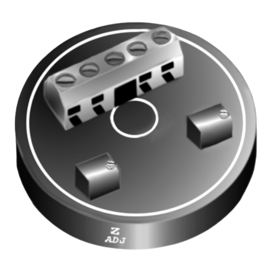
- Page 10 Introduction Figure 1-3 TX93 Thermocouple Transmitter...
- Page 11 The output current is used for recording, computing, or controlling. If the TX93 is mounted inside a protection head, (see Figure 3-1), the thermo- couple extension wires are replaced by two copper wires that carry the 4-20 mA...
- Page 12 Introduction The TX93 has reverse supply polarity protection and will operate with a wide range of supply voltages (7 to 35 Vdc). It has an input sensor break-protection circuit that forces the output current to go upscale when the thermocouple wire opens.
- Page 13 Introduction This leads to maximum error at approximately the midpoint of the range as shown in Figure 1-4. Figure 1-4 Straight Line Approximation of a Curve...
- Page 14 Introduction 1.2 Features • 4-20 mA output • 0.1% full-scale accuracy (with respect to the mV input signal) • Upscale break protection • Low Cost...
- Page 15 Introduction 1.3 Models Available Table 1-1. Range Code INPUT TYPES RANGE -40 to 120˚F – – 0 to 200˚F 0 to 300˚F 0 to 500˚F 0 to 750˚F 0 to 1000˚F –...
- Page 16 Introduction TX93 Models Available Model Number Description TX93-(*) Thermocouple Transmitter (J, K, T, or E) NB1TX93-(*) NB1 thermocouple probe, 12" L, ” O.D., ungrounded junction, 304SS sheath *Insert range code from Table 1-1 For complete information on NB1 Thermocouple probes, see the OMEGA Temperature Measurement Handbook ®...
-
Page 17: Section 2 Installation
1. surface mounted, 2. mounted inside a protection head (refer to Figure 2-1), or 3. installed into the OMEGA mounting track (part number RT) using an OMEGA mounting bracket (part number TX90-BR). 4. installed into standard 35mm DIN rail using an OMEGA DIN rail mounting adapter (part number TX-90-DIN). - Page 18 Installation Figure 2-4 shows a typical installation using the bracket and mounting track. Figure 2-5 shows the TX90-DIN adapter. Figure 2-1 Assembly of the Transmitter inside an OMEGA NB1 Protection Head (Dimensions in inches)
- Page 19 Installation CAUTION Hand tighten transmitter mounting screws only. Do not overtighten. Figure 2-2 RT Mounting Track (Dimensions in inches)
- Page 20 Installation Figure 2-3 TX90-BR Mounting Bracket (Dimensions in inches)
- Page 21 Installation Figure 2-4 Installation with the Bracket and Track (Dimensions in inches)
- Page 22 Installation Figure 2-5 TX 90-DIN DIN Rail Mounting Adapter (in Inches)
-
Page 23: Wiring The Tx93
Installation 2.2 Wiring the TX93 (Refer to Figure 2-6) 1. Connect a dc power supply in series with the load to the (+PS) and (-PS) power terminals. Note that the load (usually a monitoring instrument) may be connected to either the (+) or (-) power lead. - Page 24 Installation Figure 2-6 Wiring Diagram for the TX 93...
-
Page 25: Section 3 Calibration Instructions
• Precision DVM with ±0.002 mV accuracy and an adjustable mV source with 0.001 mV resolution • OMEGA TRC III Ice Point Reference (or stable ice bath) • Temperature Reference Probe (OMEGA P/N: TRP-(*) *Thermocouple Type J, K, T, E... -
Page 26: Set-Up Of Equipment
Insert the reference thermocouple. Figure 3-2 shows an alternate set-up. Here, a high precision thermocouple calibrator, such as the OMEGA Model CL511, replaces the DVM, ice bath, voltage source, etc. -
Page 27: Calibration Procedures
2. Select, from Table 3-1, the correct mV input values for the Z (zero) and S (span) adjustments that correspond to the model number. For example, for Model TX93-J2, the Z input is -0.886 mV, and the S input is 4.907 mV. - Page 28 Calibration Instructions If a Thermocouple Calibrator/Simulator is used, such as the OMEGA Model CL511 Precision Calibrator, select the Temperature Input Z (zero) and S (span) values. 3. Set the dc mV source to the selected Z (zero) mV value. Adjust the Z potentiometer to read 4.000 mA on the monitoring instrument.
- Page 29 Calibration Instructions Figure 3-1 TX93 Calibration Set-Up...
- Page 30 Calibration Instructions Figure 3-2 TX93 Calibration Set-Up (Alternate)
- Page 31 Calibration Instructions Table 3-1. Calibration Values for the TX93 Temperature mV Input mV Input Input Range Model Ref 32˚F Model Ref 32˚F Zero/Span TX93 Zero/Span TX93 Zero/Span -40/120˚F -1.961/2.527 – – 0/1200˚F -0.886/4.907 -0.692/3.820 0/1300˚F -0.886/7.949 -0.692/6.094 0/1500˚F -0.886/14.110 -0.692/10.561 0/1750˚F...
- Page 32 Calibration Instructions Table 3-1. Calibration Values for the TX93 (Continued) Temperature mV Input mV Input Input Range Model Ref 32˚F Model Ref 32˚F Zero/Span TX93 Zero/Span TX93 Zero/Span -40/120˚F – – -2.255/2.977 0/1200˚F -0.675/3.968 -1.026/5.871 0/1300˚F -0.675/6.648 -1.026/9.710 0/1500˚F -0.675/12.574 -1.026/17.945...
- Page 33 Troubleshooting Guide Malfunction or incorrect operation may be caused by: 1. Reversed polarity: Check the wiring using Figure 2-6 as a guide. If the temperature of the thermocouple increases while the current magnitude decreases, the problem could be caused by reversed polarity of the: a) thermocouple wiring b) power supply leads c) monitor instrument...
- Page 34 Troubleshooting Guide 2. Loose or broken wires: Check each terminal connection for tightness. Move each wire back and forth and note any changes in operation. 3. Too high a load resistance in the output current loop or too low a current rating on the power supply: Measure the total resistance of each device (excluding the transmitter and power supply) in the 20 mA loop, including the resistance of the lead wires.
- Page 35 17V/0.020A = 850 ohms. c) Make sure the power supply is rated for at least 28 mA times the number of TX93 transmitters being powered. For example, if the supply is powering five transmitters, the supply should be rated for at least 140 mA.
- Page 36 Accessories Model No. Description TX90-BR Mounting Bracket PSU-24B Unregulated Power Supply, 24 Volts TX82B Process Loop-Powered Indicator 48” Mounting Track TX90-DIN DIN Rail Mounting Adapter RAIL-35-2 6.5' Section 35mm DIN Rail...
- Page 37 Specifications General Size: 1.75” dia. X 0.75” high (includes terminal strip) Zero/Span Adjustment Range: ±25% Power Supply Voltage Operating Range: +7 Vdc to +35 Vdc, 28 mA max required per transmitter Accuracy: ±0.1% of full scale (includes effects of hysteresis, repeatability and linearity proportional to the T/C) Frequency Response: 3dB@ 3Hz...
- Page 38 Specifications Ambient Temperature: -13˚F to 185˚F (-25˚C to 85˚C) Storage Temperature Range: -85˚F to 257˚F (-65˚C to 125˚C) Thermal Zero Shift: <0.01%/˚F of span (span >10 mV) <0.02%/˚F of span (4-10 mV span) Thermal Span Shift: <0.01%/˚F of span Weight: 1.0 oz (28g) Output Current Output Span: 4-20 mA dc...
- Page 39 Specifications Maximum Loop Resistance: – 7V)/0.020A = ohms supply Load Resistance Effect: 0.01% of span per 300 ohms change Power Supply Effect: 0.002% of output span per volt Input Sensor: Thermocouple Input Break Protection: Upscale Impedance: >30 MΩ Source Current: 4 mA typical...
- Page 40 Notes...
- Page 41 Notes...
- Page 42 Notes...
- Page 43 In no event shall OMEGA be liable for consequential, incidental or special damages. CONDITIONS: Equipment sold by OMEGA is not intended to be used, nor shall it be used: (1) as a “Basic Component” under 10 CFR 21 (NRC), used in or with any nuclear installation or activity;...
- Page 44 Where Do I Find Everything I Need for Process Measurement and Control? OMEGA…Of Course! Shop online at omega.com TEMPERATURE DATA ACQUISITION Thermocouple, RTD & Thermistor Probes, Data Acquisition & Engineering Software Connectors, Panels & Assemblies Communications-Based Acquisition Systems Wire: Thermocouple, RTD & Thermistor Plug-in Cards for Apple, IBM &...
Need help?
Do you have a question about the TX93 and is the answer not in the manual?
Questions and answers