
Related Manuals for Omega TX90A Series


Summary of Contents for Omega TX90A Series
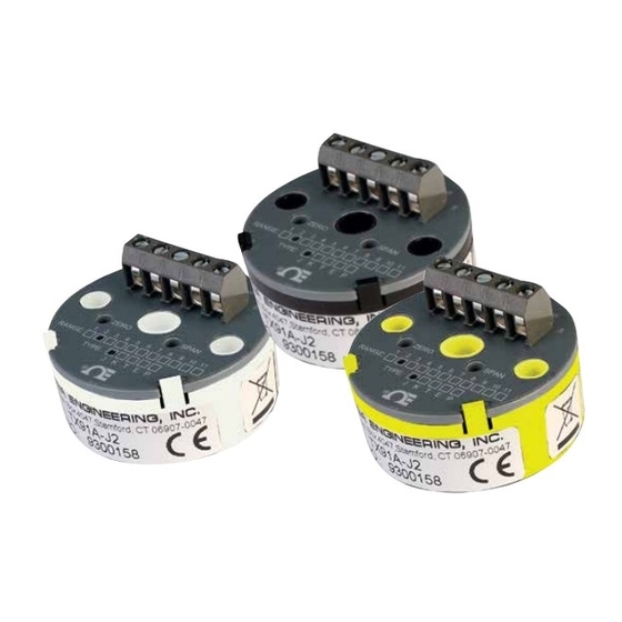
- Page 1 User’s Gui d e Shop online at omega.com e-mail: info@omega.com For latest product manuals: www.omegamanual.info TX91A (J, K, T, E) 4-20 mA Mini Temperature Transmitter...
- Page 2 Fax: (203) 359-7700 e-mail: info@omega.com For Other Locations Visit omega.com/worldwide The information contained in this document is believed to be correct, but OMEGA accepts no liability for any errors it contains, and reserves the right to alter specifications without notice.
-
Page 3: Table Of Contents
T T A A B B L L E E O O F F C C O O N N T T E E N N T T S S P P A A G G E E GETTING STARTED ......1 Unpacking . -
Page 5: Getting Started
SECTION 1 GETTING STARTED Unpacking Remove the packing list and verify that you have received all equipment. If you have any questions, contact the nearest Customer Service Department, as listed on the cover of this manual. Upon receipt of shipment, inspect the container and equipment for any signs of damage. -
Page 6: Available Ranges
Available Ranges As specified in Table 1-1, the transmitter has 10 ranges. Depending upon the range, the transmitter can measure temperature span as narrow as 160°F or as wide as 1000°F. A multi-turn, top-accessible potentiometer provides fine span tuning. A second top-accessible, multi-turn potentiometer provides a zero adjustment which allows placement of the 4-mA output temperature within +/- 25% for Fahrenheit and +/- 10% for Celsius of nominal span (refer to Section 3.0, Calibrating the Transmitter,... -
Page 7: Ordering Guide
1.5 Ordering Guide The model number describes the functionality of the transmitter. M M o o d d e e l l T T e e m m p p e e r r a a t t u u r r e e R R a a n n g g e e TX91A- -0 to 200°F -0 to 300°F... -
Page 8: Shock Resistance
1.6 Shock Resistance Lightweight TX91A transmitter circuit boards are fabricated from rigid, shock resistant materials with the components soldered to the circuit board. The TX91A transmitter's small size permits mounting into thermowells or wall mount- ing in confined areas. SECTION 2 CONNECTING POWER AND SIGNAL INPUTS •... - Page 9 SECTION 2 CONNECTING POWER AND SIGNAL INPUTS (continued) Table 2-1. Screw-Terminal Pin Assignment + Thermocouple - Thermocouple Earth Ground +Power/Signal Output -Power/Signal Output * For improved EMC performance, connect Pin 3 to Earth Ground. 1 2 3 4 5 02 03 04 05 06 07 08 09 10 RANGE: TYPE: J K T E P...
-
Page 10: Calibrating The Transmitter
CALIBRATING THE TRANSMITTER Calibration Setup: To prepare the ice bath: Fill a glass beaker with crushed ice made from distilled water. Fill the beaker with enough distilled water so that the ice bath just becomes slush, but not enough to float the ice. Insert the reference thermocouple. - Page 11 CALIBRATING THE TRANSMITTER (Continued) To calibrate the transmitter, follow these steps (refer to Figure 3-1): Locate the model number in Table 3-1 or 3-2 and set the millivolt source to the LO-IN value. Adjust the Zero potentiometer until the milliammeter reads 4.00 mA. Set the millivolt source to the HI-IN value (in your appropriate table) and read the output current on the milliammeter.
- Page 12 CALIBRATING THE TRANSMITTER (Continued) Table 3-1. Fahrenheit Temperature to Millivolt Conversion Chart V V a a l l u u e e M M o o d d e e l l N N u u m m b b e e r r / / R R a a n n g g e e T T X X 9 9 1 1 A A - - J J 2 2 J J 3 3...
- Page 13 CALIBRATING THE TRANSMITTER (Continued) Table 3-2. Celsius Temperature to Millivolt Conversion Chart V V a a l l u u e e M M o o d d e e l l N N u u m m b b e e r r / / R R a a n n g g e e T T X X 9 9 1 1 A A - - J J 7 7 J J 8 8...
-
Page 14: Specifications
4.0 SPECIFICATIONS I I N N P P U U T T Configuration: Non-isolated thermocouple input Thermocouple types: J, K, T, or E Thermocouple current: 1 uA max Burnout indication: Upscale over-range indication, 40 mA max. Thermocouple lead resistance: to 500 ohms for specified performance O O U U T T P P U U T T Linear range: 4 to 20 mAdc... - Page 15 4.0 SPECIFICATIONS (Continued) 2 3 4 5 1.750 [44.45] DIA. .650 .650 [1.650] [1.650] 1 2 3 4 5 1.150 [29.21] .750 [19.05] Figure 4-1. Case Dimensions > 4 REGULATOR < < –V CURRENT > 5 CONTROL Figure 4-2. Transmitter Block Diagram...
- Page 16 - NOTES -...
- Page 17 Department will issue an Authorized Return (AR) number immediately upon phone or written request. Upon examination by OMEGA, if the unit is found to be defective, it will be repaired or replaced at no charge. OMEGA’s WARRANTY does not apply to defects resulting from any action of the purchaser, including but not limited to mishandling, improper interfacing, operation outside of design limits, improper repair, or unauthorized modification.
- Page 18 Where Do I Find Everything I Need for Process Measurement and Control? OMEGA…Of Course! Shop online at omega.com TEMPERATURE M U Thermocouple, RTD & Thermistor Probes, Connectors, Panels & Assemblies M U Wire: Thermocouple, RTD & Thermistor M U Calibrators & Ice Point References M U Recorders, Controllers &...
Need help?
Do you have a question about the TX90A Series and is the answer not in the manual?
Questions and answers