
Related Manuals for Omega OS101


Summary of Contents for Omega OS101
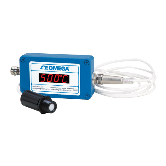
- Page 1 User’ s Guide MADE IN Shop online at omega.com OS101 e-mail: info@omega.com For latest product manuals: omegamanual.info OS102 OS100 SERIES Mini-Infrared Transmitter...
- Page 2 Toll Free in United Kingdom: 0800-488-488 e-mail: sales@omega.co.uk It is the policy of OMEGA Engineering, Inc. to comply with all worldwide safety and EMC/EMI regulations that apply. OMEGA is constantly pursuing certification of its products to the European New Approach Directives. OMEGA will add the CE mark to every appropriate device upon certification.
-
Page 3: Table Of Contents
Table of OS100 Series Infrared Transmitter Contents Table of Contents Section ..............Page Safety Warnings and IEC Symbols ......iii Caution and Safety Information ........iii Section 1 Introduction ..............1-1 Section 2 Installation ..............1-1 2.1 Unpacking and Inspection ........1-1 2.2 Electrical Connection .......... - Page 4 Table of OS100 Series Infrared Transmitter Figures Table of Figures Figure Description Page Power Supply & Analog Output Connections ..2-1 Alarm Output Connection ..........2-1 Main PC Board ............... 3-2 Sensor Housing .............. 3-2 Optical Field of View ............. 3-4 Setting the Temperature Engineering Unit....
-
Page 5: Safety Warnings And Iec Symbols
OS100 Series Safety Warnings and IEC Symbols This device is marked with international safety and hazard symbols in accordance with IEC 1010. It is important to read and follow all precautions and instructions in this manual before operating or commissioning this device as it contains important information relating to safety and EMC. - Page 6 OS100 Series NOTES:...
-
Page 7: Section 1 - Introduction
-18 to 538°C (0-1000°F) and provides a linear analog output of either 4-20 mA, 0-5 VDC, K type TC, 1 mV/°C, or 1 mV/°F. The new OS102 mini-infrared transmitter has all the functions of OS101 plus a built-in LED display that shows the measured temperature in degrees F or degrees C which is switchable in the field. -
Page 8: Electrical Connection
TX8-100 8 Conductor stranded Shielded cable (30 m, 100') PSU-93 Unregulated 16-24 VDC Power Supply CAL3-IR NIST Traceable Calibration Here are the Features of OS101 and OS102 infrared transmitters: Features OS101 OS102 Accuracy 2% Rdg or 4°F (2.2°C) Temp Range 0-1000°F (-18 to 538°C) -
Page 9: Power Supply & Analog Output Connections
OS100 Series - Operation 1mV/Deg 0-5VDC 4/20mA POWER SUPPLY ANALOG 12-24VDC OUTPUTS CHASSIS Figure 2-1. Power Supply & Analog Output Connections POWER 5-24VDC SUPPLY 12-24VDC CHASSIS Figure 2-2. Alarm Output Connection Section 3 - Operation Main Board The Main Board is shown in Fig. 3-1. Here are the important components on the board: (1) - Terminal Block for Power &... -
Page 10: Ambient Temperature
OS100 Series - Operation ALARM REAL TIME ALARM ADJUST E=0.95 Figure 3-1. Main PC Board 3.2 Ambient Temperature The Sensing head can operate in an ambient temperature of 0 to 70°C (32 to 158°F). The Sensing head in the high temperature model (-HT) can operate in an ambient temperature of 0 to 85°C (32 to 185°F) without any cooling required. -
Page 11: Atmospheric Quality
OS100 Series - Operation Atmospheric Quality Environments with smoke, dust, and fumes dirty up the optical lens, and cause erroneous temperature readings. To keep the surface of the optical lens clean, the air purge collar accessory is recommended, OS100-AP, See Fig. -
Page 12: Alarm Setting
The unit provides 0-100% alarm set point adjustment. Here is an example of an alarm setting. • An OS101-MA (4/20 mA output), the alarm is to be set at 400°F temperature. • Connect the alarm output as shown in Fig. 2-2. -
Page 13: Mounting Bracket Os100-Mb
OS100 Series - Operation 12.7 (0.5) (1/8) 12.7 (0.5) 50.0 (1.97) Ø 19 (0.755) (1/8) 25.4 Ø 4 (0.156) 23.3 Dimensions mm (in.) (.919) 31.8 (1.25) 42.9 (1.69) Figure 3-5. Mounting Bracket OS100-MB 1/8 NPT COMPRESSION FITTING , 2 PLCS. (.312) INLET OUTLET... -
Page 14: Air Purge Collar, Os100-Ap
4-40 THRD. HOLE, 2 PLCS. 109.5 (4.3125) DIN RAIL SNAP FEET Dimensions mm (in.) Figure 3-9. DIN Rail Mounting Adapter, OS-100-DR 65.5 DIM A (2.578) OS101 26.4 (1.04) 53.3 OS102 51.8 (2.04) (2.10) 5.7 (0.225) DIA. 47.7 (4) HOLES (1.880) (0.20) -
Page 15: Section 4 - Laser Sight Accessory
OS100 Series - Laser Sight Accessory Section 4 - Laser Sight Accessory Warning and Cautions CAUTION: You may receive harmful laser radiation exposure if you do not adhere to the warnings listed below: • Use of controls or adjustments or performance of procedures other than those specified here may result in hazardous radiation exposure. -
Page 16: Laser Sighting Accessory, Os100-Ls
OS100 Series - Laser Sight Accessory LASER WARNING LABEL SENSOR HEAD DC POWER JACK LED LASER LASER BEAM POWER (.75) INDICATOR 50.8 (2.0) ON/OFF SWITCH POWER CABLE Dimensions mm (in.) BATTERY PACK POWER SUPPLY Figure 4-1. Laser Sighting Accessory, OS100-LS ®... -
Page 17: Section 5 - Specifications
12 to 24 VDC @ 100 mA Analog Outputs MV-F 1 mV/°F MV-C 1 mV/°C K Type TC - OS101 only 4 to 20 mA 0 to 5 VDC Output Load requirements Min. Load (0 to 5VDC) 1 K-Ohms Max. Load (4 to 20 mA) -
Page 18: Laser Sight Accessory (Os100-Ls)
5.1 - General Con’t. Dimensions Sensor Head 25.4 OD. x 63.5 mm L (1" OD. x 2.5" L) Main Housing, OS101 65.5 W x 30.5 H x 115.3 mm L (2.58" W x 1.2" H x 4.54" L) Main Housing, OS102 65.5 W x 55.9 H x 115.3 mm L... - Page 19 OS100 Series - Emissivity Table Section 6 - Emissivity Table Material Emissivity (ε) Aluminum – pure highly polished plate ......0.04 to 0.06 Aluminum –...
- Page 20 OS100 Series - Emissivity Table Material Emissivity (ε) Asbestos Board ..........0.96 Asphalt, tar, pitch .
- Page 21 OS100 Series NOTES:...
- Page 22 OS100 Series NOTES:...
- Page 23 WARRANTY/DISCLAIMER OMEGA ENGINEERING, INC. warrants this unit to be free of defects in materials and workmanship for a period of 25 months from date of purchase. OMEGA’s WARRANTY adds an additional one (1) month grace period to the normal two (2) year product warranty to cover handling and shipping time. This ensures that OMEGA’s customers receive maximum coverage on each product.
- Page 24 Where Do I Find Everything I Need for Process Measurement and Control? OMEGA…Of Course! Shop online at omega.com TEMPERATURE Thermocouple, RTD & Thermistor Probes, Connectors, Panels & Assemblies Wire: Thermocouple, RTD & Thermistor Calibrators & Ice Point References Recorders, Controllers & Process Monitors Infrared Pyrometers PRESSURE, STRAIN AND FORCE Transducers &...
Need help?
Do you have a question about the OS101 and is the answer not in the manual?
Questions and answers