Table of Contents
Advertisement
Quick Links
OMNTEC
1993 Pond Rd., Ronkonkoma, NY 11779
Don't VOID Your Warranty!
Warranty will be void if OMNTEC®
EC-2 (Belden#8761) cable is not used
with MTG-series probe.
To initiate the warranty the warranty
card provided with this manual must be
completed and returned.
Phone 631-981-2001
®
Mfg., Inc.
Tank Gauging • Liquid Level and Leak Detection Systems • Relays
OEL8000II
Installation Manual
OMNTEC
O E L 8 0 0 O I I T A N K M O N I T O R I N G S Y S T E M
PRINT
OK
FAULT
ALARM
Version 5.33E
Fax 631-981-2007
MENU
TEST
ACK
DEL
1
2
3
DEF
ABC
GHI
4
5
6
JKL
MNO
PQR
7
8
9
STU
VWX
YZ_
0
- . ,
CURSOR LEFT
CURSOR RIGHT
August 2006
MTG PROBES MUST USE
BELDEN#8761 OR
OMNTEC® EC-2 CABLE.
LEAK SENSORS CAN
USE EQUIVELANT TO
OMNTEC® EC-4 OR
BELDEN#9940.
e-mail:
support@omntec.com
www.OMNTEC.com
Advertisement
Table of Contents
Troubleshooting

Related Manuals for Omntec OEL8000II


Summary of Contents for Omntec OEL8000II
- Page 1 CURSOR LEFT CURSOR RIGHT Version 5.33E August 2006 Don’t VOID Your Warranty! MTG PROBES MUST USE Warranty will be void if OMNTEC® BELDEN#8761 OR EC-2 (Belden#8761) cable is not used OMNTEC® EC-2 CABLE. with MTG-series probe. LEAK SENSORS CAN To initiate the warranty the warranty...
- Page 3 OEL8000II PROPRIETARY INFORMATION NOTICE ® This document contains information and material developed by OMNTEC Mfg., Inc. All rights are reserved. No part of this document may be reproduced, transmitted, processed or recorded by any means or form, electronic, mechanical, photographic or otherwise, without the express ®...
- Page 5 OEL8000II NOTICE Use of unauthorized parts in the OEL8000II system or modification to any parts of the ® system will nullify U.L. listing and our warranty. OMNTEC Mfg., Inc. will not be responsible for any liability claims arising from the performance of modified units.
- Page 7 OEL8000II OMNTEC LIMITED WARRANTY The seller, OMNTEC Mfg., Inc. warrants to buyer that product is free of defects when properly installed and maintained by user. Warranty period is one year from date of installation or 15 months from date of shipment from factory, whichever occurs first. The seller’s sole obligation is to repair or replace parts found to be defective upon evaluation...
-
Page 9: Table Of Contents
OEL8000II Table of Contents READ THIS FIRST!......................XIII SECTION 1 OVERVIEW .................... 1-1 1.1 S ....................1-1 YSTEM ESCRIPTION 1.2 S ........................1-1 AFETY 1.3 U ............1-2 NPACKING NSPECTION AND AMAGE LAIMS 1.4 R ........................1-3 ETURNS 1.5 E .................... - Page 10 Coefficient of Thermal Expansion................ 4-17 4.3.4.5 Tank Tilt ....................... 4-18 4.3.4.6 Product Height...................... 4-18 4.3.4.7 Water Height......................4-19 4.3.4.8 Thermistor Type ....................4-20 4.3.4.9 Probe Wire Speed ....................4-20 4.3.4.10 High Water Alarm Point ..................4-21 ® OMNTEC Mfg., Inc.
- Page 11 OEL8000II 4.3.4.11 Low/Low Product Alarm Point................4-21 4.3.4.12 Delivery Needed Alarm Point................4-22 4.3.4.13 Low Product Point ....................4-22 4.3.4.14 High Product Point ....................4-22 4.3.4.15 High Product Warning Point................. 4-23 4.3.4.16 Overfill Product Alarm Point................4-23 4.3.4.17 High/High Product Alarm Point ................4-23 4.3.4.18...
- Page 12 5.8 P CLD....................5-8 ROGRAMMING APPENDIX A PROBES....................A-1 APPENDIX B SENSORS....................B-1 APPENDIX C CONNECTOR SEALING KITS............C-1 APPENDIX D OEL8000II CONTROLLER ..............D-1 APPENDIX E REMOTE ANNUNCIATOR..............E-1 APPENDIX F INTERFACE BOARDS................F-1 APPENDIX G MODEM....................5-1 ® OMNTEC Mfg., Inc.
-
Page 13: Read This First
All work must be performed only by authorized personnel who are qualified using intrinsically safe design principles (NEC procedures) and are thoroughly familiar with the OEL8000II Installation Manual. At a minimum, it is the installer’s responsibility to be familiar with and to comply with intrinsic design principles as defined in the National Electrical Code. - Page 15 OEL8000II IMPORTANT SENSOR INFORMATION ONLY INSTALL BX-SERIES SENSORS WITH THE OEL8000II Please verify sensors have been installed according to the worksheet provided before calling technical support. Installation Manual...
- Page 17 OEL8000II Don’t VOID Your Warranty! Warranty will be void if OMNTEC EC-2 (Belden #8761) cable is not used with MTG-series probes. READ ME! Earth Ground Warning The earth ground terminal must be connected to maintain intrinsic safety as well as UL and NEC.
-
Page 19: Overview
Safety To install or service any component of the OEL8000II system the individual must be qualified using intrinsically safe design principles (NEC practices) and must be familiar with the specifications and procedures described within this manual. It is the responsibility of the installer and operator to be familiar with and to comply with all codes and regulations. -
Page 20: Unpacking, Inspection And Damage Claims
The buyer assumes all risk for damage or loss of merchandise incurred during shipping and is responsible for filing and settling any claims. If you report your loss ® to OMNTEC Mfg., Inc. however, we will attempt to assist you with your claim. ®... -
Page 21: Returns
OEL8000II Returns ® You must obtain a Return Material Authorization (RMA) from OMNTEC Mfg. before returning shipments. Shipments that are returned without such authorization will be rejected. It is also your responsibility to pre-pay all freight charges for returned material. Material for which an RMA has been provided may be shipped to: OMNTEC Mfg., Inc. -
Page 22: Conduits
♦ Probe and sensor cables must be run in conduits that are separate from other wiring. ♦ All wiring must enter the controller through the designated preformed knockouts (see Appendix D – OEL8000II Controller). Failure to comply can create an electric shock or explosion hazard causing death, personal injury, or WARNING property damage. - Page 23 OEL8000II ♦ Rigid metal conduit, 3/4 inch or larger (use reducer coupling, do not drill into box) is recommended between the controller and the tank area. ♦ Do not combine probe and sensor cables with other wires in the same conduit.
-
Page 25: Equipment
Equipment Controller The OEL8000II’s controller is mounted in a non-hazardous area and requires 100- 240 VAC, 50/60 Hz, 60 watts. It monitors all probes and sensors providing status and alarm information on its LCD display or thermal printer. The controller can be programmed to respond to an alarm condition by activating alarm relays that can automatically shut off power to one or more pumps and/or dispensers. -
Page 26: Bx-Series Sensor Worksheet
Note: When the liquid level at the probe riser is higher than liquid level at the fill riser, D is a negative value and must be entered as such. D = _________ (inches) 6. Calculate the tank tilt using the following equation: ® OMNTEC Mfg., Inc. -
Page 27: Controller Installation
♦ Allow for sufficient clearance around the controller for conduit access. All conduits will enter the controller through the designated preformed knockouts. (see Appendix D – OEL8000II Controller). ♦ Avoid installing in corners. ♦ Avoid swinging doors that can bang into the panel. -
Page 28: Mounting The Controller
All wiring must be performed in accordance with Control Drawing No. CDOEL8000II. Before making any connections inside the panel, refer to the following drawings in Appendix D – OEL8000II Controller: ♦ Control Drawing No. CDOEL8000II (required for installation) ♦ Intrinsically Safe Barrier Cover ♦... -
Page 29: Junction Boxes
OEL8000II Fig. 2-2: Panel Knockouts for Conduit Circuitry Note: K-3 through K-6 lead to intrinsically safe circuit location, (see Appendix D – OEL8000II Controller). 2.2.3 Junction Boxes Mount waterproof junction boxes in manways so as to provide access to probe and sensor connections after installation. -
Page 30: Ac Power Line
OEL8000II Controller). 2.2.6 Telephone Connections at the Controller The OEL8000II can be used with a line sharing device; consult factory for details. Do not use any extensions or services such as Call Waiting. These features can interrupt communications. Bring the telephone cable to the controller via conduit and connect to the RJ11 jack located on the left side of the controller (see Appendix D –... -
Page 31: Main Panel And Sub-Panel Grounding
Pull the wire through the rigid metal conduit and connect it directly to the ground bar of the main electrical service panel, not a sub-panel. Do not rely on the metal conduit as ground. See Appendix D – OEL8000II Controller for sub-panel wiring instructions. -
Page 32: Mtg Probe Length
(e.g., pumping gas while test is in progress). When wired in accordance with Control Drawing No. CDOEL8000II (see Appendix D – OEL8000II Controller), each OEL8000II controller can monitor up to eight magnetostrictive probes (KOEL8000II kits monitor up to four magnetostrictive probes). -
Page 33: Riser Pipe Minimum Length Requirements
OEL8000II 2.3.2.1 Riser Pipe Minimum Length Requirements 1. Add 2.5 inches to the probe length (see Section 2.3.1 – MTG Probe Length) for cable connector assembly. 2. Measure the diameter of the tank. 3. Subtract the tank diameter in Step 2 from the value calculated in Step 1. -
Page 34: Mtg Probe Installation
Probes. This probe monitors the tank’s water level, product level, and temperature. For petroleum applications and chemical applications, refer Appendix A – Probes. Consult OMNTEC for specific installation guidelines appropriate to the chemicals being stored. The MTG Probe has three wires that are color coded as follows:... -
Page 35: Probe Cable
Follow the instructions provided with the kit and refer to Appendix C – Connector Sealing Kits. Note: You must use Shielded cable #22 AWG (Belden #8761) or OMNTEC part # EC-2. For cable lengths greater than 1,000 feet contact OMNTEC Mfg., Inc. for further instructions. -
Page 36: Sensors
BX-series sensors). A microprocessor is built into each BX sensor that gives it the ability to communicate with the OEL8000II controller. Each controller is equipped with two buss connectors. Each is capable of accepting up to 22 sensors. -
Page 37: Sensor Cable
OEL8000II discriminate between water and hydrocarbons. An un-alarmed condition exists in a dry environment where light is reflected back to the photo-sensor. The presence of hydrocarbons will cause the optics sensor to initiate an alarm. The presence of water will cause the conductance sensor to initiate an alarm. -
Page 38: Riser Pipe For Bx-Pdwf
Note: The top of the riser should be no more than 18 inches below grade level. For example: If distance from the grade level to the top of the tank is 50 inches, you would perform the following calculations: ® 2-14 OMNTEC Mfg., Inc. -
Page 39: Bx-Pdwf Installation
3. Attach the riser cap (not supplied). 4. Install the 3/4 inch NPT oil tight cord grip provided with the sensor for strain relief. Be sure to seal properly to prevent the possibility of water intrusion. From OEL8000II To Network Strain Relief 4"... -
Page 40: Bx-Pdws
Note: The top of the riser should be no more than 18 inches below grade level. For example: If distance from the grade level to the top of the tank is 50 inches, you ® 2-16 OMNTEC Mfg., Inc. -
Page 41: Bx-Pdws Installation
5. Tighten the cable clamp to seal around cable and 2" by 3/4" bushing. Be sure to seal properly to prevent the possibility of water intrusion. Note: Ensure that the sensor is accessible and replaceable from grade level From OEL8000II To Network Strain Relief 2"... - Page 42 Install the 3/4-inch NPT oil tight cord grip provided with the sensor for strain relief. Be sure to seal properly to prevent the possibility of water intrusion. Note: Ensure that the sensor is accessible and replaceable from grade level. From OEL8000II To Network Strain Relief...
-
Page 43: Bx-L12, Bx-L20, Bx-Lv Series
OEL8000II 2.4.5 BX-L12, BX-L20, BX-LV Series The BX-L12, BX-L20, BX-LV (see Figure 2-11 is an optical sensor with a 2-inch NPT bushing that is an integral part of the sensor. It is inserted into an appropriate 2-inch opening on the top of the tank (see Figure 2-12). It is used for high level detection of the product. -
Page 44: Bx-Lm* Series
(6) inches above the bottom of the tank. This is to allow for tank deflection. Note: Ensure that the sensor is accessible and replaceable from grade level. ® 2-20 OMNTEC Mfg., Inc. -
Page 45: Bx-Res
OEL8000II HIGH LEVEL CAUTION OR LOW LEVEL Fig. 2-13: BX-LM* 2.4.7 BX-RES The BX-RES (see in Figure 2-14) is an optical reservoir sensor used in the tank’s interstitial space containing a brine solution. A rise in the level of the reservoir liquid is indicative of outside water getting in due to a breach in high ground water conditions, or product due to an inner wall breach in high ground water conditions. -
Page 46: Riser Pipe For Bx-Res
3. Install the 3/4 inch NPT oil tight cord grip provided with the sensor for strain relief. Be sure to seal properly to prevent the possibility of water intrusion. Note: Ensure that the sensor is accessible and replaceable from grade level ® 2-22 OMNTEC Mfg., Inc. -
Page 47: Bx-Ls
OEL8000II From OEL8000II To Network Strain Relief 4" BX-RES Reservoir Sensor Fig. 2-15: BX-RES Optical Reservoir Sensor 2.4.8 BX-LS The BX-LS sensor (see Figure 2-16) is used for detecting leaks in manways, dikes, and sumps above or below ground. It uses optical technology to detect liquid presence. -
Page 48: Bx-Lsr
♦ 4 inch NPT ♦ made of ANSI schedule 40 pipe ♦ threaded on both sides Minimum Length Requirements For this application, the minimum length of the riser must be 18 inches so as to cover the handle. ® 2-24 OMNTEC Mfg., Inc. -
Page 49: Bx-Lwf Installation
The BX-TC-1 (see Figure 2-18) was designed to monitor temperatures ranging from - 50° to 150°C with an accuracy of ± 1°C. High and low temperature alarm points are user programmable. Temperature ranges for alarm conditions are set in the OEL8000II’s programming (see Section 4.3.10.1.4 – Temperature (BXTC) Sensor 2-25 Installation Manual... - Page 50 ♦ ERASE ALL – to erase present settings for this sensor ♦ SELECT – to scroll from one setting to another ♦ DEFAULT – to set settings to default settings (LO = 33, HI = 45, ON = 38, OFF = 41) ® 2-26 OMNTEC Mfg., Inc.
-
Page 51: Bx-Vs
OEL8000II Enter in the location number or press select to move the cursor to the next selection. Enter in a value for “LO” (low alarm setting), “HI” (high alarm setting), “ON” (relay trip temperature) and “OFF” (relay trip temperature). The “ON”... -
Page 52: Annunciators (Ras Series)
Equipment the connections at the controller. Must use Belden #9940 cable or equivalent, see Section 2.4.1 – Sensor Cable. From OEL8000II To next sensor controller or (up to 22 sensors per buss) previous sensor on buss twist all drains and seal... -
Page 53: Mounting The Annunciator
RAS-4 Fig. 2-20: Annunciators Note: There is a fifth type of Annunciator model available for the OEL8000II. The RAS-1-NYS is similar to the RAS-1 except it has a large strobe light (60,000 candle power) and a louder horn (110 dB multi-frequency). Wiring for this model is the same as the RAS-1. -
Page 54: Wiring Configuration For Annunciators
Horn Alarm BLACK = WHITE = LED for tank #1 BROWN = LED for tank #2 RAS-3 (three tanks)⎯seven wire = Power BLUE = Horn Silence (Acknowledge) Switch GREEN = Horn Alarm BLACK = GND ® 2-30 OMNTEC Mfg., Inc. -
Page 55: Annunciator Connections At The Controller
OEL8000II WHITE = LED for tank #1 BROWN = LED for tank #2 ORANGE = LED for tank #3 RAS-4 (four tanks)⎯eight wire = Power BLUE = Horn Silence (Acknowledge) Switch GREEN = Horn Alarm BLACK = GND WHITE = LED for tank #1... -
Page 56: Interface Boards (Ib-Series)
(see Section 4.3.10 – Int Brd and Appendix F – Interface Boards for installation). ♦ IB-RAS ♦ IB-C420 ♦ IB-12V ♦ IB-RB2 ♦ IB-NET ® 2-32 OMNTEC Mfg., Inc. -
Page 57: Remote Communications
RS232 outputs. This allows for real time monitoring of the system and downloading of status information to any remote location, (See Section 2.2.6 – Telephone Connections at the Controller). A user friendly software program (OMNTEC-PC) or serial communication sheets are ® available; call OMNTEC Mfg., Inc. -
Page 59: Applying Power
OEL8000II Section 3 Applying Power Preparations The final steps in this installation consists of applying AC power to the controller followed by programming the controller. Before you apply AC power, do the following: (1) review the Checklist below and (2) fill out the System Start-up List on the next page to confirm that all installation steps have been completed. -
Page 60: System Start-Up Checklist
OEL8000II sensor wiring runs not to exceed 2000ft from the controller to the furthest sensor MTG-probe wiring is 22 gauge OMNTEC EC-2 or Belden#8761 cable – use of equivalent will VOID warranty MTG shield drain wire is connected to the ground terminal at the MTG connector in the controller... -
Page 61: Connecting Power
How to print out inventory reports How to start and stop an in-tank leak detection test (if applicable) How to enable auto alarm printout Only qualified and authorized personnel can install or service any component of the OEL8000II system Start-up Installer Dealer/Manager/Owner... -
Page 63: Programming
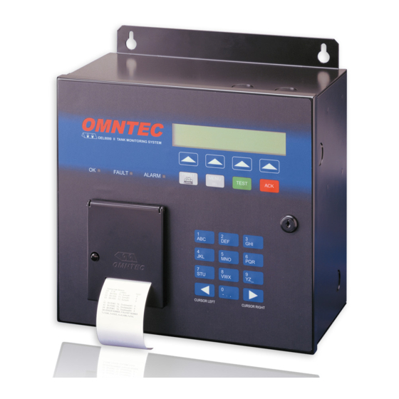
Mounting Holes Arrow Keys LEDs Function Keys Printer Cover Lock Feeder Button Data Keypad Paper Slot Mounting Holes Fig. 4-1: OEL8000II Controller’s Front Panel Installation Manual... -
Page 64: Procedure
Tactile Keypad This section describes the use of the tactile keypad during programming. Refer to the OEL8000II Owner’s Manual for additional information on the controller’s front panel displays and controls. ♦ Arrow Keys – Four upward pointing arrows point to the fields shown on the last line of the LCD display. -
Page 65: Printer
OEL8000II Note: The cursor will automatically advance when entering data. To use the same key consecutively, use the right cursor key to advance or wait for 2 seconds and the cursor will advance automatically. You can insert a blank by pressing the cursor key or by pressing the 9 key four times. - Page 66 Fig. 4-3c: Main Menu – Screen #3 TU 02/06/07 15:24:31 *STATUS:NORMAL DROP E/D |PRNT DROP |TEMP SNSR |MORE Fig. 4-3d: Main Menu – Screen #4 *TEMP SNSR only shows when a BX-TC is installed in unit. ® OMNTEC Mfg., Inc.
-
Page 67: Entering The Setup Mode
OEL8000II TU 02/06/07 15:24:31 *STATUS:NORMAL SHIFT LOG | |DIAG. |MORE Fig. 4-3e: Main Menu – Screen #5 TU 02/06/07 15:24:31 *STATUS:NORMAL |PRINTER |MORE Fig. 4-3f: Main Menu – Screen #6 4.3.1 Entering the SETUP Mode Starting in Screen #1 of the Main Menu, select SETUP. - Page 68 To exit the SETUP Menu, press the MENU key (below the arrow keys). The LCD will return to the MAIN Menu. TU 02/06/07 15:24:31 *STATUS:SETUP LOCATION |TANK |SENSOR |MORE Fig. 4-5a: Setup Menu – Screen #1 ® OMNTEC Mfg., Inc.
- Page 69 OEL8000II TU 02/06/07 15:24:31 *STATUS:SETUP ALARM LOG |DROP LOG |CITLD LOG |MORE Fig. 4-5b: Setup Menu – Screen #2 TU 02/06/07 15:24:31 *STATUS:SETUP VLD LOG |SHIFT |REMOTE |MORE Fig. 4-5c: Setup Menu – Screen #3 TU 02/06/07 15:24:31 *STATUS:SETUP COMM...
-
Page 70: Location Data
1. Enter the site name. System Response The site name appears on line 3. 2. Select ENTER. System Response Lines 1 and 4 of Figure 4-6 remain unchanged. Line 2 reads: Set security code, 6 Numeric Digits. ® OMNTEC Mfg., Inc. -
Page 71: New Security Code
OEL8000II Line 3 displays the default code 000000 or the current security code, if one has already been programmed into the system. 4.3.3.2 New Security Code A security code consists of number only. To enter new code, begin with Step 1. If you wish to keep the existing security code, skip to Step 3. -
Page 72: Site Address Line 1
Lines 1 and 4 of Figure 4-6 remain unchanged. Line 2 reads: Set the site city. Line 3 displays a cursor. 4.3.3.6 Site City 1. Enter the city (maximum of 20 characters). System Response The city will appear on line 3. ® 4-10 OMNTEC Mfg., Inc. -
Page 73: Site State
OEL8000II 2. Select ENTER. System Response Lines 1 and 4 of Figure 4-6 remain unchanged. Line 2 reads: Set the site state, (2 character). Line 3 displays a cursor. 4.3.3.7 Site State 1. Enter the state (maximum of 2 characters). -
Page 74: Site Manager's Name
This information is for factor use only. The site identification number is set by the manufacturer and cannot be changed in the field. 1. Enter the site identification number (maximum of 8 characters). This is the OEL8000II Controller Serial #. System Response The site identification number will appear on line 3. -
Page 75: Citld Enable Code
Line 3 displays a cursor. 4.3.3.13 CITLD Enable Code Contact the manufacturer for additional information on this feature. 1. Enter the CITLD Enable Code provided by OMNTEC. System Response The CITLD Enable Code will appear on line #3. 2. Press the arrow beneath ENTER. -
Page 76: Tank Data
When you have two or more similar tanks, you can use this procedure to copy data from a previously programmed tank. Note that not all of the copied data may apply to the new tank. After copying, review all data and make changes where applicable. ® 4-14 OMNTEC Mfg., Inc. - Page 77 OEL8000II Failure to comply with recommendations may result in improper operation of system. CAUTION 1. Enter the number of the tank to be programmed. System Response The tank number appears on line 3. 2. Select COPY. System Response The screen will appear as in Figure 4-7b.
-
Page 78: Tank Identification
This section permits you to enable or disable the level probe associated with the tank you identified in the previous section. Line 3 displays the currently programmed value. If you want to keep this value, skip to Step 3. 1. Press the DEL key to erase the old value. ® 4-16 OMNTEC Mfg., Inc. -
Page 79: Product Type
OEL8000II System Response Line 3 will become blank and show a blinking cursor. 2. Enter E for enable or D for disable. Note: If any character other than E is entered, the system will automatically program the default value – D. -
Page 80: Tank Tilt
(during this procedure product must be stagnant). Failure to comply with recommendations may result in improper operation of system. CAUTION If you do not wish to enter values at this time, you can skip these sections (enter 0 ® 4-18 OMNTEC Mfg., Inc. -
Page 81: Water Height
OEL8000II and select ENTER; repeat for Water Height). You may choose to return to this section after you have finished the rest of the programming. To enter values, do the following: 1. Obtain stick-readings of the product height and of water height (for water height, use a water paste on the stick). -
Page 82: Thermistor Type
This value has been factory programmed to 9.000 (default value). You may change the programming by finding the value on the probe label and entering it as follows: 1. Enter the probe wire speed. System Response The probe wire speed will appear on line 3. ® 4-20 OMNTEC Mfg., Inc. -
Page 83: High Water Alarm Point
OEL8000II 2. Select ENTER. System Response Lines 1 and 4 of Figure 4-7c remain unchanged. Line 2 reads: Set the high water alarm point, (In). Line 3 shows 3.0. 4.3.4.10 High Water Alarm Point This value has been factory programmed to 3.0” (default value). If the tank’s water level should rise to this level, the high water alarm will be activated. -
Page 84: Delivery Needed Alarm Point
The factory programmed value is 101% (default value). To change the value, do the following: 1. Enter the high product point in percent (enter 101 to disable feature). System Response The high product point will appear on line 3. ® 4-22 OMNTEC Mfg., Inc. -
Page 85: High Product Warning Point
OEL8000II 4.3.4.15 High Product Warning Point The value is a percentage of the tank capacity. If the tank’s product level rises to this level, the high product warning point will be activated. The factory programmed value is 85% (default value). -
Page 86: Probe Length
Volume Offset is a calibration to compensate for consistent discrepancies that may be found between actual and displayed volume. Important! When initially programming the controller, leave the default value of zero (0). 1. Enter the volume offset in gallons (maximum of 10 numerical characters). ® 4-24 OMNTEC Mfg., Inc. -
Page 87: Automated Vld (Volume Leak Detection Test)
OEL8000II System Response The volume offset will appear on line 3. 2. Select ENTER. System Response Lines 1 and 4 of Figure 4-7c remain unchanged. Line 2 reads: Enable/Disable/All Tanks, VLD test,E/D/A. Line 3 shows a cursor. 4.3.4.22 Automated VLD (Volume Leak Detection Test) This feature is used for setting a specific time interval for running the VLD test. - Page 88 ♦ If you select W in Step 3, enter a date and select ENTER. System Response Lines 1 and 4 of Figure 4-7c remain unchanged. Line 2 reads: Set daily test time, 00:00 – 23:59. Line 3 shows a cursor. ® 4-26 OMNTEC Mfg., Inc.
-
Page 89: Sudden Loss Limit
OEL8000II This screen is relevant to all test intervals. Enter the time of the day the test should be conducted. For example, enter 00.00 for midnight. 7. Enter the time of day. System Response The time of day will appear on line 3. -
Page 90: Sensor Data
(see Section 4.3.5.1.4 – Temperature Sensor Programming and Section 4.3.5.1.5 – Vapor Sensor Programming). Contact the manufacturer if your system includes a humidity sensor. Starting in Screen #1 of the SETUP Submenu (see Figure 4-5a), select SENSOR. ® 4-28 OMNTEC Mfg., Inc. - Page 91 OEL8000II Note: To return to the MAIN Menu from the Sensor Submenu, select EXIT and then press the MENU key. The LCD returns to Screen #1 of the MAIN Menu (see Figure 4-3a). System Response The screen will appear as in Figure 4-8a.
-
Page 92: Config (Sensor) Submenu
Figure 4-9d. Note: When selecting CONFIG during subsequent programming, Figure 4-9c will be displayed only if new sensors are found. TU 02/06/07 15:24:31 *STATUS:SETUP Please Wait… CONFIG |TEST/DEL |EXIT Fig. 4-9a: Config. – Searching Sensors ® 4-30 OMNTEC Mfg., Inc. -
Page 93: Sensor Labeling
OEL8000II Check Network Sensors… Please Wait… CONFIG |TEST/DEL |EXIT Fig. 4-9b: Config. – Searching Sensors TU 02/06/07 15:24:31 *STATUS:SETUP 01: Sensor Found! BXPDS Tank#: ?, Label# 0 CONFIG |TEST/DEL |EXIT Fig. 4-9c: Config. – Finding Sensors TU 02/06/07 15:24:31 *STATUS:SETUP Total of 22 BX-Sensor(s). - Page 94 Note: Figure 4-9e will not be displayed for sensors that had already been labeled in previous programming. The Label Edit Screen (see Figure 4-9h) will be displayed instead allowing you to make edits (see Section 4.3.5.1.3 – Editing Labels). ® 4-32 OMNTEC Mfg., Inc.
- Page 95 OEL8000II TU 02/06/07 15:24:31 *STATUS:SETUP 01: BXLS S/N: 000064787 Need Location Label… Sump |DbleWall |Disp |Other Fig. 4-9e: Label Screen Note: You can use the CURSOR LEFT and CURSOR RIGHT arrow keys on the data keypad to scroll from sensor to sensor.
-
Page 96: Other Label
1. Starting in the Label Screen (see Figure 4-9e), select Other. System Response The screen will appear as in Figure 4-9g. Lines 1 and 2 remain unchanged. Lines 3 displays: Location: and the cursor. Line 4 has a new set of fields. ® 4-34 OMNTEC Mfg., Inc. -
Page 97: Editing Sensor Labels
OEL8000II TU 02/06/07 15:24:31 *STATUS:SETUP 01: BXLS S/N: 000064787 Location: ENTER |ERASE ALL |EXIT Fig. 4-9g: Other Label Screen 2. Enter the location using the keypad. System Response The location will appear on line 3. 3. Select ENTER. System Response The Label Screen (see Figure 4-9e) will be displayed for the next sensor. - Page 98 Line 3 shows a cursor. Line 4 replaces the EDIT field with an ERASE ALL field. TU 02/06/07 15:24:31 *STATUS:SETUP 01: BXLS S/N: 000064787 Tank# 2, Sump# 1 ENTER |ERASE ALL |EXIT Fig. 4-9i: Edit Screen ® 4-36 OMNTEC Mfg., Inc.
-
Page 99: Temperature Sensor Programming
OEL8000II Field Descriptions ♦ ENTER – advances cursor on line 3. ♦ ERASE ALL – deletes displayed data. ♦ EXIT – returns to the Sensor Submenu (see Figure 4-8a). 5. Select ERASE ALL to delete label values. Select ERASE ALL again to delete labeling. -
Page 100: Vapor Sensor Programming
If your system includes a vapor sensor (BX-VS), you already selected one of the labels show in Table 4-1. In this section, you will set its alarm level. 1. Select TEST/DEL in the Sensor Submenu (see Figure 4-8a). System Response The screen will appear as in Figure 4-9l. ® 4-38 OMNTEC Mfg., Inc. - Page 101 OEL8000II The system scrolls through the system sensors, tests each sensor, and displays the results. Lines 1displays the serial number of the sensor being displayed. Line 2 indicates the sensor number and its test results. Line 3 displays the sensor type and location label.
- Page 102 5. Enter a value between 0 and 100 (sensitivity decreases as the number increases). System Response The screen will appear as in Figure 4-9p. and then redisplay Figure 4-9n. Illustration shows 10 as sensitivity setting. Lines 1 and 4 remain unchanged. Lines 2 and 3 show new setting. ® 4-40 OMNTEC Mfg., Inc.
-
Page 103: Test/Del (Sensor) Submenu
OEL8000II S/N 400053221 *STATUS:SETUP S12, Alarm Level Was Set to 10 ENTER |EXIT. Fig. 4-14b: Serial Submenu 4.3.5.2 Test/Del (Sensor) Submenu The Test/Del Submenu allows you to test each sensor, delete sensors from the configuration, and set a sensor’s priority level. - Page 104 The screen will appear as in Figure 4-10c. Line 1 remains unchanged. Line 2 displays: Delete S#01 ? Enter 0:NO, 1:YES. (The illustration assumes sensor #01 is being deleted.) Line 3 shows a cursor. Line 4 has a new set of fields. ® 4-42 OMNTEC Mfg., Inc.
-
Page 105: Setting Sensor Priority
OEL8000II S/N 000064787 *STATUS:SETUP Delete S#01 ? Enter 0:NO, 1:YES ENTER | EXIT. Fig. 4-10c: Delete Screen Field Descriptions ♦ ENTER – enters value. ♦ EXIT – returns to scrolling through sensors (see Step 1). 5. Enter 1 using the data keypad then select ENTER. - Page 106 Test/Del Screen (see Figure 4-10a). Lines 1and 4 remain unchanged. Line 2 displays: 01: Set Priority HIGH. Had you entered 0 in Step 5, Line 3 would have displayed: 01: Set Priority LOW. Line 3 shows the entered value. ® 4-44 OMNTEC Mfg., Inc.
-
Page 107: Clearing Logs (Alarm, Drop, Citld, And Vld)
OEL8000II S/N 000064787 *STATUS:SETUP 01: Set Priority HIGH. ENTER | EXIT. Fig. 4-10f: Priority Set Screen 4.3.6 Clearing Logs (Alarm, Drop, CITLD, and VLD) The Alarm, Drop, and CITLD logs are accessed in Screen #2 of the SETUP Submenu (see Figure 4-5b), and the VLD log is accessed in Screen #3 of the SETUP Submenu (see Figure 4-5c). -
Page 108: Shift Data
1. Starting in Screen #1 of the SETUP Submenu, select MORE two times to advance to Screen #3. 2. Select SHIFT. System Response The screen will appear as in Figure 4-12. Line 1 remains unchanged. ® 4-46 OMNTEC Mfg., Inc. - Page 109 OEL8000II Line 2 displays: Shift Print Enable/Disable (E/D). Line 3 displays the current programmed value. Line 4 has a new set of fields. TU 02/06/07 15:24:31 *STATUS:SETUP Shift Print Enable/Disable (E/D) ENTER |EXIT |PRINT |PREV Fig. 4-12: Log Cleared Screen Field Descriptions ♦...
-
Page 110: Remote Data
Line 4 has a new set of fields. Field Descriptions ♦ ENTER – enters value. ♦ EXIT – returns to Screen #1 of the SETUP Submenu (see Figure 4-5a). ♦ PRINT – provides a hardcopy printout of the Remote data. ® 4-48 OMNTEC Mfg., Inc. -
Page 111: Site Alarm Acknowledge Time
OEL8000II ♦ PREV – allows you to display the previous screen in the Remote Submenu. 4.3.8.1 Site Alarm Acknowledge Time This feature serves as a snooze alarm. It allows you to set the length of time the controller will wait after an alarm has been acknowledged before sounding its horn again. -
Page 112: Remote Horn Time Enable/Disable
2. Enter E for enable or D for disable. Note: If any character other than E is entered, the system will automatically program the default value D. System Response The character you entered will appear on line 3. 3. Select ENTER. ® 4-50 OMNTEC Mfg., Inc. -
Page 113: Comm
OEL8000II System Response The LCD returns to returns to Screen #1 of the SETUP Submenu (see Figure 4-5a). 4.3.9 Comm This section explains how to program the system’s communications options. Note: To return to the MAIN Menu from the Comm Submenu, select BACK and then press the MENU key. -
Page 114: Com1
Select EXT. DEV to Set Output Type EXT. DEV | |BACK Fig. 4-14c: COM1 2. Select EXT DEV. Contact manufacturer for additional information on this feature. System Response The screen will appear as in Figure 4-14d. ® 4-52 OMNTEC Mfg., Inc. -
Page 115: Com2
OEL8000II TU 02/06/07 15:24:31 *STATUS:SETUP 0:None, 1:DAC-BB, 2:MSS2, 3:2400DIS… ENTER |EXIT |MORE Fig. 4-14d: COM1 – Ext. Dev. 3. Select MORE to view additional options in second screen. Note: Select MORE again to return to the first screen. System Response Lines 1, 3, and 4 remain unchanged.. - Page 116 Fig. 4-14f: COM2 3. Use a jumper to jump the receive and transmit wires on COM2 (Pin 2 and pin 3 on the 9 pin D type connector located on the left side of the OEL8000II enclosure). 4. Select START. This runs the Loop Back Test.
- Page 117 OEL8000II Line 2 displays additional options: 4:CM250(4), 5: CM250(5), 6: 9600DIS… 3. Select MORE to view additional options in third screen. Note: Select MORE again to return to the first screen. System Response Lines 1, 3, and 4 remain unchanged..
-
Page 118: Com3
Programming 4.3.9.1.2.3 Echo Cmd This feature allows the display of all incoming remote commands and part of the response string on the OEL8000II’s display. All incoming characters following the Control-A (start of command character) will be shown on the 3 line of the display. -
Page 119: Modem
OEL8000II TU 02/06/07 15:24:31 *STATUS:SETUP Security code precedes remote command. Security Option is DISABLED ENBL/DSBL |SET CODE |BACK Fig. 4-14j: COM3 -- Security a. Select ENBL/DSBL to toggle between Enable and Disable. b. Select SET CODE to set a security code. -
Page 120: Autofax And Datamodem
This feature allows you to enter telephone numbers for AUTOFAX and DATAMODEM and allows you to enter IP address for the IP modem Use DATAMODEM for OMNTEC PC software or other PC based terminal program communications. Use AUTOFAX to send reports to a fax machine. The IP Modem uses an IP address for transmitting data. - Page 121 OEL8000II ♦ ALRM DATA – allows you to select up to 8 of the telephone numbers entered in AUTO DIAL for transmitting Alarm Data. ♦ SHIFT DATA – allows you to select up to 8 of the telephone numbers entered in AUTO DIAL for transmitting Shift Data.
-
Page 122: Ip Modem
5. Select BACK to return to previous screen or select MORE to return to Figure 4-14m. 4.3.9.3 RS485 1. Select RS485 in the Com Submenu (see Figure 4-14q). System Response The screen will appear as in Figure 4-14q. ® 4-60 OMNTEC Mfg., Inc. -
Page 123: Int Brd
OEL8000II TU 02/06/07 15:24:31 *STATUS:SETUP COM 5 (RS485) Setup RS485 Port is DISABLED SETUP |ENBL/DSBL |MORE Fig. 4-14q: RS485 Submenu 2. To setup the RS485, select SETUP System Response The screen will appear as in Figure 4-14r. TU 02/06/07 15:24:31... -
Page 124: Programming The Ib-Rb2 Relay Board
1. Starting with the System Interface Boards Screen (see Figure 4-15a) Select SLCT BRD to move the cursor until it rest on the desired board. (For this illustration, we choose Slot #2 – the relay board). 2. Select PROG BRD. ® 4-62 OMNTEC Mfg., Inc. - Page 125 OEL8000II System Response The screen will appear as in Figure 4-15b (illustrates programming relay interface board in slot #2). Line 1 is unchanged. Line 2 displays the slot number and board for the interface board selected in Step 3. Line 3 displays the relay output number.
-
Page 126: 4.3.10.1.1 Tank Activation
♦ TANK# – selects tank number. The number is displayed in the tank field on line 4. ♦ SLCT COND – moves the cursor to the desired condition. ♦ ENBL/DIS – enables or disables the selected condition. ♦ BACK – returns to previous screen. ® 4-64 OMNTEC Mfg., Inc. -
Page 127: Sensor Activation (Non-Product Distinguishing)
OEL8000II a. Select TANK# until the desired tank number is displayed in the field. b. Select SLCT COND until the cursor rests on the desire condition. c. Select ENBL/DIS to enable or disable the condition. 4.3.10.1.2 Sensor Activation (non-product distinguishing) Note: Continued from Section 4.3.10 –... -
Page 128: 4.3.10.1.4 Temperature (Bx-Tc) Sensor Activation
♦ BACK – returns to previous screen. a. Select NEXT SNSR until the desired temperature sensor number is displayed in line 2. b. Select O/L/H to choose OnOff, AlrmLo, or Hi. c. Select ENBL/DIS to enable or disable the selected option. ® 4-66 OMNTEC Mfg., Inc. -
Page 129: Programming The Ib-C420 Board
OEL8000II On/Off changers the relay’s state, and Alarm Lo/Alarm Hi are alarm levels. Note: OnOff cannot be enabled if Alarm Lo or Hi is enabled. To enable both, you must use different relays. 4.3.10.2 Programming the IB-C420 Board In this procedure, you select a channel that will provide an analog output representing the volume or height of a selected tank. -
Page 130: Programming The Ib-12V Low Voltage Board
4-3a). 1. Starting in Screen #1 of the SETUP Submenu, select MORE three times to advance to Screen #4 (see Figure 4-5d). 2. Select REPORT. System Response The screen will appear as in Figure 4-16. ® 4-68 OMNTEC Mfg., Inc. -
Page 131: Units
OEL8000II TU 02/06/07 15:24:31 *STATUS:SETUP PRINT ALL SYSTEM SETUP PARAMETERS ? PRESS ‘ACK’ BUTTON TWICE TO CANCEL PRINT PRINT | EXIT Fig. 4-16: Report 3. Select PRINT to obtain printout. 4.3.12 Units This section allows you to select English units (e.g., feet and gallons) or metric units (e.g., cm and Liter). -
Page 132: Language
Programming 4-5e). 4.3.13 Language This field appears in Screen #5 (see Figure 4-5e). It is reserved for future use. ® 4-70 OMNTEC Mfg., Inc. -
Page 133: Procedures
The product and water height should be performed at the same time. For procedures, see Section 4.3.4.6 – Product Height and Section 4.3.4.7 – Water Height. On Demand VLD Testing Refer to the OEL8000II Owners Manual Remote Testing of RAS Annunciator Refer to the OEL8000II Owners Manual Replacing Controller Batteries The controller has two internal batteries. -
Page 134: Troubleshooting Sensors
Important! Always remove power before removing or making connections or performing any other work inside the controller Failure to comply can create an electric shock or explosion hazard causing death, personal injury, or WARNING property damage. ® OMNTEC Mfg., Inc. -
Page 135: Troubleshooting Probe Guide
OEL8000II Troubleshooting Probe Guide This section contains probe troubleshooting procedures. Refer to Figure 5-1b and 5-1c. The two probe input connectors (JP24 and JP224) are located on the lower right side of the motherboard inside the intrinsically safe area. The tank numbers are indicated on the motherboard. -
Page 136: Condition #3 - Status: Timeout Error On One Probe
If the timeout error still exists, the problem may be with the probe or wiring. Proceed to Step 2. 2. Switch probes at tank (see Figure 5-1c). a. If timeout error is eliminated, the original probe is defective. b. If the timeout error still exists, the wiring is suspect. ® OMNTEC Mfg., Inc. - Page 137 OEL8000II 5.7.4 Condition #4 – Status: Incorrect Product Level System shows incorrect reading for product level. This problem can be caused by a stuck float. Try to correct the problem with the following measures: 1. Press reset button s1 on the motherboard. If no change, go to the next step.
-
Page 138: Appendix G Modem
Procedures Interface Board Slots Fax/Modem RJ11 Jack RS-232 Power Switch AC Input *TP30 connector Probe Inputs Sensor Inputs Chassis Ground *TP30 Fig. 5-1b: Controller Motherboard ® OMNTEC Mfg., Inc. - Page 139 OEL8000II Fig. 5-1c: Probe Installation Installation Manual...
- Page 140 Press the MENU key to return to the MAIN Menu. Confirming Enabled Probes 3. Starting in the MAIN, press the PRINT key to confirm all enabled MTG-probes are responding properly. ® OMNTEC Mfg., Inc.
- Page 141 OEL8000II Performing CLD Test 4. Perform CLD test as follows: a. Starting in the MAIN Menu, select MORE five times to advance to Screen #6. Select CLD. The following is displayed: TU 02/06/07 15:24:31 *STATUS:NORMAL CONTAINMENT LEAK DETECTION (15 MIN).
- Page 142 5. To toggle screen between 2 decimal (1/100) and 3 decimal (1/1000) places, do the following. a. Starting in Screen #1 of the MAIN Menu, select STATUS. b. Select MORE until the level reading in inches is displayed. c. Press 5 on the data keypad and release. ® 5-10 OMNTEC Mfg., Inc.
- Page 143 OEL8000II d. Press 5 again, hold screen changes, and then release. The LCD will display the number decimal places. Name: ABC Company Addr: 56 Main St. Addr; City, State, Zip Hometown, NY 12345 Site Manager: J.T. Phone: (555) 555-1234 Identification #:...
- Page 144 Procedures Fig. 5-2e: Sump Containment Area ® 5-12 OMNTEC Mfg., Inc.
- Page 145 OEL8000II Fig. 5-2f: Dispenser Containment Area 5-13 Installation Manual...
Need help?
Do you have a question about the OEL8000II and is the answer not in the manual?
Questions and answers