Sign In
Upload
Manuals
Brands
Omntec Manuals
Measuring Instruments
OEL8000II
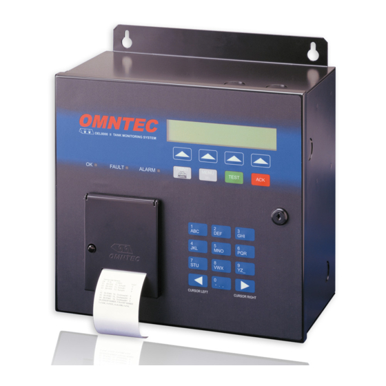
Omntec OEL8000II Manuals
Manuals and User Guides for Omntec OEL8000II. We have
2
Omntec OEL8000II manuals available for free PDF download: Installation Manual, Owner's Manual
Omntec OEL8000II Installation Manual (146 pages)
Brand:
Omntec
| Category:
Measuring Instruments
| Size: 1.15 MB
Table of Contents
Table of Contents
9
Read this First
13
Overview
19
System Description
19
Safety
19
Unpacking, Inspection and Damage Claims
20
Returns
21
Electrical Wiring
21
Wires and Cables
21
Conduits
22
Equipment
25
Controller
25
Preparation
25
BX-Series Sensor Worksheet
26
Tank Tilt
26
Controller Installation
27
Mounting the Controller
28
Wiring and Controller Knockout Designations
28
Junction Boxes
29
EYS Seal off Fitting
29
AC Power Line
30
Telephone Connections at the Controller
30
AC Power Connections at the Controller
30
Main Panel and Sub-Panel Grounding
31
Magnetostrictive (Mtg) Probe
31
MTG Probe Length
32
Riser Pipe for MTG Probe
32
Riser Pipe Minimum Length Requirements
33
Riser Pipe Maximum Length Requirements
33
MTG Probe Installation
34
MTG Probe Field Wiring
34
Probe Cable
35
MTG Probe Connections at the Controller
35
Sensors
36
Sensor Cable
37
BX-PDWF Sensor
37
Riser Pipe for BX-PDWF
38
BX-PDWF Installation
39
Bx-Pdws
40
Riser Pipe for BX-PDWS
40
BX-PDWS Installation
41
Bx-Pds
41
BX-L12, BX-L20, BX-LV Series
43
Riser Pipe for BX-L12, BX-L20, BX-LV Series
43
BX-L12, BX-L20, BX-LV Installation
43
BX-LM* Series
44
Riser Pipe for BX-LM* Series
44
BX-LM* Installation
44
Bx-Res
45
Riser Pipe for BX-RES
46
BX-RES Installation
46
Bx-Ls
47
Bx-Lsr
48
Bx-Lwf
48
Riser Pipe for BX-LWF
48
BX-LWF Installation
49
Bx-Tc
49
Bx-Vs
51
Field Wiring
51
Annunciators (RAS Series)
52
Mounting the Annunciator
53
Wiring for Annunciators
53
Wiring Configuration for Annunciators
54
Annunciator Connections at the Controller
55
Interface Boards (IB-Series)
56
Remote Communications
57
Applying Power
59
Preparations
59
Checklist
59
System Start-Up Checklist
60
Connecting Power
61
Programming
63
Preparation
63
Procedure
64
LCD Display
64
Tactile Keypad
64
Printer
65
Programming Procedures
65
Entering the SETUP Mode
67
Entering the Security Code
67
Location Data
70
Site Name
70
New Security Code
71
Preprogrammed Data
71
Site Address Line 1
72
Site Address Line 2
72
Site City
72
Site State
73
Site Zip Code
73
Site Phone Number
73
Site Manager's Name
74
Site Identification Number
74
Site Print Header
74
CITLD Enable Code
75
Ullage Percentage
75
Tank Data
76
Copying Tank Data
76
Tank Identification
78
Level Probe - Enable/Disable
78
Product Type
79
Coefficient of Thermal Expansion
79
Tank Tilt
80
Product Height
80
Water Height
81
Thermistor Type
82
Probe Wire Speed
82
High Water Alarm Point
83
Low/Low Product Alarm Point
83
Delivery Needed Alarm Point
84
Low Product Point
84
High Product Point
84
High Product Warning Point
85
Overfill Product Alarm Point
85
High/High Product Alarm Point
85
Tank Diameter
85
Probe Length
86
Tank Capacity
86
Volume Offset
86
Automated VLD (Volume Leak Detection Test)
87
Sudden Loss Limit
89
Sensor Data
90
Config (Sensor) Submenu
92
Sensor Labeling
93
Other Label
96
Editing Sensor Labels
97
Temperature Sensor Programming
99
Vapor Sensor Programming
100
Test/Del (Sensor) Submenu
103
Testing and Deleting Sensors
103
Setting Sensor Priority
105
Clearing Logs (Alarm, Drop, CITLD, and VLD)
107
Shift Data
108
Remote Data
110
Site Alarm Acknowledge Time
111
Remote Horn Timeout
111
Remote Horn Time Enable/Disable
112
Comm
113
Serial
113
Com1
114
Com2
115
Com3
118
Modem
119
Autofax and Datamodem
120
Ip Modem
122
Rs485
122
Int Brd
123
Programming the IB-RB2 Relay Board
124
4.3.10.1.1 Tank Activation
126
Sensor Activation (Non-Product Distinguishing)
127
Sensor Activation (Product Distinguishing)
127
4.3.10.1.4 Temperature (BX-TC) Sensor Activation
128
Programming the IB-C420 Board
129
Programming the IB-12V Low Voltage Board
130
Programming the IB-NET Board
130
Report
130
Units
131
Language
132
Procedures
133
Loopback Test
133
Setting Product and Water Height (Calibration)
133
O Ndemand Vld Testing
133
Remote Testing of Ras Annunciator
133
Replacing Controller Batteries
133
Troubleshooting Sensors
134
Condition #1
134
Condition #2
134
Troubleshooting Probe Guide
135
Condition #1 - Status: High Water
135
Condition #3 - Status: Timeout Error on One Probe
136
Appendix G Modem
138
Advertisement
Omntec OEL8000II Owner's Manual (63 pages)
Brand:
Omntec
| Category:
Measuring Instruments
| Size: 0.41 MB
Table of Contents
Table of Contents
9
Read this First
11
Introduction
13
The Oel8000Ii
13
About this Manual
13
Manual Conventions
14
System Description
15
Main Functions
15
System Components
15
Controller
15
Controller Front Panel Features
16
Self Test
16
Warnings, Alarms, and Setpoints
17
Inventory Management
19
Volumetric Leak Detection (VLD)
20
System of Measurement
20
Communications
21
Probes
21
Sensors
21
Optional Features
21
Annunciators (RAS-Series Remotes)
21
Interface Boards
22
Remote Communications (OMNTEC-PC Interactive Software)
22
Additional Options
22
System Operations
23
Control Panel
23
LCD Display Screen
23
Leds
24
Arrow Keys
24
Function Keys (PRINT, MENU, TEST, and ACK)
24
PRINT Key
25
MENU/DELETE Key
25
TEST Key
25
ACK Key
26
Data Keypad
26
Printer
26
Lock and Keys
27
Horn
27
Menus, Screens, and Printouts
27
MAIN Menu
27
Screen #1 (MAIN Menu)
27
Screen #2 (MAIN Menu)
29
Screen #3 (MAIN Menu)
30
Screen #4 (MAIN Menu)
30
Screen #5 (MAIN Menu)
31
Screen #6 (Main Menu)
32
Submenus
32
STATUS Submenu
32
ALARMS Submenu
37
SETUP Submenu
39
TIME Submenu
39
ALRM LOG Submenu
40
ALRM PRNT Submenu
41
VLD Submenu
41
DROP E/D Submenu
43
PRNT DROP Submenu
44
TMP SNSR Submenu
45
SHIFT LOG Submenu
46
DIAG Submenu
47
PRINTER Submenu
49
Functions and Procedures
51
Basic Functions and Procedures
51
Printouts
51
System Inventory Printout
51
Inventory Printout for Specific Tank
51
Printout of Alarms and Warnings in Effect
51
View/Print Alarm Log
52
Printout Drop Information
52
Printout Shift Log Report
52
Enable/Disable Automatic Printout for Alarm
52
Enable/Disable Automatic Printout Upon Drop
53
View Inventory Data
53
View Alarms Currently in Effect
53
System Setup
53
Changing the Date and Time
53
Perform VLD
54
Enable/Disable Communications
54
Testing Alarms for Product and Water
54
Data Direction
54
Remote Testing of RAS Annunciator
54
Responding to Alarms
54
Faults
56
Testing Systems
56
Lcd Fields in Main Menu
56
Faq's for Oel8000Ii
59
Frequently Asked Questions
59
Installing Thermal Paper in the Printer
61
Appendix Belectrical Ratings
63
Electrical Ratings for the Oel8000Ii
63
Advertisement
Related Products
Omntec PROTEUS OEL8000III Series
Omntec Proteus OEL8000III-B
Omntec Proteus OEL8000III-K
Omntec Proteus OEL8000III-X
Omntec DI00010
Omntec DI00011
Omntec FuelCheck
Omntec PROTEUS B
Omntec PROTEUS K
Omntec Proteus Series
Omntec Categories
Measuring Instruments
Monitor
Security System
More Omntec Manuals
Login
Sign In
OR
Sign in with Facebook
Sign in with Google
Upload manual
Upload from disk
Upload from URL