Table of Contents
Advertisement
OMNTEC
1993 Pond Rd., Ronkonkoma, NY 11779
Phone 631-981-2001
®
Mfg., Inc.
Tank Gauging • Liquid Level and Leak Detection Systems •
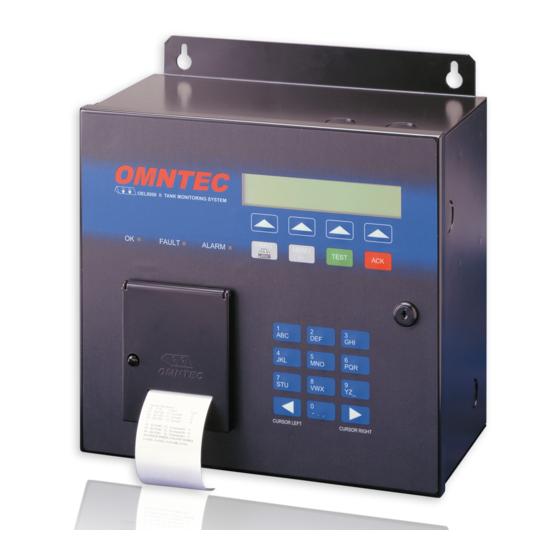
OEL8000II
Owner's Manual
OMNTEC
O E L 8 0 0 O I I T A N K M O N I T O R I N G S Y S T E M
PRINT
OK
FAULT
ALARM
Version 5.33E
Fax 631-981-2007
MENU
TEST
ACK
DEL
1
2
3
ABC
DEF
GHI
4
5
6
JKL
MNO
PQR
7
8
9
STU
VWX
YZ_
0
- . ,
CURSOR LEFT
CURSOR RIGHT
August 2006
e-mail:
support@omntec.com
www.OMNTEC.com
Advertisement
Table of Contents

Related Manuals for Omntec OEL8000II


Summary of Contents for Omntec OEL8000II
- Page 1 Mfg., Inc. 1993 Pond Rd., Ronkonkoma, NY 11779 Tank Gauging • Liquid Level and Leak Detection Systems • OEL8000II Owner’s Manual OMNTEC O E L 8 0 0 O I I T A N K M O N I T O R I N G S Y S T E M...
- Page 3 OEL8000II PROPRIETARY INFORMATION NOTICE ® This document contains information and material developed by OMNTEC Mfg., Inc. All rights are reserved. No part of this document may be reproduced, transmitted, processed or recorded by any means or form, electronic, mechanical, photographic or otherwise, without the express written consent of OMNTEC®...
- Page 5 OEL8000II NOTICE Use of unauthorized parts in the OEL8000II system or modification to any parts of the ® system will nullify U.L. listing and our warranty. OMNTEC Mfg., Inc. will not be responsible for any liability claims arising from the performance of modified units.
- Page 7 OEL8000II WARRANTY The seller, OMNTEC Mfg., Inc. warrants to buyer that product is free of defects when properly installed and maintained by user. Warranty period is one year from date of installation or 15 months from date of shipment from factory, whichever occurs first. The seller’s sole obligation is to repair or replace parts found to be defective upon evaluation...
-
Page 9: Table Of Contents
2.2.3 Sensors ......................2-7 2.2.4 Optional Features..................... 2-7 2.2.4.1 Annunciators (RAS-series Remotes) ..............2-7 2.2.4.2 Interface Boards...................... 2-8 2.2.4.3 Remote Communications (OMNTEC-PC interactive software) ......2-8 2.2.4.4 Additional Options....................2-8 SECTION 3 SYSTEM OPERATIONS ............... 3-1 3.1 C ....................... 3-1 ONTROL ANEL 3.1.1 LCD Display Screen .................. - Page 10 AULTS 4.4 T ..................... 4-6 ESTING YSTEMS 4.5 LCD F MAIN M ..................4-6 IELDS IN SECTION 5 FAQ’S FOR OEL8000II ................. 5-1 ..................5-1 REQUENTLY SKED UESTIONS APPENDIX A INSTALLING THERMAL PAPER ............. A-1 A.1 I ............A-1 NSTALLING...
-
Page 11: Read This First
All work must be performed only by authorized personnel who are qualified using intrinsically safe design principles (NEC procedures) and are thoroughly familiar with the OEL8000II Installation Manual. At a minimum, it is the installer’s responsibility to be familiar with and to comply with intrinsic design principles as defined in the National Electrical Code. - Page 12 3. Power to the controller must be removed before installing or servicing the equipment. 4. The only adjustments that you are allowed to make are: a. Loading the printer paper. b. Programming the controller as described in this manual. ® OMNTEC Mfg., Inc.
-
Page 13: Introduction
The OEL8000II has been designed to be easy to use, but you can take full advantage of its capabilities by taking some time to read this manual. If you do nothing else, make certain that everyone who will have access to the controller reads the previous section –... -
Page 14: Manual Conventions
Provides instructions for replacing the printer’s paper. Appendix B Electrical Ratings for the Contains electrical rating data. OEL8000II Manual Conventions This manual uses the following conventions: ♦ Bold indicates emphasis or heading. ♦ Note is used to set off important information from the rest of the text. -
Page 15: System Description
System Components The OEL8000II consists of a controller panel and a combination of probes and sensors. The probes and sensors are installed in the storage tanks, interstitial spaces, piping sumps, double wall piping, dispenser pans, dykes, and observation wells for monitoring the tank contents and detecting leaks. -
Page 16: Controller Front Panel Features
♦ Lock and Keys The OEL8000II controller has with a lock to prevent internal tampering. The end- user is provided with two keys. Do not open the controller yourself. Only authorized and qualified professionals may service or install components in the OEL8000II system. -
Page 17: Warnings, Alarms, And Setpoints
Figure 2-1: Sample Self-Test Printout 2.2.1.3 Warnings, Alarms, and Setpoints The OEL8000II controller will respond to certain conditions by initiating an alarm, warning condition, or a programmed response when the product level rises or drops to a specific setpoint. The controller responds to a warning condition by displaying a message on its LCD. - Page 18 Sensor Level Product Product Needed Level Water Loss Alarm* Warning Alarm Alarm Level Level Alarm Alarm Alarm Alarm OEL8000II Piezo Horn OEL8000II Alarm LED OEL8000II Audible Alarm Display Remote Annunciator Alarm LED Flashing Remote Flashing Annunciator Solid LED Remote Illuminated...
-
Page 19: Inventory Management
Below (see Figure 2-2) is an example of the automatic printout (in this case shift #1 begins at noon and ends at 8:00 PM). Note: An authorized, qualified installer must program this feature. The installer should refer to the programming section in the OEL8000II Installation Manual. Owners Manual... -
Page 20: Volumetric Leak Detection (Vld)
OEL8000II Installation Manual. 2.2.1.6 System of Measurement The OEL8000II can be configured in the SETUP submenu to display data using either the standard English system of measurement or the Metric system, but not both. -
Page 21: Communications
2.2.3 Sensors The OEL8000II accepts up to a maximum of 44 Bright Eye series sensors (BX- series). BX-sensors are built with four-wire buss technology, which allows up to 22 BX-sensors to be networked along the same cable on each buss line. -
Page 22: Interface Boards
2.2.4.2 Interface Boards Optional alarm relays and low voltage annunciators can be integrated into the system to provide additional alert and control capability. The OEL8000II accepts up to six interface boards. ♦ Remote Annunciator Interface Boards (IB-RAS) ♦ Relay Boards (IB-RB2) ♦... -
Page 23: System Operations
SYSTEM OPERATIONS Control Panel The OEL8000II Controller is the heart of the entire system. In addition to monitoring probes and sensors, and providing warnings and alarms; it is used for programming the system, entering data, and retrieving data. The LCD display, LEDs, arrow keys, PRINT key, MENU/DELETE key, TEST key, ACK key, data keypad, printer, and panel lock are accessible on the Controller’s front panel (see Figure 3-1). -
Page 24: Leds
A function is an action key, such as MORE, which scrolls through the screens within a menu. 3.1.4 Function Keys (PRINT, MENU, TEST, and ACK) The PRINT, MENU/DELETE, TEST, and ACK keys are located directly below the arrow keys and have the following functions: ® OMNTEC Mfg., Inc. -
Page 25: Print Key
OEL8000II 3.1.4.1 PRINT Key Press the PRINT key to provide a printout of site data, alarm data for currently active alarms, and an inventory report. 3.1.4.2 MENU/DELETE Key MENU and DELETE appear on the same key. While in a submenu, pressing this key will return the LCD to one of the four Main Menu screens. -
Page 26: Ack Key
LCD. The printer can also be programmed to provide automatic printouts under certain conditions such as the occurrence of an alarm and when an alarm is acknowledged. Automatic printouts can also be obtained of DROP, Shift, and VLD reports. ® OMNTEC Mfg., Inc. -
Page 27: Lock And Keys
OEL8000II The FEED button on the printer is used to advance the paper. The message, Paper is out will appear on the LCD display when the paper runs out (to change paper, see Appendix A – Installing Thermal Paper). Note: Red margins will appear on the printer paper when the paper is starting to run low. - Page 28 ♦ MORE – advances to Screen #2 of the Main Menu, which provides additional options. Note: To return to a MAIN Menu screen, press the MENU key or select the EXIT function when it is displayed on the bottom line of the LCD. ® OMNTEC Mfg., Inc.
-
Page 29: Screen #2 (Main Menu)
OEL8000II 3.2.1.2 Screen #2 (MAIN Menu) Selecting MORE on the bottom line of the LCD, advances the LCD to Screen #2 (see Figure 3-4a). TU 02/06/07 15:24:31 *STATUS:NORMAL TIME |PRINT ALL |ALRM LOG |MORE Fig. 3-4a: Main Menu – Screen #2 (Status: Normal) The bottom line of the screen changes and provides the following additional options: ♦... -
Page 30: Screen #3 (Main Menu)
♦ CITLD – an optional feature for enabling Continuous In-Tank Leak Detection. It performs continuous (24-hour) in-tank leak detection by collecting data during tank idle time. Contact OMNTEC® Mfg., Inc. for additional information. ♦ MORE – advances to Main Menu Screen #4 for more options. -
Page 31: Screen #5 (Main Menu)
OEL8000II TU 02/06/07 15:24:31 *STATUS:NORMAL DROP E/D |PRNT DROP |TEMP SNSR |MORE Fig. 3-6: Main Menu – Screen #4 (Status: Normal) The bottom line of the screen changes and provides the following additional options: ♦ DROP E/D – permits enabling/disabling automatic printout whenever a delivery (DROP) occurs (see Section 3.2.2.8 –... -
Page 32: Screen #6 (Main Menu)
♦ CLD – allows you to perform Continuous Leak Detection, and is primarily used for leak testing sump and dispenser containment areas. This feature is discussed in detail in the OEL8000II Installation Manual. ♦ PRINTER – displays a submenu that allows you set the print direction. The choices are: no actions, paper, LCD, comm2, and comm3 (see Section 3.2.2.13 –... - Page 33 OEL8000II STATUS Menu, however, you may start with a different screen. This is because system will enter at the last STATUS screen viewed. Note: While in the STATUS Submenu, pressing the MENU key will return the LCD to Screen #1 of the MAIN Menu.
- Page 34 Selecting MORE on the bottom line of the LCD, advances the LCD to Screen #2 (see Figure 3-11) of the STATUS Submenu. TU 02/06/07 15:24:31 *STATUS:NORMAL Tank 1, VOLUME Prod: 2907.10 (G) WATER: 36.16 (G) Gross:2943.30 (G) NEXT |PREV. |PRINT |MORE Fig. 3-11: Status Submenu – Screen #2 ® 3-12 OMNTEC Mfg., Inc.
- Page 35 OEL8000II This screen provides product, water, and gross volume data for the tank number shown. The top line remains unchanged showing the day, date, time, and status. The next two lines provide the following data: ♦ VOLUME Prod – shows the product volume (gallons) in the tank.
- Page 36 The next two lines provide the following data: ♦ AVG T. – shows the current average temperature (°F) in the tank. ♦ T.C. – the caculated Temperature Compensated Product Volume to 60°F. ® 3-14 OMNTEC Mfg., Inc.
-
Page 37: Alarms Submenu
OEL8000II 3.2.2.2 ALARMS Submenu The ALARMS Submenu is entered from Screen #1 of the MAIN Menu by selecting ALARMS. It displays information pertaining to any alarms that currently exist. If ALARMS is selected when there is no alarm or warning condition, the LCD will remain in Screen #1 of the Main Menu and the second line will display a message that there are no active alarms (see Figure 3-15a). - Page 38 (or disabled) to provide an automatic printout upon the occurrence of an alarm or warning in the ALRM PRNT Submenu (see Section 3.2.2.6 ALRM PRNT Submenu) that can be accessed in Screen #3 of the MAIN Menu. ® 3-16 OMNTEC Mfg., Inc.
-
Page 39: Setup Submenu
The SETUP Submenu is entered from Screen #1 of the MAIN Menu by selecting SETUP. This section is discussed in the OEL8000II Installation Manual, and it can be accessed only by authorized installers. Entry is blocked by a security code. -
Page 40: Alrm Log Submenu
S#: 3, BXUT1 , S/N: 500064832 Tank#: 1, Interstic#: 1 SENSOR ALARM CLEARED Event Time: TU 02/06/07 10:56:08 DIESEL S#: 3, BXUT1 , S/N: 500064832 Tank#: 1, Interstic#: 1 ALARM! Event Time: TU 02/06/07 10:55:42 Figure 3-18b: Alarm Log ® 3-18 OMNTEC Mfg., Inc. -
Page 41: Alrm Prnt Submenu
OEL8000II The bottom line of the ALRM LOG Submenu provides the following features: ♦ PRINT LOG – select PRINT LOG to obtain a printout of the alarm log. ♦ BACK – allows you to return to Screen #2 of the MAIN Menu. - Page 42 Although the example below shows only one tank, the log will actually hold data for up to 32 reports. Once it has reached 32 reports, it will delete old data as new data is entered. ® 3-20 OMNTEC Mfg., Inc.
-
Page 43: Drop E/D Submenu
OEL8000II Procedure for running VLD tests Before running a VLD test for a specific tank, wait four (4) hours after a delivery to allow the contents to settle. Also, the tank must remain inactive for about 4.5 hours while the test is in progress. This assumes the test has been programmed for 4 hours and the dwell time has been programmed for 0.5 hours. -
Page 44: Prnt Drop Submenu
♦ ALL DROPS – provides printout of all drops in log (maximum of 5 drops per tank and 40 drops for the entire system). ♦ BACK – returns to Screen #4 of the MAIN Menu. ® 3-22 OMNTEC Mfg., Inc. -
Page 45: Tmp Snsr Submenu
OEL8000II ---Delivery Log TANK 1 PRODUCT TYPE :DIESEL Start Time: TH 01/11/07 12:00:01 Stop Time: TH 01/11/07 12:30:54 Start T.C. Vol.: 2666.06(G) Start Gross Vol.: 2673.27(G) Start Water Vol.: 191.37(G) Start Product Level: 39.56 (In) Start Water Level: 2.83 (In) Start Temperature: 66.47(F) -
Page 46: Shift Log Submenu
♦ ENTER – enter the number of shifts to be printed using data keypad then select ENTER to print the report and return to Screen #5 of the MAIN Menu. ♦ EXIT – returns to Screen #5 of the MAIN Menu. ® 3-24 OMNTEC Mfg., Inc. -
Page 47: Diag Submenu
OEL8000II .---Shift Log End Time FR 02/02/07 18:00:00 Start Time TH 02/01/07 12:00:00 Tank1, DIESEL End Product Level: 43.56(In) Start Product Level: 43.60(In) End Product Vol.: 2942.97(In) Start Product Vol.: 2945.66(In) End T.C. Vol.: 2934.10(G) Start T.C. Vol.: 2935.80(G) End Water Level: 2.90(In) - Page 48 1. Select water or product. LCD will display selected test (see Figures 3-25b and 3-25c). 2. Select EXIT. 3. Press the MENU key. 4. Select STATUS. The LCD will display the volume for water or product (whichever you selected in Step 1). ® 3-26 OMNTEC Mfg., Inc.
-
Page 49: Printer Submenu
OEL8000II 5. Use the CURSOR LEFT key or CURSOR RIGHT key to adjust height until alarm sounds. 6. Press the ACK key to acknowledge alarm and silence horn. 7. Return to the DIAG submenu screen, and select O (off), and select EXIT to exit the submenu. -
Page 51: Functions And Procedures
OEL8000II Section 4 FUNCTIONS and PROCEDURES Basic Functions and Procedures This section identifies commonly used functions and either provides instructions or directs you to the proper subsection in Section 3 – System Operations for additional information. 4.1.1 Printouts The following provides instructions for obtaining printouts and enabling/disabling printer for automatic printouts. -
Page 52: View/Print Alarm Log
The printer can be enabled or disabled to provide an automatic printout upon the occurrence of an alarm. Starting in Screen #1 of the MAIN Menu, do the following: 1. Select MORE (two times) to advance to Screen #3. ® OMNTEC Mfg., Inc. -
Page 53: Enable/Disable Automatic Printout Upon Drop
In Screen #1 of the MAIN Menu, select ALARMS (see Section 3.2.2.2 – ALARMS Submenu). 4.1.4 System Setup System setup occurs in the SETUP Submenu, which is discussed in the OEL8000II Installation Manual. It is accessible only to authorized, qualified personnel. 4.1.5 Changing the Date and Time The data and time are changed in the TIME Submenu. -
Page 54: Perform Vld
For remote testing, press and release the horn silence button on the annunciator itself. Lights will blink and horn will sound on both the controller and the annunciator. Responding to Alarms The following procedure describes how to respond to alarms and retrieve alarm data. ® OMNTEC Mfg., Inc. - Page 55 OEL8000II 1. When the green OK LED is illuminated, the TU 02/06/07 15:24:31 *STATUS:NORMAL system is operating properly and no alarm conditions exist. STATUS |ALARMS |SETUP |MORE FAULT ALARM 2. When an alarm condition occurs: ♦ Horn will sound. TU 02/06/07...
-
Page 56: Faults
8. VLD – enters volumetric leak detection procedure. 9. CITLD – Continuous In-Tank Leak Detection. Contact OMNTEC® Mfg., Inc. for additional information. 10. Drop E/D – enables printer to provide an automatic printout following a delivery. - Page 57 13. Shift Log – prints shift log. 14. Diag – enables/disables callout and tests alarm levels for product and water. 15. CLD – Continuous Leak Detection. Discussed in the OEL8000II Installation Manual. 16. Printer – directs data to printer, LCD, etc.
-
Page 59: Faq's For Oel8000Ii
FAQ’s for OEL8000II Frequently Asked Questions The following are frequently asked questions and answers for the OEL8000II: Q1. What cable should be used for tanks and sensors? A1. Belden 8761 for probes (a must) and Belden 9940 for sensors (recommended). - Page 60 FAQ’s for OEL8000II Q7. What does sudden loss alarm refer to? A7. Product was dispensed during VLD test. Q8. How do you clear sudden loss alarm on the LCD? A8. Clear RAM. Q9. Is it necessary to reprogram system after clearing RAM? A9.
-
Page 61: Installing Thermal Paper In The Printer
OEL8000II Appendix A INSTALLING THERMAL PAPER Installing Thermal Paper in the Printer The following procedure provides instructions for replacing the printer’s thermal paper. The circled numbers in the diagrams refer to the instruction numbers where parts are identified.. 1. Life printer cover (see Figure A-1). - Page 62 FAQ’s for OEL8000II OMNTEC O E L 8 0 0 O I I T A N K M O N I T O R I N G S Y S T E M 7. While lowering the print cover, feed the paper...
-
Page 63: Appendix Belectrical Ratings
OEL8000II Appendix B ELECTRICAL RATINGS Electrical Ratings for the OEL8000II MODEL OEL8000II TANK GAUGING LEAK DETECTION CONTROLLER SERIAL NUMBER ______________________ LISTED 5L04 Associated Apparatus; non-hazardous locations; [AEx ia] IIB; [Ex ia] IIB provides intrinsically safe outputs for use in Class I, Div.1, Groups C and D or Class I Zone O, Group IIB hazardous...
Need help?
Do you have a question about the OEL8000II and is the answer not in the manual?
Questions and answers