
Related Manuals for Extreme Networks ExtremeSwitching SLX 9030 Series


Summary of Contents for Extreme Networks ExtremeSwitching SLX 9030 Series
- Page 1 HARDWARE INSTALLATION GUIDE ExtremeSwitching SLX 9030 Hardware Installation Guide 9035691-02 Rev AD February 2020...
- Page 2 Legal Notice Extreme Networks, Inc. reserves the right to make changes in specifications and other information contained in this document and its website without prior notice. The reader should in all cases consult representatives of Extreme Networks to determine whether any such changes have been made.
-
Page 3: Table Of Contents
Contents Preface..............................................7 Conventions..................................................7 Notes, cautions, and warnings........................................7 Text formatting conventions......................................... 7 Command syntax conventions........................................8 Documentation and Training..........................................8 Getting Help................................................. 8 Subscribe to Service Notifications......................................9 Providing Feedback..............................................9 About this Document........................................11 Supported hardware and software........................................11 What is new in this document..........................................12 Device Overview.......................................... - Page 4 Time and items required..........................................27 Parts list................................................27 Flush-front mounting........................................... 28 Installing the Universal Two-Post Rack Kit (XEN-R000294)..............................31 Installation requirements..........................................32 Time and items required..........................................32 Parts list ................................................32 Flush-front mounting........................................... 33 Mid-mounting..............................................37 Installing the Universal Four-Post Rack Kit (XEN-R000296).............................41 Installation requirements..........................................
- Page 5 Identifying the airflow direction..........................................86 Time and items required............................................86 Replacing a power supply............................................86 Inserting a new AC power supply ........................................87 Inserting a new DC power supply........................................88 Grounding the SLX 9030/9030-T device....................................89 Fan Assemblies..........................................91 Fan assemby overview............................................91 Precautions specific to fan assemblies......................................92 Identifying the airflow direction..........................................93 Times and items required............................................
- Page 6 ExtremeSwitching SLX 9030 Hardware Installation Guide 9035691-02 Rev AD...
-
Page 7: Preface
Preface • Conventions..........................................7 • Documentation and Training....................................8 • Getting Help..........................................8 • Providing Feedback......................................9 This section describes the text conventions used in this document, where you can find additional information, and how you can provide feedback to us. Conventions This section discusses the conventions used in this guide. -
Page 8: Command Syntax Conventions
Data Center products Other resources, like white papers, data sheets, and case studies Extreme Networks offers product training courses, both online and in person, as well as specialized certifications. For details, visit www.extremenetworks.com/education/. Getting Help If you require assistance, contact Extreme Networks using one of the following methods: Extreme Portal Search the GTAC (Global Technical Assistance Center) knowledge base;... -
Page 9: Subscribe To Service Notifications
Providing Feedback The Information Development team at Extreme Networks has made every effort to ensure the accuracy and completeness of this document. We are always striving to improve our documentation and help you work better, so we want to hear from you. We welcome all feedback, but we especially want to know about: •... - Page 10 ExtremeSwitching SLX 9030 Hardware Installation Guide 9035691-02 Rev AD...
-
Page 11: About This Document
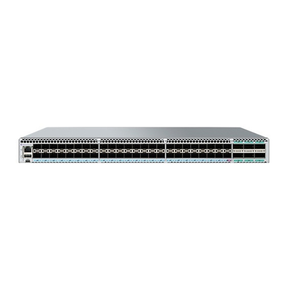
About this Document • Supported hardware and software................................11 • What is new in this document..................................12 Supported hardware and software The ExtremeSwitching SLX 9030 comes in two switch models, the SLX 9030-48S and the SLX 9030-48T models with high- performance, nonblocking network switching chipset with 880Gbps capacity. The switch supports 48x10G/1G (SFP+) + 4x100G/40G (QSFP+) (For SLX-9030-48S) or48x10G/1G/100M (RJ-45) + 4x100G/40G (QSFP+) (For SLX-9030-48T), a console port (RS232 in RJ45, 115200 bps) and management interface (RJ45 100/1000 Mbps). -
Page 12: What Is New In This Document
What is new in this document TABLE 3 Supported SLX 9030 Switch Power Supplies (continued) Part number Description Introduced OS Currently supported 10962 1100W DC power supply, Front-to-Back airflow SLX-OS 18x.1.00 10963 1100W DC power supply, Back-to-Front airflow SLX-OS 18x.1.00 The following table list the SLX 9030 Switch supported Fan modules. -
Page 13: Device Overview
Device Overview • ExtremeSwitching SLX 9030 platform introduction.......................... 13 • Hardware features......................................13 • Port-side view of the SLX 9030 series switches..........................14 • Nonport-side view of the SLX 9030 series switches ........................14 • Device management options..................................15 • Management commands....................................15 ExtremeSwitching SLX 9030 platform introduction The ExtremeSwitching SLX 9030 platform are high-performance 48-port 10GbE leaf switch that comes in two switch models, the SLX 9030-48S and the SLX 9030-48T with high-performance, nonblocking network switching chipset supporting up to 880 Gbps. -
Page 14: Port-Side View Of The Slx 9030 Series Switches
Port-side view of the SLX 9030 series switches SLX 9030-48S device front view The following shows the rear view of the SLX 9030-48S or SLX 9030-48T switch. SLX 9030 device rear view Port-side view of the SLX 9030 series switches The following illustration shows the port-side view of the SLX 9030 series switches. -
Page 15: Device Management Options
Management commands FIGURE 2 Nonport-side view Grounding lug AC power input connectors Fan modules Device management options You can use the management functions built into the device to monitor the port status, physical status, and other information to help you analyze device performance and to accelerate system debugging. - Page 16 Management commands NOTE The default is Auto Mode, but the user can override the default speed. (Mismatched speed configuration causes the link to be disabled and a RASLog message to be sent. device# show interface ethernet 0/51 Ethernet 0/51 is admin down, line protocol is down (admin down) Pluggable media present Interface index (ifindex) is 201744640 (0xc066100)
-
Page 17: Enabling Fec
Management commands FEC Mode - Disabled device# show ip interface brief • Interface IP-Address Status Protocol ================== ========== ================== ==================== ======== Ethernet 0/1 unassigned default-vrf administratively down down Ethernet 0/2 unassigned default-vrf administratively down down Ethernet 0/51:1 unassigned default-vrf administratively down down Ethernet 0/51:2 unassigned... -
Page 18: Verifying Hardware Profiles
Management commands Verifying media on an SLX 9030-48T: SLX# show media Interface Ethernet 0/1 Identifier On-board Connector CAT-5 copper cable Transceiver 10G BASE-T Gigabit Ethernet Name Encoding IEEE 802.3ab Length max 100 m Vendor Name EXTREME Vendor OUI 00:1b:e9 Verifying hardware profiles TCAM, LAG, Counter, Route, and CAM Share are profiles that are supported on the SLX 9030 series. -
Page 19: Preparing For The Installation
Preparing for the Installation • Safety precautions......................................19 • Facility requirements......................................21 • Quick installation checklist..................................... 23 • Shipping carton contents....................................24 Safety precautions When using this product, observe all danger, caution, and attention notices in this manual. The safety notices are accompanied by symbols that represent the severity of the safety condition When using this product, observe all danger, caution, and attention notices in this manual. -
Page 20: Esd Precautions
Safety precautions CAUTION Never leave tools inside the chassis. CAUTION If you do not install a module or a power supply in a slot, you must keep the slot filler panel in place. If you run the chassis with an uncovered slot, the system will overheat. CAUTION Use the screws specified in the procedure. -
Page 21: Lifting Precautions
Laser Radiation. Do Not View Directly with Optical Instruments. Class 1M Laser Products. DANGER Use only optical transceivers that are qualified by Extreme Networks, Inc. and comply with the FDA Class 1 radiation performance requirements defined in 21 CFR Subchapter I, and with IEC 60825 and EN60825. Optical products that do not comply with these standards might emit light that is hazardous to the eyes. -
Page 22: Environmental Considerations
Facility requirements • The supply circuit, line fusing, and wire size are adequate, as specified by the electrical rating on the device nameplate. • The power supply standards are met. Environmental considerations For successful installation and operation of the device, ensure that the following environmental requirements are met: •... -
Page 23: Quick Installation Checklist
Quick installation checklist • Plan for the rack space required for cable management before installing the device. • Leave at least 1 m (3.28 ft) of slack for each port cable. This provides room to remove and replace the device, allows for inadvertent movement of the rack, and helps prevent the cables from being bent to less than the minimum bend radius. -
Page 24: Shipping Carton Contents
Shipping carton contents Shipping carton contents When unpacking the device, verify that the contents of the shipping carton is complete. Save the shipping carton and packaging in the event you need to return the shipment. • The SLX 9030/9030-T Switch comes with an accessory kit containing the following items: –... -
Page 25: Mounting The Device
19 before mounting the device. NOTE These rack mount kits are supported for this device at the date of this publication. For the latest support information, contact your Extreme Networks representative. Mounting precautions The following precautions specifically apply to mounting the device. -
Page 26: Standalone Installation
Standalone installation CAUTION Use the screws specified in the procedure. Using longer screws can damage the device. CAUTION Do not install the device in an environment where the operating ambient temperature might exceed 50°C (122°F). Standalone installation Complete the following steps to install the device as a standalone unit on a table top. Unpack the device and verify the items listed under "Items included with this device"... -
Page 27: Four-Post Rack Mount Kit Installation (Xbr-R000297)
Four-post rack mount kit installation (XBR-R000297) To mount the product into a four-post rack using the included rack-mount kit, refer to “Four-post rack mount installation (XBR- R000297)” on page 27 for the installation procedure. Four-post rack mount kit installation (XBR-R000297) Use the following instructions to install the SLX 9030 or the SLX 9030-T Switch in EIA racks that are between 46 cm and 79 cm (18 to 31 in.) using the four-post flush-mount rack kit included with the switch. -
Page 28: Flush-Front Mounting
Four-post rack mount kit installation (XBR-R000297) FIGURE 3 Items in the four-post flush-mount rack kit Front brackets (2) Rear brackets, long (2) Screw, 10-32 x 5/8-in., panhead Phillips (12) Retainer nut, 10-32 (12) Ensure that the items listed and illustrated in Figure 3 are included in the kit. CAUTION Use the screws specified in the procedure. - Page 29 Four-post rack mount kit installation (XBR-R000297) Attaching the rear brackets to the rack posts on page 30 . Attaching the front brackets Complete the following steps to attach the front brackets to the device. Position the right front bracket with the flat side against the right side of the device at the front of the device, as shown in the figure below.
- Page 30 Four-post rack mount kit installation (XBR-R000297) Attach the left front bracket to the left front rack post using three 10-32 x 5/8-in. panhead screws and three retainer nuts. Use the three holes in the bracket. Tighten all the 10-32 x 5/8-in. screws to a torque of 25 in-lb (29 cm-kg). FIGURE 5 Installing the device in the rack Screws, 10-32 x 5/8-in., panhead Phillips Retainer nuts, 10-32...
-
Page 31: Installing The Universal Two-Post Rack Kit (Xen-R000294)
Installing the Universal Two-Post Rack Kit (XEN- R000294) Use the following instructions to install an Extreme Networks 1U or 2U device in a two-post telecommunications (Telco) rack using the Universal Two-Post Rack Kit (XEN-R000294). There are two ways you can mount the device in a two-post rack: •... -
Page 32: Installation Requirements
Installing the Universal Two-Post Rack Kit (XEN-R000294) • Hardware devices illustrated in these procedures are only for reference and may not depict the device you are installing in the rack. Installation requirements Review the installation and facility requirements for your product before mounting the device . Refer to the hardware installation guide for your product for more information. -
Page 33: Flush-Front Mounting
Installing the Universal Two-Post Rack Kit (XEN-R000294) FIGURE 7 XEN-R000294 Rack Parts list Front brackets (2) Rear brackets 5-6 inch post (2) Rear brackets 3-5 inch post (2) Screw, 8-32 x 5/16-in., panhead Phillips (8) Screw, 8-32 x 5/16-in., flathead Phillips (16) Screw, 6-32 x 1/4-in., panhead Phillips (8) Screw, 10-32 x 5/8-in., panhead Phillips (8) Retainer nut, 10-32 (8) - Page 34 Installing the Universal Two-Post Rack Kit (XEN-R000294) • The illustrations for this procedure show a two-post rack with narrow posts (3- to 5-inch) as an example. • The illustrations in the rack installation procedures are for reference only and may not show the actual device. Complete the following tasks to install the device in a rack: Attaching the front brackets to the device on page 34...
- Page 35 Installing the Universal Two-Post Rack Kit (XEN-R000294) Attaching the front brackets to the rack Complete the following steps to install the device in the rack. Position the device in the rack, as shown in (Figure 9), providing temporary support under the device until the rack kit is fully secured to the rack.
- Page 36 Installing the Universal Two-Post Rack Kit (XEN-R000294) Tighten all the 10-32 x 5/8-in. screws to a torque of 25 in-lb. (29 cm-kg). FIGURE 10 Attaching the rear brackets to a rack Retainer nuts, 10-32 Screws, 10-32 x 5/8-in., panhead Phillips Rear brackets Attaching the rear brackets to the device Complete the following steps to attach the rear brackets to the device.
-
Page 37: Mid-Mounting
Installing the Universal Two-Post Rack Kit (XEN-R000294) Tighten all the 8-32 x 5/16-in. screws to a torque of 15 in-lb (17 cm-kg). FIGURE 11 Attaching the rear brackets to the device Screws, 8-32 x 5/16-in., panhead Phillips Mid-mounting Observe the following notes when using this procedure: •... - Page 38 Installing the Universal Two-Post Rack Kit (XEN-R000294) Insert four 8-32 x 5/16-in. flathead screws through the vertically aligned holes in the bracket and then into the holes on the side of the device. Use the upper and lower screw holes, leaving the center holes empty. Repeat step 1 and step 2 to attach the left front bracket to the left side of the device.
- Page 39 Installing the Universal Two-Post Rack Kit (XEN-R000294) Tighten all the 10-32 x 5/8-in. screws to a torque of 25 in-lb (29 cm-kg). FIGURE 13 Attaching front brackets to a rack Screws, 10-32 x 5/8-in., panhead Phillips Retainer nuts, 10-32 Attaching the rear brackets to the rack Complete the following steps to attach the rear brackets to the rack.
- Page 40 Installing the Universal Two-Post Rack Kit (XEN-R000294) Tighten all the 10-32 x 5/8-in. screws to a torque of 25 in-lb (29 cm-kg). FIGURE 14 Attaching the rear brackets to a rack Retainer nuts, 10-32 Screws, 10-32 x 5/8-in., panhead Phillips Rear brackets (right and left) Attaching the rear brackets to the device Complete the following steps to attach the rear brackets to the device.
-
Page 41: Installing The Universal Four-Post Rack Kit (Xen-R000296)
Installing the Universal Four-Post Rack Kit (XEN-R000296) Tighten all the 8-32 x 5/16-in. screws to a torque of 15 in-lb (17 cm-kg). FIGURE 15 Attaching the rear brackets to the device Screws, 8-32 x 5/16-in., panhead Phillips Installing the Universal Four-Post Rack Kit (XEN- R000296) Use the following instructions to install 1U and 2U devices in EIA racks that are between L-12.7 to 81.28 cm deep (L-5.0 to 32.0 in.), where L is the chassis depth, using the Universal Four-Post Rack Kit (XEN-R000296). -
Page 42: Installation Requirements
Installing the Universal Four-Post Rack Kit (XEN-R000296) Note that if chassis depth (L) is less than 40.64 cm (16 in.), the chassis will not fit into a rack with a maximum depth of 81.28 cm (32 in.) using the universal four-post rack kit. The maximum rack depth for a chassis less than 40.64 cm (16 in.) is 81.28 cm (32 in.) minus the difference between the chassis depth and 40.64 cm (16 in.). - Page 43 Installing the Universal Four-Post Rack Kit (XEN-R000296) FIGURE 16 XEN-R000296 Rack Parts list Front brackets (2) Extension brackets, medium (2) Rear brackets, short (2) Rear brackets, long (2) Extension brackets, long (2) Screw, 8-32 x 5/16-in., panhead Phillips (8) Screw, 8-32 x 5/16-in., flathead Phillips (16) Screw, 8-32 x 5/16-in., flathead Phillips (16) Screw, 10-32 x 5/8-in., panhead Phillips (8) 10.
-
Page 44: Flush-Front Mounting
Installing the Universal Four-Post Rack Kit (XEN-R000296) Ensure that the items listed and illustrated in Figure 16 are included in the kit. Note that not all parts may be used with certain installations depending on the device type. CAUTION Use the screws specified in the procedure. Using longer screws can damage the device. - Page 45 Installing the Universal Four-Post Rack Kit (XEN-R000296) Tighten all the 8-32 x 5/16-in. screws to a torque of 15 in-lb (17 cm-kg). FIGURE 17 Attaching the front brackets The device Screws, 8-32 x 5/16-in., flathead Phillips Front brackets Attaching the bracket extensions to the device Complete the following steps to attach the extension brackets to the device.
- Page 46 Installing the Universal Four-Post Rack Kit (XEN-R000296) Tighten all the 8-32 x 5/16-in. screws to a torque of 15 in-lb (17 cm-kg). FIGURE 18 Attaching the bracket extensions to the device Bracket extension Screws, 8-32 x 5/16-in., flathead Phillips Installing the device in the rack Complete the following steps to install the device in the rack.
- Page 47 Installing the Universal Four-Post Rack Kit (XEN-R000296) Tighten all the 10-32 x 5/8-in. screws to a torque of 25 in-lb (29 cm-kg). FIGURE 19 Positioning the device in the rack Screws, 10-32 x 5/8-in., panhead Phillips Retainer nuts, 10-32 Attaching the rear brackets to the extensions Complete the following steps to attach the rear brackets to the extensions.
- Page 48 Installing the Universal Four-Post Rack Kit (XEN-R000296) Adjust the brackets to the rack depth and tighten all the 6-32 x 1/4-in. screws to a torque of 9 in-lb (10 cm-kg). FIGURE 20 Attaching the rear brackets to the extensions Rear brackets Screws, 6-32 x 1/4-in., panhead Phillips Attaching the rear brackets to the rack posts Complete the following steps to attach the rear brackets to the rack posts.
-
Page 49: Flush-Rear (Recessed) Mounting
Installing the Universal Four-Post Rack Kit (XEN-R000296) Tighten all the 10-32 x 5/8-in. screws to a torque of 25 in-lb (29 cm-kg). FIGURE 21 Attaching the rear brackets to the rack posts Screws, 10-32 x 5/8-in., panhead Phillips Retainer nuts, 10-32 Flush-rear (recessed) mounting The flush-rear (recessed) mounting is similar to the flush-front mounting except that the brackets are reversed on the device. - Page 50 Installing the Universal Four-Post Rack Kit (XEN-R000296) Attaching the front brackets to the rear of the device NOTE In this installation, the brackets are named as listed in the parts list even though the installation of the brackets is reversed from the flush-front installation.
- Page 51 Installing the Universal Four-Post Rack Kit (XEN-R000296) Repeat step 2 and step 3 to attach the left front bracket extension to the left side of the device. Tighten all the 8-32 x 5/16-in. screws to a torque of 15 in-lb (17 cm-kg). FIGURE 23 Attaching the bracket extensions to the device Extension brackets Screws, 8-32 x 5/16-in., flathead Phillips...
- Page 52 Installing the Universal Four-Post Rack Kit (XEN-R000296) Tighten all the 10-32 x 5/8-in. screws to a torque of 25 in-lb (29 cm-kg). FIGURE 24 Positioning the device in the rack Screws, 10-32 x 5/8-in., panhead Phillips Retainer nuts, 10-32 Attaching the rear brackets to the extensions at the front of the device Complete the following steps to attach the rear brackets to the extensions.
- Page 53 Installing the Universal Four-Post Rack Kit (XEN-R000296) Adjust the brackets to the rack depth and tighten all the 6-32 x 1/4-in. screws to a torque of 9 in-lb (10 cm-kg). FIGURE 25 Attaching the rear brackets to the extensions at the front of the device Rear brackets, short Screws, 6-32 x 1/4-in., panhead Phillips FIGURE 26 Attaching the short or long rear brackets to the extensions...
- Page 54 Installing the Universal Four-Post Rack Kit (XEN-R000296) Rear bracket, short or long Screws, 6-32 x 1/4-in., panhead Phillips Attaching the rear brackets to the front rack posts Complete the following steps to attach the rear brackets to the front rack posts. Attach the right rear bracket to the right front rack post using two 10-32 x 5/8-in.
-
Page 55: Initial Setup And Verification
Initial Setup and Verification • Initial setup and configuration checklist..............................55 • Items required........................................56 • Providing power to the device..................................56 • Establishing a serial connection ................................. 57 • Configuring a static IP address..................................59 • Establishing an Ethernet connection................................. 59 •... -
Page 56: Items Required
Items required TABLE 11 Initial setup and configuration checklist (continued) Task Task details or additional information • The following commands can be useful to establish an operational baseline for the device. Refer toExtreme SLX-OS Monitoring Configuration Guide for the SLX 9030/9030-T device for more information about these commands. -
Page 57: Establishing A Serial Connection
Establishing a serial connection NOTE Power is supplied to the device as soon as the first power supply is connected. After the device has booted, verify that the power and status LEDs are green. The power supply LEDs display amber until power-on self-test (POST) is complete, and then change to green. - Page 58 Establishing a serial connection Open a terminal emulator application (such as HyperTerminal on a PC, or TERM, Tip, or Kermit in a UNIX environment), and configure the application as follows: • In a Windows environment: Parameter Value Bits per second 115200 Data bits Parity...
-
Page 59: Configuring A Static Ip Address
Establishing an Ethernet connection Configuring a static IP address Complete the following steps to set a static IP address. NOTE You can also use DHCP to configure a chassis static IP address on the management module. Log in to the device using an account that has the admin role. Enter global configuration mode using the configure terminal command. -
Page 60: Customizing The Chassis And Host Names
Customizing the chassis and host names Perform the following steps to establish an Ethernet connection to the device. Remove the shipping plug from the Ethernet port on the active management module. The active management module has the LED labeled ACTIVE on the front panel illuminated in blue. Insert one end of an Ethernet cable into the Management Ethernet port. -
Page 61: Configuring The Dns Service
Verifying correct operation Change the chassis name by completing the following steps. Enter configure terminal to enter global configuration mode. Enter switch-attributes chassis-name chassis-name, where chassis-name is the new chassis name. Enter exit to return to privileged EXEC mode. To verify the new chassis name, enter the show chassis command. Change the host name by completing the following steps. -
Page 62: Setting The Date And Time
Setting the date and time Verify the correct operation of the device by entering the following commands. Copy output to a file to save the information. TABLE 12 Commands to verify correct operation Command Description show environment power Displays power supply status and information show environment fan Displays fans status and information show chassis or show system... -
Page 63: Installing Cable Management Kit
Installing cable management kit Installing cable management kit For more information about installing cable management, refer to managing cables section Managing cables on page 67 . ExtremeSwitching SLX 9030 Hardware Installation Guide 9035691-02 Rev AD... - Page 64 ExtremeSwitching SLX 9030 Hardware Installation Guide 9035691-02 Rev AD...
-
Page 65: Transceivers And Cables
Transceivers and Cables • Supported transceivers and cables................................65 • Time and items required....................................65 • Precautions specific to transceivers and cables............................66 • Cleaning the fiber-optic connectors................................66 • Managing cables........................................ 67 • Installing an SFP+ transceiver..................................67 • Replacing an SFP+ transceiver..................................69 •... -
Page 66: Precautions Specific To Transceivers And Cables
All fiber-optic interfaces use Class 1 lasers. DANGER Use only optical transceivers that are qualified by Extreme Networks, Inc. and comply with the FDA Class 1 radiation performance requirements defined in 21 CFR Subchapter I, and with IEC 60825 and EN60825. Optical products that do not comply with these standards might emit light that is hazardous to the eyes. -
Page 67: Managing Cables
Installing an SFP+ transceiver Managing cables The minimum radius that a 50 micron cable can be bent under full tensile load is 5.1 cm (2 in.). For a cable under no tensile load, that minimum is 3.0 cm (1.2 in.). Cables can be organized and managed in a variety of ways, for example, using cable channels on the sides of the rack or patch panels to minimize cable management. - Page 68 Installing an SFP+ transceiver NOTE Always use the pull tab to insert or remove transceivers as they might be hot. Perform one of the following steps, depending on your transceiver type. • If the transceiver uses a pull tab, use the pull tab to help push the transceiver into the port until it is firmly seated and the latching mechanism clicks.
-
Page 69: Replacing An Sfp+ Transceiver
Replacing an SFP+ transceiver FIGURE 32 Installing an SFP+ transceiver with bail latch into the interface module port Bail Transceivers are keyed so that they can only be inserted with the correct orientation. If a transceiver does not slide in easily, ensure that it is correctly oriented. - Page 70 Replacing an SFP+ transceiver To remove the transceiver, perform one of the following steps, depending on your transceiver type. • If transceiver has a bail latch mechanism (10 GbE transceivers), unlatch from the port by pulling the bail (wire handle) away from its pivot point using your fingers or the hooked end of the transceiver extraction tool.
-
Page 71: Installing A Qsfp28 Transceiver
Installing a QSFP28 transceiver FIGURE 34 Replacing a SFP+ optical transceiver with pull tab into the interface module port Pull tab Transceiver To install the transceiver, perform one of the following steps depending on your transceiver type: • If transceiver has a pull tab, use the pull tab to help push the transceiver into the port until it is firmly seated and the latching mechanism clicks. - Page 72 Installing a QSFP28 transceiver To insert an QSFP28 transceiver and cable, complete the following steps. Push the transceiver into the port using the pull tab. Transceivers are keyed so that they can only be inserted with the correct orientation. If a transceiver does not slide in easily, ensure that it is correctly oriented. Push the correctly oriented transceiver into the port until it is firmly seated and the latching mechanism clicks.
-
Page 73: Replacing A Qsfp28 Transceiver
Replacing a QSFP28 transceiver Replacing a QSFP28 transceiver Complete the following steps to remove and then install a new QSFP28 transceiver. Remove any cables that are inserted into the transceiver. NOTE If your transceiver has an integrated cable, you cannot remove the cable. Grasp the transceiver pull tab and gently pull the transceiver straight out from the port. -
Page 74: Breakout Cables
Breakout cables Position a cable so that the key (the ridge on one side of the cable connector) is aligned with the slot in the transceiver. Insert the cable into the transceiver until the latching mechanism clicks. NOTE If your transceiver has an integrated cable attached, you will not install a cable. When both ends of the cable are inserted and the link is fully established, the LED displays steady green. -
Page 75: Verifying Transceiver Operation
Verifying transceiver operation Verifying transceiver operation To verify operation of a transceiver, view the LEDs on the transceiver. To find the LED locations on the interface modules, refer to the section LED ports behavior on page 79. After you have connected and configured the ports for Ethernet connectivity and connected the cable to another active port, the LED becomes solid green. - Page 76 ExtremeSwitching SLX 9030 Hardware Installation Guide 9035691-02 Rev AD...
-
Page 77: Monitoring The Device
Monitoring the Device • Monitoring Overview......................................77 • LED Types..........................................77 • LED ports behavior......................................79 Monitoring Overview The Extreme device is engineered for reliability and requires no routine operational steps or maintenance. You can monitor the device by paying attention to the following information: •... - Page 78 LED Types FIGURE 38 System LEDs The following Table defines the per device LEDs' behaviors. TABLE 13 System LEDs Definition and Behavior Items LED Indication Color Behavior Description MGMT System No Powe Green Solid Light Normal Operation Amber Blinking Power supply failed or Fan module failed Green Light off No packet transmitting or receiving...
-
Page 79: Led Ports Behavior
LED ports behavior LED ports behavior This section details the behavior of the SLX 9030 device port LEDs. FIGURE 39 Port LEDs SLX 9030 Switch LED Behavior for Each Port (1~48 Ethernet Ports - top to bottom) are as follows: TABLE 14 SLX 9030 device LEDs behavior for ports 1–48 Speed, bps LED indication... - Page 80 LED ports behavior TABLE 14 SLX 9030 device LEDs behavior for ports 1–48 (continued) Speed, bps LED indication Color Behavior Description Blinking Port is sending or receiving data at 10 Gbps 1 G/100 M Amber Solid RJ-45 or SFP+ cable is correctly installed.
- Page 81 LED ports behavior FIGURE 40 Detail LED Definition for QSFP28 port ExtremeSwitching SLX 9030 Hardware Installation Guide 9035691-02 Rev AD...
- Page 82 ExtremeSwitching SLX 9030 Hardware Installation Guide 9035691-02 Rev AD...
-
Page 83: Power Supplies
If the second power supply and sixth fan assembly slots are unused, you must cover them with filler panels. NOTE Extreme Networks recommends that the SLX 9030/9030-T device operate with two power supplies and six fan assemblies installed. If a power supply or fan assembly fails, it must be replaced as soon as possible. - Page 84 Power supply overview FIGURE 41 AC power supply Release lever Power supply handle ExtremeSwitching SLX 9030 Hardware Installation Guide 9035691-02 Rev AD...
-
Page 85: Precautions Specific To Power Supplies
Precautions specific to power supplies FIGURE 42 DC power supply Release lever Power supply handle Precautions specific to power supplies DANGER Make sure that the power source circuits are properly grounded, then use the power cord supplied with the device to connect it to the power source. -
Page 86: Identifying The Airflow Direction
Identifying the airflow direction CAUTION Ensure that the airflow direction of the power supply unit matches that of the installed fan tray. The power supplies and fan trays are clearly labeled with either a green arrow with an "E", or an orange arrow with an "I." CAUTION If you do not install a module or a power supply in a slot, you must keep the slot filler panel in place. -
Page 87: Inserting A New Ac Power Supply
Inserting a new AC power supply • The airflow direction of the power supply must match that of the installed fan assemblies. All must be either exhaust or intake. NOTE Power supplies are hot-swappable. However, they should be inserted or removed without a power cord being connected to a power source to avoid damage. -
Page 88: Inserting A New Dc Power Supply
Inserting a new DC power supply When the SLX 9030/9030-T device is powered on, the LEDs on the power supply rear panel should light up green to confirm that the power supply is correctly installed and supplying power. NOTE If you do not install a power supply in a slot, you must keep the slot filler panel in place. If you run the device with an uncovered slot, the system will overheat. -
Page 89: Grounding The Slx 9030/9030-T Device
Grounding the SLX 9030/9030-T device Remove the previously installed power supply from the appropriate slot by pressing the release lever and pulling the power supply handle. Before opening the package that contains the DC power supply, touch the bag of the switch casing to discharge any potential static electricity. - Page 90 Grounding the SLX 9030/9030-T device FIGURE 46 Connecting the grounding terminal Grounding terminal NOTE The grounding lug must be sized according to NEC/CEC requirements. A typical installation would require: Lug, copper, suitable wire size, #10 2-hole, 5/8" centers. For #10 ga. Wire, example lugs are: •...
-
Page 91: Fan Assemblies
If the second power supply and sixth fan slots are unused, you must cover them with filler panels. NOTE Extreme Networks recommends that the SLX 9030/9030-T device operate with two power supplies and six fan assemblies installed. If a power supply or fan assembly fails, it must be replaced as soon as possible. -
Page 92: Precautions Specific To Fan Assemblies
Precautions specific to fan assemblies FIGURE 47 Fan assembly Captive screw Fan assembly handle Precautions specific to fan assemblies DANGER Be careful not to accidently insert your fingers into the fan tray while removing it from the chassis. The fan may still be spinning at a high speed. -
Page 93: Identifying The Airflow Direction
Inserting a new fan assembly Identifying the airflow direction The power supply and fan assemblies are identified by the following airflow directions: • Intake power supply and fan assembly with an orange "I" label or without any label: Pulls air from the nonport-side of the switch and exhausts it out the port side. - Page 94 Inserting a new fan assembly FIGURE 48 Installing a fan assembly Fan assembly slot Captive screw Fan assembly If replacing a fan assembly: Using a Phillips screwdriver, unscrew the captive screw on the fan assembly. Remove the fan assembly from the chassis by pulling the handle on the fan assembly out and away from the chassis. Ensure that the replacement fan assembly has the same part number and airflow label as the fan assembly being replaced.
- Page 95 Inserting a new fan assembly When a fan assembly is installed in a slot, the power LED on the fan assembly should turn on green to confirm that the fan assembly is correctly installed and running. Refer to “LED activity interpretation” on page 45. CAUTION If you do not install a module or a power supply in a slot, you must keep the slot filler panel in place.
- Page 96 ExtremeSwitching SLX 9030 Hardware Installation Guide 9035691-02 Rev AD...
-
Page 97: Extremeswitching Slx 9030 Technical Specifications
ExtremeSwitching SLX 9030 Technical Specifications SLX 9030 Switch Specifications System component Description Enclosure Chassis-mountable on a desktop, or in a standard 2 or 4-post rack kit Ports SLX 9030-48S amd SLX 9030-48T Switch Models • 48 1Gb/10Gb SFP+ ports • 2 10Gb/40Gb QSFP+ ports •... -
Page 98: Power And Heat Dissipation
Power and Heat Dissipation Power and Heat Dissipation Switch Model Minimum Heat Minimum Power Maximum Heat Maximum Power Dissipation Consumption Dissipation Consumption (BTU/hr) (Idle, (Watts) (Idle, no (BTU/hr) (Fans (Watts) (Fans high, no ports linked) ports linked) high, all ports all ports 100% 100% traffic) traffic) -
Page 99: Slx 9030 Software Specifications
LEDs SLX 9030 Software Specifications Software Specifications Description Connector Options • 10/1 GbE SFP+ • 40GbE QSFP+ • 100GbE QSFP-28 • Out-of-band Ethernet management: 10/100/1000 Mbps RJ-45 • Console management:RJ45 serial port and USB type-C port with serial communication device class support •... -
Page 100: Other
Other System component Description • LED 1: Green and LED 2: Flashing Yellow/Green - Over-temperature warning or fan error Fan module LEDs • Power (Fan) LED: No light (LED is off) - Fan assembly does not have power. Steady green - Fan assembly has power. -
Page 101: Serial Port Specifications (Pinout - Mini-Usb)
Regulatory compliance (EMC) Signal Description Transmit data Not supported Not supported Serial port specifications (pinout - mini-USB) Signal Description Reserved Not used UART0_RX Debug port (data received by SLX) UART0_TX Console port (data transmitted by SLX) Reserved Not used Ground Serial port specifications (protocol) Parameter Value... -
Page 102: Regulatory Compliance (Safety)
Regulatory compliance (safety) • KN 32 • KN 35 • TCVN 7189 • EN 61000-3-2 • EN 61000-3-3 • GB 9254 • CISPR 32 • 2014/30/EU • AS/NZS CISPR32 (Australia) (Class A) Regulatory compliance (safety) • EN/UL 60825 • EN/UL/CSA/IEC 60950-1 •... -
Page 103: Regulatory Statements
Regulatory Statements • CE statement........................................103 • China ROHS........................................103 • BSMI statement (Taiwan).....................................103 • Canadian requirements....................................104 • China CCC statement....................................104 • Europe and Australia (CISPR 32 Class A Warning)......................... 105 • FCC warning (US only)....................................105 • Germany statement....................................... 105 •... -
Page 104: Canadian Requirements
Canadian requirements This is Class A product. In a domestic environment this product may cause radio interference in which case the user may be required to take adequate measures. Canadian requirements This Class A digital apparatus meets all requirements of the Canadian Interference-Causing Equipment Regulations, ICES-003 Class A. Cet appareil numérique de la classe A est conforme à... -
Page 105: Europe And Australia (Cispr 32 Class A Warning)
KCC statement (Republic of Korea) Europe and Australia (CISPR 32 Class A Warning) This is a Class A product. In a domestic environment this product may cause radio interference in which case the user may be required to take adequate measures. FCC warning (US only) This equipment has been tested and complies with the limits for a Class A computing device pursuant to Part 15 of the FCC Rules. -
Page 106: Vcci Statement
VCCI statement VCCI statement This is a Class A product based on the standard of the Voluntary Control Council for Interference by Information Technology Equipment (VCCI). If this equipment is used in a domestic environment, radio disturbance might arise. When such trouble occurs, the user might be required to take corrective actions. -
Page 107: Cautions And Danger Notices
Cautions and Danger Notices • Cautions..........................................107 • Danger Notices........................................110 Cautions A Caution statement alerts you to situations that can be potentially hazardous to you or cause damage to hardware, firmware, software, or data. Ein Vorsichthinweis warnt Sie vor potenziellen Personengefahren oder Beschädigung der Hardware, Firmware, Software oder auch vor einem möglichen Datenverlust Un message de mise en garde vous alerte sur des situations pouvant présenter un risque potentiel de dommages corporels ou de dommages matériels, logiciels ou de perte de données. - Page 108 Cautions PRECAUCIÓN Asegúrese de que el flujo de aire en las inmediaciones de las partes anterior, laterales y posterior del instrumento no esté restringido. CAUTION Ensure that the airflow direction of the power supply unit matches that of the installed fan tray. The power supplies and fan trays are clearly labeled with either a green arrow with an "E", or an orange arrow with an "I."...
- Page 109 Cautions CAUTION Do not install the device in an environment where the operating ambient temperature might exceed 50°C (122°F). VORSICHT Das Gerät darf nicht in einer Umgebung mit einer Umgebungsbetriebstemperatur von über 50°C (122°F) installiert werden. MISE EN GARDE N'installez pas le dispositif dans un environnement où la température d'exploitation ambiante risque de dépasser 50°C (122°F).
-
Page 110: Danger Notices
Danger Notices PRECAUCIÓN Use un circuito derivado separado para cada cordón de alimentación, con lo que se proporcionará redundancia en caso de que uno de los circuitos falle. CAUTION Ensure that the device does not overload the power circuits, wiring, and over-current protection. To determine the possibility of overloading the supply circuits, add the ampere (amp) ratings of all devices installed on the same circuit as the device. -
Page 111: General Dangers
Danger Notices Ein Gefahrenhinweis warnt vor Bedingungen oder Situationen die tödlich sein können oder Sie extrem gefährden können. Sicherheitsetiketten sind direkt auf den jeweiligen Produkten angebracht um vor diesen Bedingungen und Situationen zu warnen. Un énoncé de danger indique des conditions ou des situations potentiellement mortelles ou extrêmement dangereuses. Des étiquettes de sécurité... - Page 112 Danger Notices DANGER Make sure that the power source circuits are properly grounded, then use the power cord supplied with the device to connect it to the power source. GEFAHR Stellen Sie sicher, dass die Stromkreise ordnungsgemäß geerdet sind. Benutzen Sie dann das mit dem Gerät gelieferte Stromkabel, um es an die Srromquelle anzuschließen.
- Page 113 Danger Notices PELIGRO Si la instalación requiere un cordón de corriente distinto al que se ha suministrado con el instrumento, verifique que usa un cordón de corriente que venga con la marca de la agencia de seguridad que defina las regulaciones para cordones de corriente en su país.
- Page 114 警告 DANGER Use only optical transceivers that are qualified by Extreme Networks, Inc. and comply with the FDA Class 1 radiation performance requirements defined in 21 CFR Subchapter I, and with IEC 60825 and EN60825. Optical products that do not comply with these standards might emit light that is hazardous to the eyes.
Need help?
Do you have a question about the ExtremeSwitching SLX 9030 Series and is the answer not in the manual?
Questions and answers