EWM tigSpeed continuous drive 45 coldwire Operating Instructions Manual
Wire feed unit
Hide thumbs
Also See for tigSpeed continuous drive 45 coldwire:
- Operating instructions manual (57 pages) ,
- Operating instructions manual (75 pages) ,
- Operating instructions manual (73 pages)

Related Manuals for EWM tigSpeed continuous drive 45 coldwire


Summary of Contents for EWM tigSpeed continuous drive 45 coldwire
- Page 1 Operating instructions Wire feed unit tigSpeed continuous drive 45 coldwire 099-000237-EW501 Observe additional system documents! 25.04.2019...
- Page 2 +49 2680 181-0. A list of authorised sales partners can be found at www.ewm-group.com/en/specialist-dealers. Liability relating to the operation of this equipment is restricted solely to the function of the equipment. No other form of liability, regardless of type, shall be accepted.
-
Page 3: Table Of Contents
Contents Notes on the use of these operating instructions Contents 1 Contents ..............................3 2 For your safety ............................6 Notes on the use of these operating instructions ................6 Explanation of icons ........................7 Part of the complete documentation ....................8 Safety instructions .......................... - Page 4 Error messages ..........................57 Resetting welding parameters to the factory settings ..............58 Vent coolant circuit ........................59 8 Technical data............................60 tigSpeed continuous drive 45 coldwire ..................60 9 Accessories ............................61 Options ............................61 General accessories ........................61 10 Replaceable parts ..........................
- Page 5 Contents Notes on the use of these operating instructions 099-000237-EW501 25.04.2019...
-
Page 6: For Your Safety
For your safety Notes on the use of these operating instructions For your safety Notes on the use of these operating instructions DANGER Working or operating procedures which must be closely observed to prevent imminent serious and even fatal injuries. •... -
Page 7: Explanation Of Icons
For your safety Explanation of icons Explanation of icons Symbol Description Symbol Description Indicates technical aspects which the Activate and release / Tap / Tip user must observe. Switch off machine Release Switch on machine Press and hold Switch Incorrect / Invalid Turn Numerical value –... -
Page 8: Part Of The Complete Documentation
For your safety Part of the complete documentation Part of the complete documentation These operating instructions are part of the complete documentation and valid only in combination with all other parts of these instructions! Read and observe the operating instructions for all system components, especially the safety instructions! The illustration shows a general example of a welding system. -
Page 9: Safety Instructions
For your safety Safety instructions Safety instructions WARNING Risk of accidents due to non-compliance with the safety instructions! Non-compliance with the safety instructions can be fatal! • Carefully read the safety instructions in this manual! • Observe the accident prevention regulations and any regional regulations! •... - Page 10 For your safety Safety instructions WARNING Explosion risk! Apparently harmless substances in closed containers may generate excessive pressure when heated. • Move containers with inflammable or explosive liquids away from the working area! • Never heat explosive liquids, dusts or gases by welding or cutting! Fire hazard! Due to the high temperatures, sparks, glowing parts and hot slag that occur during welding, there is a risk of flames.
- Page 11 For your safety Safety instructions CAUTION According to IEC 60974-10, welding machines are divided into two classes of electromagnetic compatibility (the EMC class can be found in the Technical da- ta) > see 8 chapter: Class A machines are not intended for use in residential areas where the power supply comes from the low-voltage public mains network.
- Page 12 For your safety Safety instructions The manufacturer's warranty becomes void if non-genuine parts are used! • Only use system components and options (power sources, welding torches, electrode hold- ers, remote controls, spare parts and replacement parts, etc.) from our range of products! •...
-
Page 13: Transport And Installation
For your safety Transport and installation Transport and installation WARNING Risk of injury due to improper handling of shielding gas cylinders! Improper handling and insufficient securing of shielding gas cylinders can cause seri- ous injuries! • Observe the instructions from the gas manufacturer and any relevant regulations concern- ing the use of compressed air! •... -
Page 14: Intended Use
Intended use Use and operation solely with the following machines Intended use WARNING Hazards due to improper usage! The machine has been constructed to the state of the art and any regulations and standards applicable for use in industry and trade. It may only be used for the welding procedures indicated at the rating plate. -
Page 15: Documents Which Also Apply
3.3.1 Warranty For more information refer to the "Warranty registration" brochure supplied and our information regarding warranty, maintenance and testing at www.ewm-group.com! 3.3.2 Declaration of Conformity The labelled product complies with the following EC directives in terms of its design and construction: •... -
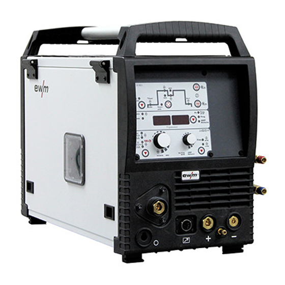
Page 16: Machine Description - Quick Overview
Machine description – quick overview Front view Machine description – quick overview Front view Figure 4-1 099-000237-EW501 25.04.2019... - Page 17 Machine description – quick overview Front view Item Symbol Description Transport bar Carrying handle Protective cap Cover for the wire feed mechanism and other operating elements. Depending on the machine series, additional stickers with information on the replace- ment parts and JOB lists will be located on the inside. Wire spool inspection window Check wire supply Slide latch, lock for the protective cap...
-
Page 18: Rear View
Machine description – quick overview Rear view Rear view Figure 4-2 099-000237-EW501 25.04.2019... - Page 19 Machine description – quick overview Machine control – Operating elements Item Symbol Description Connector plug, 5-pole Control lead Machine fuse (6,3 A) Main switch, machine on/off Connector plug (TIG) Welding current, minus potential Connecting nipple G¼, shielding gas connection Mains connection cable > see 5.1.7 chapter Cooling air inlet External wire feed inlet Pre-cut casing inlet for external wire feed.
-
Page 20: Machine Control - Operating Elements
Machine description – quick overview Machine control – Operating elements Machine control – Operating elements Unnamed operating elements have no function in this machine configuration! Figure 4-3 099-000237-EW501 25.04.2019... - Page 21 Machine description – quick overview Machine control – Operating elements Item Symbol Description Lid > see 4.3.1 chapter Push-button for switching the wire feed speed display m/min Wire feed speed in meters per minute. Wire feed speed in inch per minute. Display, left Wire feed speed Rotary dial, welding parameter setting...
-
Page 22: Machine Control - Concealed Operating Elements
Machine description – quick overview Machine control – Operating elements Machine control – Concealed operating elements 4.3.1 Figure 4-4 Item Symbol Description Select welding parameters button This button is used to select the welding parameters depending on the welding process and operating mode used. -
Page 23: Operating Elements In The Machine
Machine description – quick overview Machine control – Operating elements 4.3.2 Operating elements in the machine Figure 4-5 Item Symbol Description Wire spool holder Wire feed unit 099-000237-EW501 25.04.2019... -
Page 24: Connection Plan
Machine description – quick overview Connection plan Connection plan TIG 450W CW 12POL tigSpeed drive 45 coldwire Tetrix Figure 4-6 099-000237-EW501 25.04.2019... -
Page 25: Legend
Machine description – quick overview Connection plan 4.4.1 Legend Shielding gas Welding current (minus potential) Welding current (plus potential, workpiece) Coolant inlet (colour-coded) Coolant outlet (colour-coded) Hose package (HP = hose package) Control cable, cold wire (5-pole signal input) Control cable, cold wire (5-pole signal input) Supply voltage connection (1-phase) Supply voltage connection (3-phase) Welding torch control cable connection (12-pole) -
Page 26: Design And Function
Design and function Transport and installation Design and function WARNING Risk of injury from electrical voltage! Contact with live parts, e.g. power connections, can be fatal! • Observe the safety information on the first pages of the operating instructions! • Commissioning must be carried out by persons who are specifically trained in handling power sources! •... -
Page 27: Ambient Conditions
Design and function Transport and installation 5.1.2 Ambient conditions T he machine must not be operated in the open air and must only be set up and operated on a suitable, stable and level base! • The operator must ensure that the ground is non-slip and level, and provide sufficient lighting for the place of work. -
Page 28: Notes On The Installation Of Welding Current Leads
Design and function Transport and installation 5.1.5 Notes on the installation of welding current leads • Incorrectly installed welding current leads can cause faults in the arc (flickering). • Lay the workpiece lead and hose package of power sources without HF igniter (MIG/MAG) for as long and as close as possible in parallel. -
Page 29: Stray Welding Currents
Design and function Transport and installation 5.1.6 Stray welding currents WARNING Risk of injury due to stray welding currents! Stray welding currents can destroy protective earth conductors, damage machines and electronic devices and cause overheating of components, leading to fire. •... -
Page 30: Mains Connection
Design and function Transport and installation 5.1.7 Mains connection DANGER Hazards caused by improper mains connection! An improper mains connection can cause injuries or damage property! • The connection (mains plug or cable), the repair or voltage adjustment of the device must be carried out by a qualified electrician in accordance with the respective local laws or nati- onal regulations! •... -
Page 31: Permitted Torch Coolant
All information relates to the total hose package length of the complete welding system and presents exemplary configurations (of components of the EWM product portfolio with standard lengths). A straight kink-free installation is to be ensured, taking into account the max. delivery height. -
Page 32: Intermediate Hose Package Connection
Design and function Transport and installation 5.1.9 Intermediate hose package connection Property damage due to strain relief not installed or not installed correctly! The strain relief absorbs tensile forces on cables, plugs and sockets. If strain reliefs are not installed or not installed correctly, the connector plugs or sockets may be damaged. -
Page 33: Intermediate Hose Package Strain Relief
Design and function Transport and installation 5.1.9.1 Intermediate hose package strain relief The available attachment points of the intermediate hose package depend on the corresponding system configuration. Depending on the system configuration, suitable options for retrofitting (ON) are available. Figure 5-8 Item Symbol Description ON SR... -
Page 34: Locking The Strain Relief
Design and function Transport and installation 5.1.9.2 Locking the strain relief EWM intermediate hose package Figure 5-9 5.1.9.3 Control cable pin configuration Figure 5-10 Output (make contact) for torch trigger input of the power source (floating contact) 099-000237-EW501 25.04.2019... -
Page 35: Welding Torch Connection
Design and function Transport and installation 5.1.10 Welding torch connection Equipment damage due to improperly connected coolant pipes! If the coolant pipes are not properly connected or a gas-cooled welding torch is used, the coolant circuit is interrupted and equipment damage can occur. •... -
Page 36: Control Cable Pin Configuration
Design and function Transport and installation • Push the cable plug for the welding current (TIG) into the connector socket (TIG) and lock by turning to the right. • Insert shielding gas rapid-action closure nipple in the quick connect coupling and engage. •... -
Page 37: Wire Feed
Design and function Transport and installation 5.1.11 Wire feed CAUTION Risk of injury due to moving parts! The wire feeders are equipped with moving parts, which can trap hands, hair, clothing or tools and thus injure persons! • Do not reach into rotating or moving parts or drive components! •... -
Page 38: Changing The Wire Feed Rollers
Design and function Transport and installation 5.1.11.2 Changing the wire feed rollers Poor welding results due to faulty wire feeding! Wire feed rolls must be suitable for the diameter of the wire and the material. • Check the label of the rolls whether they fit the wire diameter. If necessary, turn or change! •... -
Page 39: Spool Brake Setting
Design and function Transport and installation Figure 5-15 Item Symbol Description Adjusting nut Feed roll tensioner Fixing the clamping unit and setting the pressure. Clamping unit Knurled screw Drive roller Guide tube Wire feed nipple Pressure roller • Extend and lay out the torch hose package. •... -
Page 40: Shielding Gas Supply (Shielding Gas Cylinder For Welding Machine)
Design and function Transport and installation • Tighten the Allen screw (8 mm) in the clockwise direction to increase the braking effect. Tighten the spool brake until the wire spool no longer turns when the wire feed motor stops but without it jamming during operation! 5.1.12 Shielding gas supply (shielding gas cylinder for welding machine) 5.1.12.1 Connecting the shielding gas supply... -
Page 41: Shielding Gas Volume Settings
Design and function Transport and installation Figure 5-17 Item Symbol Description Pressure regulator Shielding gas cylinder Output side of the pressure regulator Cylinder valve • Place the shielding gas cylinder into the relevant cylinder bracket. • Secure the shielding gas cylinder using a securing chain. •... -
Page 42: Gas Test
Design and function Transport and installation 5.1.13.1 Gas test Figure 5-18 5.1.13.2 Purge hose package 300s Figure 5-19 5.1.14 Configuring the welding machine for mechanical arc fusion welding Before the welding machine is commissioned it has to be configured for mechanical arc fusion welding. The basic settings are configured directly at the welding machine control. -
Page 43: Selection And Adjustment
Design and function Transport and installation 5.1.15 Selection and adjustment To set the welding programs, you can use the machine control. The left hand display shows the wire feed speed, the right hand display shows further parameter settings such as program number or hot wire cur- rent (for hotwire only). -
Page 44: Superpuls
Design and function Transport and installation 5.1.15.1 superPuls The EWM superPuls function enables automatic switching between two operating points in a process. ENTER EXIT Figure 5-21 Display Setting/selection Selects superPuls Switches function on or off. Switch on Switching on machine function... -
Page 45: Operating Modes (Functional Sequences)
Design and function Transport and installation 5.1.16 Operating modes (functional sequences) Torch trigger 1 (BRT 1) switches the welding current on or off. Torch trigger 2 (BRT 2) switches the wire feeding on or off. In addition, you can inch the wire by pressing torch trigger 2 (BRT 2) or reverse inch the wire by tapping You can choose between four operating modes (see the following functional sequences). -
Page 46: Non-Latched Manual
Design and function Transport and installation 5.1.16.2 Non-latched Manual The welding machine (power source) must be set to operating mode “latched”. Figure 5-23 First cycle (current) • Press torch trigger 1 (BRT 1), the gas pre-flow time elapses. • HF ignition pulses jump from the tungsten electrode to the workpiece. The arc ignites. •... -
Page 47: Latched Manual
Design and function Transport and installation 5.1.16.3 Latched manual Figure 5-24 This operating mode differs from non-latched operation in the following ways: • Wire feeding is started by pressing and releasing (tapping) BRT 2. • By tapping you can switch to the reduced wire feeding. •... -
Page 48: Non-Latched Automatic
Design and function Transport and installation 5.1.16.4 Non-latched automatic The welding machine (power source) must be set to operating mode “non-latched”. Figure 5-25 First cycle (current) • Press torch trigger 1 (BRT 1) and keep pressed. • The gas pre-flow time elapses. •... -
Page 49: Latched Automatic
Design and function Transport and installation 5.1.16.5 Latched automatic The welding machine (power source) must be set to operating mode “latched”. Figure 5-26 1. cycle (current) • Press torch trigger 1 (BRT 1), the gas pre-flow time elapses. • HF ignition pulses jump from the tungsten electrode to the workpiece. The arc ignites. •... -
Page 50: Tack Welding
Design and function Transport and installation 5.1.16.6 Tack welding The welding machine (power source) must be set to operating mode “non-latched”. Figure 5-27 Sequence: • Press torch trigger 1 (BRT 1) and keep pressed. • The gas pre-flow time elapses. •... -
Page 51: Menus And Sub-Menus On The Machine Control
Design and function Menus and sub-menus on the machine control Menus and sub-menus on the machine control 5.2.1 Direct menus (direct access to parameters) Functions, parameters and their values can be accessed directly, e.g. can be selected by pressing a but- ton once. -
Page 52: Welding Torch Holder
Design and function Welding torch holder Welding torch holder The item described in the following is part of the machine´s scope of delivery. Figure 5-29 Item Symbol Description Crossmember of the transport handle Torch holder Fixing screws (x 4) Fan-type lock washers •... -
Page 53: Maintenance, Care And Disposal
Maintenance, care and disposal General Maintenance, care and disposal General DANGER Risk of injury due to electrical voltage after switching off! Working on an open machine can lead to fatal injuries! Capacitors are loaded with electrical voltage during operation. Voltage remains present for up to four minutes after the mains plug is removed. -
Page 54: Maintenance Work, Intervals
A periodic test according to IEC 60974-4 "Periodic inspection and test" has to be carried out. In addition to the regulations on testing given here, the relevant local laws and regulations must also be observed. For more information refer to the "Warranty registration" brochure supplied and our information regarding warranty, maintenance and testing at www.ewm-group.com! 099-000237-EW501 25.04.2019... -
Page 55: Disposing Of Equipment
• Information about returning used equipment or about collections can be obtained from the respective municipal administration office. • In addition to this, returns are also possible throughout Europe via EWM sales partners. 099-000237-EW501 25.04.2019... -
Page 56: Rectifying Faults
Rectifying faults Checklist for rectifying faults Rectifying faults All products are subject to rigorous production checks and final checks. If, despite this, something fails to work at any time, please check the product using the following flowchart. If none of the fault rectification procedures described leads to the correct functioning of the product, please inform your authorised dea- ler. -
Page 57: Error Messages
Rectifying faults Error messages Wire feed problems Unsuitable or worn welding torch equipment Adjust contact tip (cold wire/hot wire) to wire diameter, blow through and replace if necessary Adjust wire guide to material in use, blow through and replace if necessary ... -
Page 58: Resetting Welding Parameters To The Factory Settings
Rectifying faults Resetting welding parameters to the factory settings Resetting welding parameters to the factory settings All customised welding parameters that are stored will be replaced by the factory settings. Figure 7-1 099-000237-EW501 25.04.2019... -
Page 59: Vent Coolant Circuit
Rectifying faults Vent coolant circuit Vent coolant circuit To vent the cooling system always use the blue coolant connection, which is located as deep as possible inside the system (close to the coolant tank)! Figure 7-2 Complete the following steps to vent the welding torch: •... -
Page 60: Technical Data
Technical data tigSpeed continuous drive 45 coldwire Technical data tigSpeed continuous drive 45 coldwire Performance specifications and guarantee only in connection with original spare and replacement parts! Mains voltage (Tolerance) 1 x 230 V (-40 % to +15 %) Frequency... -
Page 61: Accessories
Accessories Options Accessories Performance-dependent accessories like torches, workpiece leads, electrode holders or intermediate hose packages are available from your authorised dealer. Options Type Designation Item no. ON WAK tigSpeed Wheel assembly kit with strain relief 092-007927-00000 ON Filter TG.0003 Dirt filter 092-002662-00000 ON AS SR tigSpeed Strain relief... -
Page 62: Replaceable Parts
Replaceable parts Wire feed rollers Replaceable parts Performance specifications and guarantee only in connection with original spare and replacement parts! 10.1 Wire feed rollers 10.1.1 Wire feed rollers for steel wire Type Designation Item no. FE 2DR4R 0,6+0,8 Drive rollers, 37 mm, steel 092-000839-00000 FE 2DR4R 0,8+1,0 Drive rollers, 37 mm, steel... -
Page 63: Appendix
Appendix Setting instructions Appendix 11.1 Setting instructions The following lists help you to determine the parameters. The actual parameters to be set depend on the joint and welding position. The welding speed as well depends on the welding task and the parameters set. Figure 11-1 Item Description... -
Page 64: Continuous Tig Cold Wire Welding
Appendix Setting instructions 11.1.1 Continuous TIG cold wire welding Fillet weld PB position Parent metal: Unalloyed/low-alloy Welding consumable: Unalloyed/low-alloy, Ø 1.0 mm t [mm] Is [A] Hz [1/s] IH [A] Vs [cm/min] Welding torch Wire angle [°] (m/min) [°] Forehand 10– 41-42 Forehand 10–... -
Page 65: Superpuls Tig Cold Wire Welding
Appendix Setting instructions 11.1.2 superPuls TIG cold wire welding Fillet weld PB position Parent metal: Unalloyed/low-alloy Welding consumable: Unalloyed/low-alloy, Ø 1.0 mm Wf1/tWF1 Wf2/tWF2 Welding Wire angle torch [mm] [m/min] [sec] [m/min] [sec] [cm/min] [°] [°] 0.15 0.0/off 0.35 Forehand 15 0.15 0.0/off 0.35... -
Page 66: Superpuls Tig Cold Wire Welding
Appendix Setting instructions Fillet weld PF position Parent metal: High-alloy Welding consumable: High-alloy. Ø 1.0 mm t [mm] Is [A] Hz [1/s] IH [A] Vs [cm/min] Welding torch Wire angle [°] (m/min) [°] Forehand 10– 41-42 Forehand 10– 41-42 Forehand 10– 41-42 Forehand 10–... -
Page 67: Searching For A Dealer
Appendix Searching for a dealer 11.2 Searching for a dealer Sales & service partners www.ewm-group.com/en/specialist-dealers "More than 400 EWM sales partners worldwide" 099-000237-EW501 25.04.2019...
Need help?
Do you have a question about the tigSpeed continuous drive 45 coldwire and is the answer not in the manual?
Questions and answers