
Related Manuals for EWM Tetrix drive 4L


Summary of Contents for EWM Tetrix drive 4L
- Page 1 Operating instructions Wire feed unit Tetrix drive 4L 099-000094-EW501 Observe additional system documents! 18.07.2017...
- Page 2 +49 2680 181-0. A list of authorised sales partners can be found at www.ewm-group.com. Liability relating to the operation of this equipment is restricted solely to the function of the equipment.
-
Page 3: Table Of Contents
Contents Notes on the use of these operating instructions Contents 1 Contents ..............................3 2 For your safety ............................5 Notes on the use of these operating instructions ................5 Explanation of icons ........................6 Part of the complete documentation ....................7 3 Intended use ............................ - Page 4 Contents Notes on the use of these operating instructions 8 Technical data ............................31 Tetrix drive 4L ..........................31 9 Accessories ............................32 General accessories ........................32 Options ............................32 Remote control / connection cable ....................32 10 Replaceable parts ..........................33 10.1 Wire feed rollers ...........................
-
Page 5: For Your Safety
For your safety Notes on the use of these operating instructions For your safety Notes on the use of these operating instructions DANGER Working or operating procedures which must be closely observed to prevent imminent serious and even fatal injuries. •... -
Page 6: Explanation Of Icons
For your safety Explanation of icons Explanation of icons Symbol Description Symbol Description Indicates technical aspects which the Activate and release/tap/tip user must observe. Switch off machine Release Switch on machine Press and keep pressed Switch Wrong Turn Numerical value – adjustable Correct Menu entry Signal light lights up in green... -
Page 7: Part Of The Complete Documentation
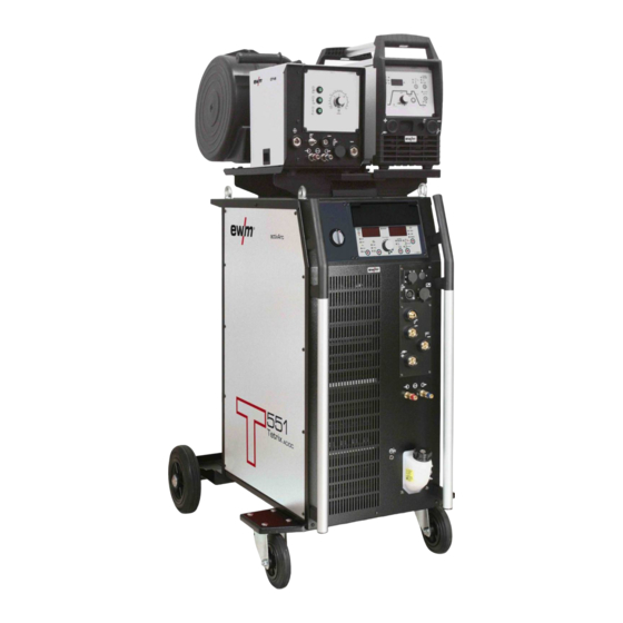
For your safety Part of the complete documentation Part of the complete documentation These operating instructions are part of the complete documentation and valid only in combination with all other parts of these instructions! Read and observe the operating instructions for all system components, especially the safety instructions! The illustration shows a general example of a welding system. -
Page 8: Intended Use
In case of unauthorised changes, improper repairs, non-compliance with specified deadlines for "Arc Welding Equipment – Inspection and Testing during Operation", and/or prohibited modifications which have not been explicitly authorised by EWM, this declaration shall be voided. An original document of the specific declaration of conformity is included with every product. -
Page 9: Machine Description - Quick Overview
Machine description – quick overview Front view Machine description – quick overview Front view Figure 4-1 Item Symbol Description Carrying handle Slide latch, lock for the protective cap Wire electrode connection Welding torch wire feed Quick connect coupling (red) coolant return Quick connect coupling (blue) coolant supply Connection socket, welding torch control cable >... -
Page 10: Rear View
Machine description – quick overview Rear view Rear view Figure 4-2 Item Symbol Description Connection socket, 19-pole Remote control connection Connector plug (TIG hot wire) Welding current, minus potential Connecting thread (G¼") Shielding gas Connection socket (28-pole) Control lead Connector plug (TIG) Welding current, minus potential Machine feet Intermediate hose package strain relief... -
Page 11: Inside View
Machine description – quick overview Inside view Inside view Figure 4-3 Item Symbol Description Cover of the wire spool Wire spool holder Protective cap Cover for the wire feed mechanism and other operating elements. Depending on the machine series, additional stickers with information on the replacement parts will be located on the inside. -
Page 12: Machine Control - Operating Elements
Machine description – quick overview Machine control – Operating elements Machine control – Operating elements Figure 4-4 Item Symbol Description Gas test button Shielding gas setting/tube package Rinse. (See the operating instructions for the power source, chapter “Gas test”) Wire inching button To inch the wire electrode when changing wire spools Wire return button The welding wire is retracted to the wire spool. -
Page 13: Design And Function
Design and function Ambient conditions Design and function WARNING Risk of injury from electric shock! Contact with live parts, e.g. welding current sockets, is potentially fatal! • Follow safety instructions on the opening pages of the operating instructions. • Commissioning may only be carried out by persons who have the relevant expertise of working with arc welding machines! •... -
Page 14: Connection Plan
Design and function Transport and installation 5.2.1 Connection plan 5.2.1.1 TIG hot wire welding Tetrix drive 4L TIG 450W HW 12POL hotwire Tetrix Hotwire RT AW 1 hotwire Tetrix AW Figure 5-1 099-000094-EW501 18.07.2017... -
Page 15: Tig Cold Wire Welding
Design and function Transport and installation 5.2.1.2 TIG cold wire welding Tetrix drive 4L TIG 450 WD CW RT AW 1 hotwire Tetrix AW Figure 5-2 5.2.1.3 Legend Shielding gas Welding current(minus potential) Coolant input (marked in colour) 099-000094-EW501 18.07.2017... -
Page 16: Welding Torch Cooling System
Design and function Transport and installation Coolant output (marked in colour) Control lead (28-pole) Hose package (TP = tube package) Welding current (minus potential, TIG hot wire) Welding current (plus potential, workpiece) Control lead, hot wire (signal input, 4-pole) hotwire Connection, supply voltage (3-phase) Supply voltage, hot wire power source Control lead, hot wire (signal output, 4-pole) -
Page 17: Maximal Hose Package Length
Design and function Transport and installation 5.2.2.2 Maximal hose package length Pump 3.5 bar Pump 4.5 bar Machines with or without separate wire feeder 30 m 60 m Compact machines with additional intermediate 20 m 30 m drive (example. miniDrive) Machines with separate wire feeder and additional 20 m 60 m... -
Page 18: Stray Welding Currents
Design and function Transport and installation Always keep leads as short as possible! Lay any excess cable lengths in meanders. Figure 5-5 5.2.3.1 Stray welding currents WARNING Risk of injury due to stray welding currents! Stray welding currents can destroy protective earth conductors, damage machines and electronic devices and cause overheating of components, leading to fire. -
Page 19: Intermediate Hose Package Connection
Design and function Transport and installation 5.2.4 Intermediate hose package connection Figure 5-7 Item Symbol Description Power source Intermediate hose package Quick connect coupling (blue) coolant supply Connector plug (TIG hot wire) Welding current, minus potential Connecting thread (G¼") Shielding gas Connection socket (28-pole) Control lead Connector plug (TIG) -
Page 20: Connecting The Shielding Gas Supply
Design and function Transport and installation 5.2.4.1 Connecting the shielding gas supply WARNING Risk of injury due to improper handling of shielding gas cylinders! Improper handling and insufficient securing of shielding gas cylinders can cause serious injuries! • Place shielding gas cylinder into the designated holder and secure with fastening elements (chain/belt)! •... -
Page 21: Control Cable Pin Configuration
Design and function Transport and installation Item Symbol Description Welding torch hose package Wire electrode connection Welding torch wire feed Quick connect coupling Shielding gas Connection socket (TIG hot wire) Hot wire power, minus potential Connection socket, welding torch control cable > see 5.2.5.1 chapter Connection socket (TIG) Welding current, minus potential Quick connect coupling (blue) -
Page 22: Wire Feed
Design and function Wire feed Wire feed CAUTION Risk of injury due to moving parts! The wire feeders are equipped with moving parts, which can trap hands, hair, clothing or tools and thus injure persons! • Do not reach into rotating or moving parts or drive components! •... -
Page 23: Changing The Wire Feed Rollers
Design and function Wire feed 5.3.1.2 Changing the wire feed rollers Unsatisfactory welding results due to faulty wire feeding! Wire feed rollers must be suitable for the diameter of the wire and the material. • Check the roller label to verify that the rollers are suitable for the wire diameter. Turn or change if necessary! •... -
Page 24: Spool Brake Setting
Design and function Remote control Item Symbol Description Feed roll tensioner Fixing the clamping unit and setting the pressure. Clamping unit Knurled screw Pressure roller Drive roller Wire feed nipple Guide tube • Extend and lay out the torch hose package. •... - Page 25 Design and function Remote control Figure 5-14 Item Symbol Description 19-pole connection socket (analogue) For connecting the control lead. Wire inching button Inching the wire electrode when changing the wire spool. (The welding wire is inched loosely into the hose package, without gas being expelled.) Wire return button The welding wire is retracted to the wire spool.
-
Page 26: Maintenance, Care And Disposal
Maintenance, care and disposal General Maintenance, care and disposal General DANGER Risk of injury due to electrical voltage after switching off! Working on an open machine can lead to fatal injuries! Capacitors are loaded with electrical voltage during operation. Voltage remains present for up to four minutes after the mains plug is removed. -
Page 27: Maintenance Work, Intervals
A periodic test according to IEC 60974-4 "Periodic inspection and test" has to be carried out. In addition to the regulations on testing given here, the relevant local laws and regulations must also be observed. For more information refer to the "Warranty registration" brochure supplied and our information regarding warranty, maintenance and testing at www.ewm-group.com! 099-000094-EW501 18.07.2017... -
Page 28: Disposing Of Equipment
In addition to this, returns are also possible throughout Europe via EWM sales partners. Meeting the requirements of RoHS We, EWM AG in Mündersbach, Germany, hereby confirm that all products which we supply to you and that are subject to the RoHS directive comply with RoHS requirements (also see applicable EC directives on the Declaration of Conformity on your machine). -
Page 29: Rectifying Faults
Rectifying faults Checklist for rectifying faults Rectifying faults All products are subject to rigorous production checks and final checks. If, despite this, something fails to work at any time, please check the product using the following flowchart. If none of the fault rectification procedures described leads to the correct functioning of the product, please inform your authorised dealer. - Page 30 Rectifying faults Checklist for rectifying faults Wire feed problems Unsuitable or worn welding torch equipment Adjust contact tip (cold wire/hot wire) to wire diameter, blow through and replace if necessary Adjust wire guide to material in use, blow through and replace if necessary ...
-
Page 31: Technical Data
Technical data Tetrix drive 4L Technical data Performance specifications and guarantee only in connection with original spare and replacement parts! Tetrix drive 4L Supply voltage 42 VAC/60 VDC Max. welding current at 60% DC 550 A Max. welding current at 100% DC... -
Page 32: Accessories
Tube bridge 092-007843-00000 Options Type Designation Item no. ON TB drive 4L/HW Transport bracket for Tetrix drive 4L and Tetrix 270 092-000038-00000 Hotwire ON PS drive 4L T/P Pivot support 092-002112-00000 ON WAKD2 4L/41L Optional wheel assembly retrofit kit for drive 4L... -
Page 33: Replaceable Parts
Replaceable parts Wire feed rollers Replaceable parts The manufacturer's warranty becomes void if non-genuine parts are used! • Only use system components and options (power sources, welding torches, electrode holders, remote controls, spare parts and replacement parts, etc.) from our range of products! •... - Page 34 Replaceable parts Wire feed rollers Figure 10-1 099-000094-EW501 18.07.2017...
-
Page 35: Overview Of Ewm Branches
Appendix A Overview of EWM branches Appendix A 11.1 Overview of EWM branches 099-000094-EW501 18.07.2017...
Need help?
Do you have a question about the Tetrix drive 4L and is the answer not in the manual?
Questions and answers