Sign In
Upload
Download
Table of Contents
Contents
Add to my manuals
Delete from my manuals
Share
URL of this page:
HTML Link:
Bookmark this page
Add
Manual will be automatically added to "My Manuals"
Print this page
×
Bookmark added
×
Added to my manuals
Manuals
Brands
EWM Manuals
Welding Accessories
cool40 U31
Operating instructions manual
EWM cool40 U31 Operating Instructions Manual
Air-cooling units for water-cooled welding torches
Hide thumbs
1
2
Table Of Contents
3
4
5
6
7
8
9
10
11
12
13
14
15
16
17
18
19
20
21
22
23
page
of
23
Go
/
23
Contents
Table of Contents
Bookmarks
Table of Contents
1 Contents
Table of Contents
2 For Your Safety
Notes on the Use of These Operating Instructions
Explanation of Icons
Part of the Complete Documentation
3 Intended Use
Applications
For Operation Only with the Following Equipment
Cool 40 U31
Cool41 U31
Documents Which also Apply
Warranty
Declaration of Conformity
Service Documents (Spare Parts and Circuit Diagrams)
4 Machine Description - Quick Overview
Front View
Rear View
5 Design and Function
Assembly/Disassembly
Connecting the Supply Lines
Transport and Installation
Machine Cooling
Ambient Conditions
In Operation
Transport and Storage
Welding Torch Cooling System
Functional Characteristics
Permitted Torch Coolant
Maximal Hose Package Length
Adding Coolant
Welding Torch Connection
6 Maintenance, Care and Disposal
General
Cleaning
Dirt Filter
Maintenance Work, Intervals
Daily Maintenance Tasks
Monthly Maintenance Tasks
Annual Test (Inspection and Testing During Operation)
Disposing of Equipment
7 Rectifying Faults
Checklist for Rectifying Faults
Vent Coolant Circuit
Fixing the Pump Shaft (Coolant Circuit)
8 Technical Data
Cool40 U31; Cool41 U31
9 Accessories
General Accessories
10 Appendix
Searching for a Dealer
Advertisement
Quick Links
1
Cool 40 U31
2
Service Documents (Spare Parts and Circuit Diagrams)
3
Fixing the Pump Shaft (Coolant Circuit)
4
Cool40 U31; Cool41 U31
Download this manual
Operating instructions
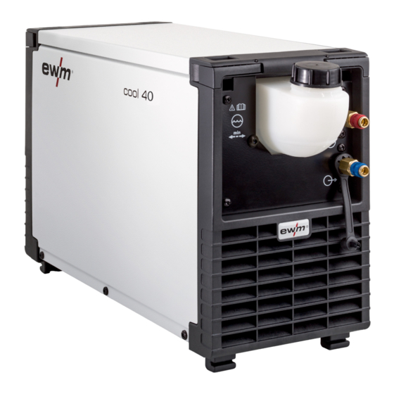
Air-cooling units for water-cooled welding torches
EN
cool40 U31
cool41 U31
099-008593-EW501
Observe additional system documents!
26.07.2019
Table of
Contents
Previous
Page
Next
Page
1
2
3
4
5
Advertisement
Table of Contents
Need help?
Do you have a question about the cool40 U31 and is the answer not in the manual?
Ask a question
Questions and answers
Related Manuals for EWM cool40 U31
Welding Accessories EWM cool50 U42 Operating Instructions Manual
Air-cooling units for water-cooled welding torches (29 pages)
Welding Accessories EWM cool41 U31 Operating Instructions Manual
Air-cooling units for water-cooled welding torches (23 pages)
Welding Accessories EWM TROLLY 31-2/35-2 Operating Instructions Manual
Transport vehicle (12 pages)
Welding Accessories EWM BUSINT X11 Operating Instructions Manual
Interface for digital welding power sources (134 pages)
Welding Accessories EWM tigSpeed continuous drive 45 hotwire Operating Instructions Manual
Wire feed unit (73 pages)
Welding Accessories EWM PM451 W F1 Operating Instructions Manual
Welding torch (76 pages)
Welding Accessories EWM Basic XQ Operating Instructions Manual
Control (55 pages)
Welding Accessories EWM UM 24 G EZA Quick Start Manual
Welding torch (12 pages)
Welding Accessories EWM Trolly 55-5 Operating Instructions Manual
Transport systems (23 pages)
Welding Accessories EWM tigSpeed continuous drive 45 coldwire Operating Instructions Manual
Wire feed unit (67 pages)
Welding Accessories EWM TIG-SR 300 GD HD Operating Instructions Manual
Welding torch (30 pages)
Welding Accessories EWM TH AMT Operating Instructions Manual
Torch holder (23 pages)
Welding Accessories EWM Tetrix drive 4L Operating Instructions Manual
Wire feed unit (35 pages)
Welding Accessories EWM miniDrive GS Operating Instructions Manual
Intermediate drive unit (35 pages)
Welding Accessories EWM TIG 17 G Operating Instructions Manual
Welding torch (22 pages)
Welding Accessories EWM PHB 50 20 A Operating Instructions Manual
Welding torch (25 pages)
This manual is also suitable for:
Cool41 u31
Table of Contents
Print
Rename the bookmark
Delete bookmark?
Delete from my manuals?
Login
Sign In
OR
Sign in with Facebook
Sign in with Google
Upload manual
Upload from disk
Upload from URL


Need help?
Do you have a question about the cool40 U31 and is the answer not in the manual?
Questions and answers