EWM Basic XQ Operating Instructions Manual
Control
Hide thumbs
Also See for Basic XQ:
- Operating instructions manual (49 pages) ,
- Operating instructions manual (56 pages) ,
- Operating instructions manual (59 pages)

Related Manuals for EWM Basic XQ


Summary of Contents for EWM Basic XQ
- Page 1 Operating instructions Control Basic XQ (M3.7X-S, M3.7X-T) 099-0M37XS-EW501 Observe additional system documents! 31.8.2022...
- Page 2 +49 2680 181-0. A list of authorised sales partners can be found at www.ewm-group.com/en/specialist-dealers. Liability relating to the operation of this equipment is restricted solely to the function of the equipment. No other f orm of liability, regardless of type, shall be accepted.
-
Page 3: Table Of Contents
Contents Notes on using these operating instructions Contents 1 Contents........................3 2 For your safety......................5 Notes on using these operating instructions ............... 5 Explanation of icons ....................6 Saf ety instructions ....................7 Transport and installation ..................10 3 Intended use ........................12 Use and operation solely with the following machines ..........12 Software version ....................12 Documents which also apply ...................12... - Page 4 Contents Notes on using these operating instructions 5.7.3 Operating modes (f unctional sequences).............34 5.7.3.1 Explanation of signs and functions ..........34 5.7.3.2 Automatic cut-out ...............34 Special parameters (advanced settings) ..............36 5.8.1 Selecting, changing and saving parameters ..........36 5.8.2 Ramp time for wire inching (P1) ..............37 5.8.3 Latched/special-latched tap start (P9) ............37 5.8.4...
-
Page 5: For Your Safety
For your safety Notes on using these operating instructions For your safety Notes on using these operating instructions DANGER Working or operating procedures which must be closely observed to prevent imminent serious and even fatal injuries. • Saf ety notes include the "DANGER" keyword in the heading with a general warning symbol. •... -
Page 6: Explanation Of Icons
For your safety Explanation of icons Explanation of icons Symbol Description Symbol Description Indicates technical aspects which the Activate and release / Tap / Tip user must observe. Switch off machine Release Switch on machine Press and hold Incorrect / Invalid Switch Correct / Valid Turn... -
Page 7: Safety Instructions
For your safety Saf ety instructions Safety instructions WARNING Risk of accidents due to non-compliance with the safety instructions! Non-compliance with the safety instructions can be fatal! • Caref ully read the safety instructions in this manual! • Observe the accident prevention regulations and any regional regulations! •... - Page 8 For your safety Saf ety instructions WARNING Risk of injury due to improper clothing! During arc welding, radiation, heat and voltage are sources of risk that cannot be avoided. The user has to be equipped with the complete personal protective equipment at all times.
- Page 9 For your safety Saf ety instructions CAUTION Smoke and gases! Smoke and gases can lead to breathing difficulties and poisoning. In addition, solvent vapour (chlorinated hydrocarbon) may be converted into poisonous phosgene due to the ultraviolet radiation of the arc! •...
-
Page 10: Transport And Installation
For your safety Transport and installation CAUTION Obligations of the operator! The respective national directives and laws must be complied with when operating the machine! • Implementation of national legislation relating to framework directive 89/391/EEC on the int- roduction of measures to encourage improvements in the safety and health of workers at work and associated individual guidelines. - Page 11 For your safety Transport and installation CAUTION Risk of accidents due to supply lines! During transport, attached supply lines (mains leads, control cables, etc.) can cause risks, e.g. by causing connected machines to tip over and injure persons! • Disconnect all supply lines before transport! Risk of tipping! There is a risk of the machine tipping over and injuring persons or being damaged itself during movement and set up.
-
Page 12: Intended Use
Intended use Use and operation solely with the following machines Intended use WARNING Hazards due to improper usage! The machine has been constructed to the state of the art and any regulations and stand- ards applicable for use in industry and trade. It may only be used for the welding proce- dures indicated at the rating plate. -
Page 13: Part Of The Complete Documentation
Intended use Documents which also apply 3.3.1 Part of the complete documentation This document is part of the complete documentation and valid only in combination with all other parts of these instructions! Read and observe the operating instructions for all system components, especially the safety instructions! The illustration shows a general example of a welding system. -
Page 14: Machine Control - Operating Elements
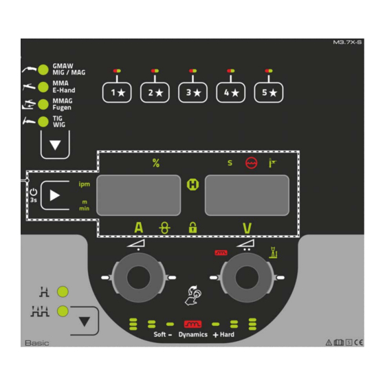
Machine control – Operating elements Overview of control sections Machine control – Operating elements Overview of control sections For description purposes, the machine control has been divided into two sections (A, B) to ensure maximum clarity. The setting ranges for the parameter values are summarised in the parameter overview section >... -
Page 15: Control Section A
Machine control – Operating elements Overview of control sections 4.1.1 Control section A Figure 4-2 099-0M37XS-EW501 31.8.2022... - Page 16 Machine control – Operating elements Overview of control sections Item Symbol Description Push-button for welding procedure ------ MIG/MAG welding ------- MMA welding ------ Gouging ------- TIG welding Click wheel wire feed speed / welding current • ----------- Setting the wire feed speed / welding current > see 4.2.2 chapter •...
-
Page 17: Control Section B
Machine control – Operating elements Overview of control sections 4.1.2 Control section B Figure 4-3 Item Symbol Description Display left / Lock function push-button Switching the device display between various welding parameters. Signal lamps show the selected parameter. --------- Press f or 3 s to put the machine into lock function > see 4.2.4 chapter. Wire feed speed unit signal light m/min --- Parameter value is displayed in meters per minute. -
Page 18: Welding Data Display
Machine control – Operating elements Overview of control sections Item Symbol Description Signal light welding voltage Illuminates when the welding voltage is displayed in volts. Display, right > see 4.1.3 chapter V ---------- welding voltage Excess temperature signal light / Welding torch cooling failure For error messages >... -
Page 19: Operating The Machine Control
Machine control – Operating elements Operating the machine control Operating the machine control 4.2.1 Main screen The machine control switches to the main screen again and again after it has been turned on or a para- meter setting has been completed. This means that the previously selected settings (indicated by signal lights where applicable) are adopted and that the nominal value for the wire feed speed is shown in the lef t-hand welding data display. -
Page 20: Loading Saved Favourites
Machine control – Operating elements Operating the machine control 4.2.5.2 Loading saved Favourites Figure 4-7 • Press the f avourite memory push-button (the signal light of the favourite status is green). 4.2.5.3 Deleting saved Favourites Figure 4-8 • Press and hold the favourite memory push-button. Af ter 2 seconds, the signal light of the favourite status turns green af ter another 5 s, the signal light starts flashing red af ter another 5 s the signal light goes out... -
Page 21: Functional Characteristics
Functional characteristics Shielding gas volume settings Functional characteristics Shielding gas volume settings If the shielding gas setting is too low or too high, this can introduce air to the weld pool and may cause pores to form. Adjust the shielding gas quantity to suit the welding task! •... -
Page 22: Purge Hose Package
Functional characteristics Wire inching 5.1.2 Purge hose package The operating elements are installed under the protective cap of wire feed mechanism. 300s Figure 5-2 Wire inching The wire inching f unction is used for potential- and gas-free inching of the wire electrode after the wire spool change. -
Page 23: Wire Return
Functional characteristics Wire return Wire return The wire return f unction is used to retract the wire electrode without tension and protection gas. By simul- taneously pressing and holding the wire inching and gas test buttons, the wire return speed increases in a ramp f unction (special parameter P1 >... -
Page 24: Mig/Mag Welding
Functional characteristics MIG/MAG welding MIG/MAG welding 5.4.1 Welding task selection The f ollowing steps have to be carried out to select the welding job: • Select welding procedure. • Select operating mode. • Set welding power (wire f eed speed and welding voltage). •... -
Page 25: Welding Power (Operating Point)
Functional characteristics MIG/MAG welding 5.4.4 Welding power (operating point) This control uses the principle of twin-knob operation. To specify the operating point, only the wire f eed speed and the welding voltage are selected according to the type of material, shielding gas, material thickness, and wire diameter (see also table setting instructions in the Appendix >... -
Page 26: Arc Dynamics (Choke Effect)
Functional characteristics MIG/MAG welding 5.4.5 Arc dynamics (choke effect) This f unction can be used to adjust the arc between a narrow, hard arc with deep penetration (positive values) and a wide and soft arc (negative values). In addition, the selected settings are displayed with signal lights below the rotary knobs. -
Page 27: Burn-Back
Functional characteristics MIG/MAG welding Display Setting/selection Gas post-flow time Burn-back time > see 5.4.6.1 chapter • ----------- Increase value > increase wire burn-back • ----------- Decrease value > decrease wire burn-back Wire creep 5.4.6.1 Burn-back The wire burn-back parameter prevents the sticking of the wire electrode in the weld pool or at the contact tip at the end of the welding process. -
Page 28: Automatic Cut-Out
Functional characteristics MIG/MAG welding 5.4.7.2 Automatic cut-out Once the f ault periods have elapsed, the automatic cut-out stops the welding process when it has been triggered by one of two states: • During ignition 5 s af ter the start of the welding process, no welding current flows (ignition error). •... - Page 29 Functional characteristics MIG/MAG welding Latched mode Figure 5-11 Step 1 • Press and hold torch trigger • Shielding gas is expelled (gas pre-flows) • Wire f eed motor runs at “creep speed”. • Arc ignites after the wire electrode makes contact with the workpiece; welding current flows. •...
-
Page 30: Standard Mig/Mag Torch
Functional characteristics MMA welding 5.4.8 Standard MIG/MAG torch The MIG welding torch trigger is essentially used to start and stop the welding process. Operating elements Functions Torch trigger • Start/stop welding 5.4.8.1 Switching between Push/Pull and intermediate drive WARNING No improper repairs and modifications! To prevent injuries and damage to the machine, only competent personnel (authorised service personnel) are allowed to repair or modify the machine. -
Page 31: Welding Current Setting
Functional characteristics MMA welding 5.5.1.1 Welding current setting Figure 5-13 5.5.2 Arcforce Figure 5-14 Setting: • Negative values: rutile electrode types • Values at zero: basic electrode types • Positive values: cellulose electrode types 5.5.3 Hotstart The f unction hot start ensures a secure igniting of the arc and a sufficient heating to the still cold parent metal at the beginning of the welding process. -
Page 32: Air Arc Gouging
Functional characteristics Air arc gouging Air arc gouging 5.6.1 Welding task selection Figure 5-17 5.6.2 Welding current setting Figure 5-18 TIG welding 5.7.1 Welding task selection Figure 5-19 099-0M37XS-EW501 31.8.2022... -
Page 33: Welding Current Setting
Functional characteristics TIG welding 5.7.1.1 Welding current setting Figure 5-20 5.7.2 Arc ignition 5.7.2.1 Liftarc Figure 5-21 The arc ignites through contact with the workpiece: a) Caref ully place the torch gas nozzle and tungsten electrode tip against the workpiece (lift arc current f lows independent of the set main current) b) Angle the torch above the torch gas nozzle until the distance between electrode t ip and workpiece is approx. -
Page 34: Operating Modes (Functional Sequences)
Functional characteristics TIG welding 5.7.3 Operating modes (functional sequences) 5.7.3.1 Explanation of signs and functions Symbol Meaning Press torch trigger Release torch trigger Tap torch trigger (briefly press and release) Shielding gas is flowing Welding power Gas pre-f low Gas post-flow Non-latched Latched Time... - Page 35 Functional characteristics TIG welding Non-latched mode Figure 5-22 Selection • Select non-latched operating mode Step 1 • Press and hold torch trigger. • Shielding gas is expelled (gas pre-flows). The arc is ignited using liftarc. • Welding current flows with pre-selected setting. Step 2 •...
-
Page 36: Special Parameters (Advanced Settings)
Functional characteristics Special parameters (advanced settings) Special parameters (advanced settings) Special parameters (P1 to Pn) are applied for customer-specific configuration of machine functions. This allows the user maximum flexibility in optimising their requirements. These settings are not configured directly on the machine control since a regular setting of the parame- ters is generally not required. -
Page 37: Ramp Time For Wire Inching (P1)
Functional characteristics Special parameters (advanced settings) Display Setting/selection Correction or nominal voltage display 0 = -------- Correction voltage display (ex works). 1 = -------- Absolute nominal voltage display. Unit system > see 5.8.6 chapter 0 = -------- metric system (ex works) 1 = -------- Imperial system 5.8.2 Ramp time for wire inching (P1) -
Page 38: Machine Configuration Menu
Functional characteristics Machine configuration menu Machine configuration menu 5.9.1 Selecting, changing and saving parameters Figure 5-26 Display Setting/selection Lead resistance 1 Lead resistance for the first welding circuit 0 mΩ–60 mΩ (8 mΩ ex works). Lead resistance 2 Lead resistance for the second welding circuit 0 mΩ–60 mΩ (8 mΩ ex works). Only qualified service personnel may change the parameters! Only qualified service personnel may change the parameters! 099-0M37XS-EW501... -
Page 39: Aligning The Cable Resistance
Functional characteristics Machine configuration menu Display Setting/selection Time-based power-saving mode > see 5.10 chapter Time to activation of the power-saving mode in case of inactivity. Setting = disabled or numerical value 5-60 min.. Service menu Modifications to the service menu may only be carried out by authorised maintenance staf f! 5.9.2 Aligning the cable resistance... -
Page 40: Power-Saving Mode (Standby)
Functional characteristics Power-saving mode (Standby) 1 Preparation • Switch off the welding machine. • Unscrew the gas nozzle f rom the welding torch. • Trim the welding wire so that it is flush with the contact tip. • Retract the welding wire a little (approx. 50 mm) on the wire feeder. There should be no more welding wire in the contact tip at this point. -
Page 41: Maintenance, Care And Disposal
Maintenance, care and disposal General Maintenance, care and disposal General DANGER Risk of injury due to electrical voltage after switching off! Working on an open machine can lead to fatal injuries! Capacitors are loaded with electrical voltage during operation. Voltage remains present for up to four minutes after the mains plug is removed. -
Page 42: Disposing Of Equipment
Inf ormation on returning used equipment or collections can be obtained from the respective municipal administration office. Devices can also be returned to EWM sales partners across Europe. Further inf ormation on the topic of the disposal of electrical and electronic equipment can be found on our website at: https://www.ewm-group.com/de/nachhaltigkeit.html. -
Page 43: Rectifying Faults
Rectifying faults Sof tware version of the machine control Rectifying faults All products are subject to rigorous production checks and final checks. If , despite this, something fails to work at any time, please check the product using the following flowchart. If none of the fault rectification procedures described leads to the correct functioning of the product, please inform your authorised dea- ler. - Page 44 Rectifying faults Error messages (power source) Error 6: Mains undervoltage Mains voltage is too low. Check the mains voltages and compare them with the connection voltages of the power source. Error 7: Low coolant level Category B Low f low rate. Fill with coolant.
- Page 45 Rectifying faults Error messages (power source) Error 16: Pilot-arc power source - collective error Category A The external emergency stop circuit has been interrupted. Check the emergency stop circuit and eliminate the cause of the error. The emergency stop circuit of the power source has been activated (internally configurable). Deactivate the emergency stop circuit.
- Page 46 Rectifying faults Error messages (power source) Error 20: Low coolant level Category B Low f low rate. Fill with coolant. Check coolant flow - remove kinks in the hose package. Adjust the flow threshold Clean the cooler. ...
- Page 47 Rectifying faults Error messages (power source) Error 32: Error I>0 Current recording is faulty. Request service. Error 33: Error UIST Voltage recording is faulty. Eliminate the short circuit in the welding circuit. Remove the external sensor voltage. ...
- Page 48 Rectifying faults Error messages (power source) Error 48: Ignition error Category B No ignition at process start (automated machines). Check the wire f eeding Check the load cable connections in the welding circuit. Clean corroded surfaces on the workpiece before welding if necessary. ...
-
Page 49: Warnings
Rectifying faults Warnings Error 57: Slave tacho error Category B Fault in the wire f eeder (slave drive). Check the connections (connectors, lines). Permanent overload of the wire drive (slave drive). Do not lay the liner in tight radii. ... - Page 50 Rectifying faults Warnings Warning Potential cause / remedy 2 Half -wave f ailures Check process parameters. 3 Torch cooling warning Check coolant level and top up if necessary. 4 Shielding gas Check shielding gas supply. 5 Coolant flow Check min. flow rate. 6 Wire reserve Only a small amount of wire is left on the spool.
-
Page 51: Resetting Jobs (Welding Tasks) To The Factory Settings
Rectifying faults Resetting JOBs (welding tasks) to the factory settings Warning Potential cause / remedy JOB selection was not carried out because the JOB number is 34 JOB unknown unknown. 35 Excess current on the wire feed Excess current detected on wire f eed motor slave (push/push motor slave system or intermediate drive). -
Page 52: Resetting All Jobs
Rectifying faults Resetting JOBs (welding tasks) to the factory settings 7.4.2 Resetting all JOBs JOBs 1–128 and 170–256 will be reset. Custom JOBs 129–169 are maintained. Figure 7-2 099-0M37XS-EW501 31.8.2022... -
Page 53: Appendix
Appendix Setting instructions Appendix Setting instructions Figure 8-1 099-0M37XS-EW501 31.8.2022... -
Page 54: Parameter Overview - Setting Ranges
Appendix Parameter overview – setting ranges Parameter overview – setting ranges 8.2.1 MIG/MAG welding Name Display Setting range Gas pre-f low time Gas post-flow time Burn-back time Wire creep 8.2.2 MMA welding Name Display Setting range Arcf orce 099-0M37XS-EW501 31.8.2022... -
Page 55: Searching For A Dealer
Appendix Searching for a dealer Searching for a dealer Sales & service partners www.ewm-group.com/en/specialist-dealers "More than 400 EWM sales partners worldwide" 099-0M37XS-EW501 31.8.2022...
Need help?
Do you have a question about the Basic XQ and is the answer not in the manual?
Questions and answers