
Related Manuals for EWM Trolly 55-5


Summary of Contents for EWM Trolly 55-5
- Page 1 Operating instructions Transport systems Trolly 55-5 099-008632-EW501 Observe additional system documents! 05.12.2019...
- Page 2 +49 2680 181-0. A list of authorised sales partners can be found at www.ewm-group.com/en/specialist-dealers. Liability relating to the operation of this equipment is restricted solely to the function of the equipment. No other form of liability, regardless of type, shall be accepted.
-
Page 3: Table Of Contents
6.2.3 Annual test (inspection and testing during operation) ..........19 Disposing of equipment ....................... 20 7 Technical data ............................21 Trolly 55-5 ............................ 21 8 Accessories ............................22 General accessories ........................22 9 Appendix ............................... 23 Searching for a dealer ......................... 23 099-008632-EW501 05.12.2019... -
Page 4: For Your Safety
For your safety Notes on the use of these operating instructions For your safety Notes on the use of these operating instructions DANGER Working or operating procedures which must be closely observed to prevent imminent serious and even fatal injuries. •... -
Page 5: Explanation Of Icons
For your safety Explanation of icons Explanation of icons Symbol Description Symbol Description Indicates technical aspects which the Activate and release / Tap / Tip user must observe. Switch off machine Release Switch on machine Press and hold Switch Incorrect / Invalid Turn Numerical value –... -
Page 6: Part Of The Complete Documentation
For your safety Part of the complete documentation Part of the complete documentation These operating instructions are part of the complete documentation and valid only in combination with all other parts of these instructions! Read and observe the operating instructions for all system components, especially the safety instructions! The illustration shows a general example of a welding system. -
Page 7: Intended Use
Intended use Use and operation solely with the following machines Intended use WARNING Hazards due to improper usage! The machine has been constructed to the state of the art and any regulations and standards applicable for use in industry and trade. It may only be used for the welding procedures indicated at the rating plate. -
Page 8: Machine Description - Quick Overview
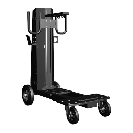
Machine description – quick overview Front view / side view from left Machine description – quick overview Front view / side view from left Figure 4-1 Item Symbol Description Cross arm Upper device attachment Securing element Clamping belt for attaching the shielding gas cylinder Wheels, fixed castors Support bracket (BK260) Lower device attachment (Picomig 185, -355;... -
Page 9: Design And Function
Design and function System overview Design and function System overview Figure 5-1 099-008632-EW501 05.12.2019... - Page 10 Design and function System overview Item Symbol Description Transport cart Transport cart + one system component (e.g. power source) Transport cart + two system components (e.g. power source + cooling module) Transport cart + one system component (e.g. toolbox + power source) Cross arm and holder for wire feeder Pivot support (360°) for wire feeders Pivot support for a wire feeders D200...
-
Page 11: Assembling The Transport Cart
Design and function Assembling the transport cart Assembling the transport cart WARNING Improper work carried out! In the event of improper work carried out on the display stand, the display stand may lose stability, tip over and result in serious injury! •... -
Page 12: Final Assembly
Design and function Assembling the transport cart Figure 5-3 Description Item number Item Quan- tity M8 x 16, hexagonal pan screw 094-007803-00000 Fender washer 064-000793-00000 5.2.1 Final assembly WARNING Danger due to failure to carry out the final inspection! Parts that are incorrectly fitted or that become loose are a source of danger. •... -
Page 13: Attach The System Component To The Transport Cart
Design and function Attach the system component to the transport cart Attach the system component to the transport cart CAUTION Improperly secured equipment! Equipment, equipment combinations and accessories incorrectly fastened onto trans- port systems can tip over during transport and cause injuries! •... - Page 14 Design and function Attach the system component to the transport cart Figure 5-5 Item Symbol Description Support bracket (BK260) Lower device attachment (Picomig 185, -355; Phoenix 355, -405, -505; Taurus 355, -405, -505; cool50) Pan screw, M8 x 16 mm Cross arm Upper device attachment System components...
-
Page 15: Intermediate Hose Package Strain Relief
Design and function Attach the system component to the transport cart 5.3.1 Intermediate hose package strain relief Property damage due to strain relief not installed or not installed correctly! The strain relief absorbs tensile forces on cables, plugs and sockets. If strain reliefs are not installed or not installed correctly, the connector plugs or sockets may be damaged. -
Page 16: Securing The Shielding Gas Cylinder
Design and function Securing the shielding gas cylinder Securing the shielding gas cylinder WARNING Risk of injury due to improper handling of shielding gas cylinders! Improper handling and insufficient securing of shielding gas cylinders can cause serious injuries! • Secure shielding gas cylinders using the standard fastening elements on the unit (chain/belt)! •... -
Page 17: Transport And Installation
Design and function Transport and installation Transport and installation WARNING Risk of accident due to improper transport of machines that must not be lifted! Do not lift or suspend the machine! The machine can drop and cause injuries! The handles, straps or brackets are suitable for transport by hand only! •... -
Page 18: Maintenance, Care And Disposal
Maintenance, care and disposal General Maintenance, care and disposal General DANGER Risk of injury due to electrical voltage after switching off! Working on an open machine can lead to fatal injuries! Capacitors are loaded with electrical voltage during operation. Voltage remains present for up to four minutes after the mains plug is removed. -
Page 19: Maintenance Work, Intervals
A periodic test according to IEC 60974-4 "Periodic inspection and test" has to be carried out. In addition to the regulations on testing given here, the relevant local laws and regulations must also be observed. For more information refer to the "Warranty registration" brochure supplied and our information regarding warranty, maintenance and testing at www.ewm-group.com! 099-008632-EW501 05.12.2019... -
Page 20: Disposing Of Equipment
• Information about returning used equipment or about collections can be obtained from the respective municipal administration office. • In addition to this, returns are also possible throughout Europe via EWM sales partners. 099-008632-EW501 05.12.2019... -
Page 21: Technical Data
Technical data Trolly 55-5 Technical data Performance specifications and guarantee only in connection with original spare and replacement parts! Trolly 55-5 max. Height (Shielding gas cylinder) 1660 mm 65.35 inch max. Diameter (Shielding gas cylin- 229 mm der) 9 inch... -
Page 22: Accessories
ON PS Trolly 55-5 / Pivot support 092-002634-00000 55-6 drive D200 ON Case Tool box for mounting to Trolly 55-5/6 092-002899-00000 ON TR Trolly 55 Cross arm and holder for wire feeder Trolly 55-5 092-002700-00000 and Trolly 55-6 099-008632-EW501 05.12.2019... -
Page 23: Appendix
Appendix Searching for a dealer Appendix Searching for a dealer Sales & service partners www.ewm-group.com/en/specialist-dealers "More than 400 EWM sales partners worldwide" 099-008632-EW501 05.12.2019...
Need help?
Do you have a question about the Trolly 55-5 and is the answer not in the manual?
Questions and answers