Cornelius UFB1 Installation And Service Manual
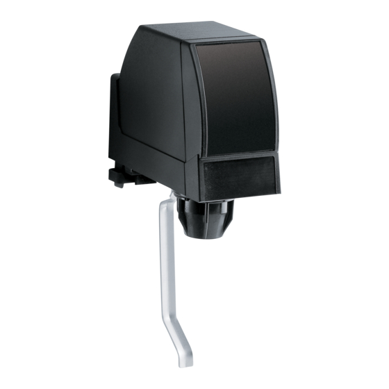
Dispensing valve
Hide thumbs
Also See for UFB1:
- Operator's manual (40 pages) ,
- Training manual (36 pages) ,
- Illustrated parts list (4 pages)
Table of Contents
Advertisement
Quick Links
Advertisement
Table of Contents

Related Manuals for Cornelius UFB1


Summary of Contents for Cornelius UFB1
- Page 1 Installation and service manual PUSH Dispensing valve UFB1...
- Page 2 Dispensing valve UFB1 portion control: Part number: 741000401 (3 oz) UFB1 push button: Part number: 741000399 (3 oz) | 740001214 (4 oz) UFB1 dispensing lever: Part number: 741000403 (3 oz) | 740001213 (4 oz) UFB1 OptiFill: Part number: 741000405 (3 oz)
-
Page 3: Table Of Contents
3.1.1 Dispensing valve UFB1 portion control ........... . - Page 4 ............. . Troubleshooting table Installation and service manual Dispensing valve Cornelius Deutschland GmbH UFB1 Document no. TD2004100...
-
Page 5: Safety
Improper use of the dispensing valve, and unauthorised modifications to the dispensing valve and its components may cause per- sonal injury and equipment damage for which Cornelius Deutschland GmbH shall assume no liability. Improper use of the dispens- ing valve is prohibited. -
Page 6: Transport And Packaging
Transport and packaging Choose a suitable packaging when returning the dispensing valve itself or one of its components to Cornelius Deutschland GmbH, e.g. for repairs. In particular, make sure that the dispensing valve and any components are protected from shock/impact, moisture, dirt and electrostatic discharge (ESD). -
Page 7: Description
Description The dispensing valve UFB1 offers two fast flow rates, see 3.4. A 3 oz valve with a flow rate of 1.5 – 3 oz/sec (45 – 90 ml/sec) and a 4 oz valve with a flow rate of 2 – 4 oz/sec (60 – 120 ml/sec) are available. A prerequisite for using the 4 oz valve is the operation of a base unit designed to refrigerate and convey. -
Page 8: Dispensing Valve Ufb1 Push Button
Description 3.1.2 Dispensing valve UFB1 push button The dispensing valve UFB1 push button comprises the following components: Fig. 2 Valve cover rear Outlet nozzle Flow controller Valve head Flow controller seal Pull-type solenoid Block mount 10 Microswitch Block mount seal... -
Page 9: Dispensing Valve Ufb1 Dispensing Lever
Description 3.1.3 Dispensing valve UFB1 dispensing lever The dispensing valve UFB1 dispensing lever comprises the following components: Fig. 3 Valve cover rear Dispensing lever Flow controller Outlet nozzle Flow controller seal Baffle with diffusor Block mount 10 Valve head Block mount seal... -
Page 10: Dispensing Valve Ufb1 Optifill
Description 3.1.4 Dispensing valve UFB1 OptiFill The dispensing valve UFB1 OptiFill comprises the following components: Fig. 4 Valve cover rear Outlet nozzle Flow controller Baffle with diffusor Flow controller seal 10 Valve head Block mount 11 Pull-type solenoid Block mount seal... -
Page 11: Juice Dispensing Nozzle
From there, the beverage runs into the cup. An optional soda lever is available for the dispensing valve UFB1. Actuating the soda lever opens only the soda path in the valve, so that only soda, without syrup or concentrate, flows through the block mount into the flow controller, through the valve head into the dispensing nozzle and then into the cup. -
Page 12: Installation/Removal
Non-compliance with these laws, regulations and guidelines may result in death, serious injury or equipment damage. The dispensing valve UFB1 is suitable for installation on various base units (overcounter cooler or tower). The dispensing valve UFB1 is attached to the dispensing valve support via the block mount. -
Page 13: Removing The Dispensing Valve
5. Attach the soda lever (Fig. 13/2) using the fastening bolt (Fig. 13/3). Do not overtighten the fastening bolt (Fig. 13/3). Finishing tasks 1. Mount the dispensing valve, see chapter 4.1. Fig. 13 Cornelius Deutschland GmbH Installation and service manual Dispensing valve Document no. TD2004100 UFB1 Version 15/03/2019, Index 0... -
Page 14: Removing The Soda Lever
Every 3 months Baffle seal Perform a visual inspection; see chapter 5.2 Every 3 months Dispensing valve, interior Clean the valves; see chapter 5.3 Installation and service manual Dispensing valve Cornelius Deutschland GmbH UFB1 Document no. TD2004100 Version 15/03/2019, Index 0... -
Page 15: Carrying Out A Visual Inspection Of The Seals On The Diffusor And Baffle
Fig. 18 Standard dispens- ing nozzle NOTICE! The outlet nozzle is easier to insert into the dispensing valve if it is moistened with water beforehand. Cornelius Deutschland GmbH Installation and service manual Dispensing valve Document no. TD2004100 UFB1 Version 15/03/2019, Index 0... -
Page 16: Cleaning The Valves
Cleaning the dispensing valve is only possible if the dispensing valve is mounted on a base unit. A description of how to clean the valve can be found in the relevant base unit installation and service manual. Installation and service manual Dispensing valve Cornelius Deutschland GmbH UFB1 Document no. TD2004100... -
Page 17: Repairs
1956 NOTICE! The replacement procedure for the front valve cover is exactly the same on the dispensing valves UFB1. Replacement is described here analogously using an example. 1. Push the front valve cover (Fig. 20/1) upwards and lift the front valve cover (Fig. 20/1) off the dispensing valve (Fig. -
Page 18: Replacing The Rear Valve Cover
1950 NOTICE! The replacement procedure for the rear valve cover is exactly the same on the dispensing valves UFB1. Replacement is described here analogously using an example. 1. Push the rear valve cover (Fig. 22/1) forwards and lift the rear valve cover (Fig. 22/1) upwards. -
Page 19: Replacing The Optifill Module
Spare parts ID/reference Qty/amount Comment UFB1 OptiFill: Module 4391 1. Disconnect the plug (Fig. 27/1) of the OptiFill module (Fig. 27/5). 2. Disconnect the electrical cables (Fig. 27/2) for the OptiFill module (Fig. 27/5) on the pull-type solenoid (Fig. 27/6). -
Page 20: Replacing The Flow Controller
7. Secure the flow controller (Fig. 32/1) with the dispensing valve lock (Fig. 32/3). Fig. 32 Finishing tasks 1. Mount the dispensing valve, see chapter 4.1. Installation and service manual Dispensing valve Cornelius Deutschland GmbH UFB1 Document no. TD2004100 Version 15/03/2019, Index 0... -
Page 21: Replacing The Block Mount
4. Install the block mount, see chapter 4.1. Fig. 33 Replacing the microswitch Prerequisites References The dispensing valve has been removed. see chapter 4.2 UFB1 OptiFill: The OptiFill module has been removed. see chapter 6.4 Spare parts ID/reference Qty/amount Comment Microswitch... -
Page 22: Replacing The Pull-Type Solenoid
4) with the rear tabs into the valve body (Fig. 36/3) and carefully pushing the base plate (Fig. 36/4) upwards until the side tabs (Fig. 36/1) engage. Fig. 36 Finishing tasks 1. Only on UFB1 OptiFill: Mount the OptiFill module, see chapter 6.4. 2. Mount the dispensing valve, see chapter 4.1. Replacing the pull-type solenoid Prerequisites References The dispensing valve has been removed. -
Page 23: Replacing The Dispensing Lever
UFB1 OptiFill: Lever 560003252 NOTICE! The procedure for replacing the dispensing lever for the dispensing valve UFB1 dispensing lever and the dis- pensing valve UFB1 OptiFill are exactly the same. Replacement of the dispensing lever is described here analogously using an example. -
Page 24: Replacing The Dispensing Nozzle
Fig. 44 Juice dispensing nozzle NOTICE! The outlet nozzle is easier to insert into the dispensing valve if it is moistened with water beforehand. Installation and service manual Dispensing valve Cornelius Deutschland GmbH UFB1 Document no. TD2004100 Version 15/03/2019, Index 0... - Page 25 6. Lock the outlet nozzle in the dispensing valve by turning. Make sure that the dispensing nozzle is inserted correctly as otherwise the beverage cannot be dispensed correctly. Fig. 45 Cornelius Deutschland GmbH Installation and service manual Dispensing valve Document no. TD2004100 UFB1...
-
Page 26: Configuring And Adjusting
The dispensing valve module is factory-programmed with fill times. These fill times for each beverage size are listed in the following table: Beverage size Fill time 2 seconds 3 seconds 4 seconds 6 seconds Tab. 7-1 Fill times factory setting Installation and service manual Dispensing valve Cornelius Deutschland GmbH UFB1 Document no. TD2004100 Version 15/03/2019, Index 0... -
Page 27: Standard" Configuration Mode
6. Exit configuration mode by pressing the program button (Fig. 47/3) or the “Start & Stop” button (Fig. 47/4) for 5 seconds. The “PGM” indicator (Fig. 47/5) goes out. The last fill time, pause and top-up time set for each beverage size is stored. Cornelius Deutschland GmbH Installation and service manual Dispensing valve Document no. TD2004100... -
Page 28: Incremental" Configuration Mode
7. Exit configuration mode by pressing the program button (Fig. 49/2) or the “Start & Stop” button (Fig. 49/3) for 5 seconds. The “PGM” indicator (Fig. 49/4) goes out. The fill times for the beverage sizes are reset to the factory settings. Installation and service manual Dispensing valve Cornelius Deutschland GmbH UFB1 Document no. TD2004100 Version 15/03/2019, Index 0... -
Page 29: Procedure For Non-Reactive Modules
Fig. 51 The fill time is configured. 4. Exit configuration mode by pressing the program button (Fig. 51/2) for 3 seconds. The LED indicator (Fig. 51/1) goes out. Cornelius Deutschland GmbH Installation and service manual Dispensing valve Document no. TD2004100 UFB1... - Page 30 4. To increase the flow rate, turn the flow valve (Fig. 54/2) 1/4 turn anti-clockwise. Finishing tasks 1. Mount the rear valve cover, see chapter 6.2. Fig. 54 Installation and service manual Dispensing valve Cornelius Deutschland GmbH UFB1 Document no. TD2004100 Version 15/03/2019, Index 0...
- Page 31 (see docu- mentation on the CO system) Base unit error See base unit documentation supply too low Change the CO bottle Cornelius Deutschland GmbH Installation and service manual Dispensing valve Document no. TD2004100 UFB1 Version 15/03/2019, Index 0...
- Page 32 Cornelius Deutschland GmbH Tel.: +49 (0) 21 73 / 79 3 – 0 Carl-Leverkus-Str. 15 Fax: +49 (0) 21 73 / 77 4 – 38 40764 Langenfeld E-Mail: info@cornelius.com Germany...
Need help?
Do you have a question about the UFB1 and is the answer not in the manual?
Questions and answers