Table of Contents
Advertisement
Quick Links
Advertisement
Table of Contents

Subscribe to Our Youtube Channel
Related Manuals for Cornelius VIPER FMFV


Summary of Contents for Cornelius VIPER FMFV
- Page 1 VIPER FROZEN MULTI FLAVOUR VALVE INSTALLATION AND OPERATION MANUAL Release Date: October 15, 2018 Publication Number: 919000012INS Revision Date: October 16, 2019 Revision: B Visit the Cornelius web site at www.cornelius.com for all your Literature needs.
- Page 2 Commercial Warranty. Cornelius will not be responsible for any repair, replacement or other service required by or loss or damage resulting from any of the following occurrences, including but not limited to, (1) other than normal and proper use...
-
Page 3: Table Of Contents
FMFV - Installation Manual TABLE OF CONTENT Safety Instructions ........... . . 1 Safety Overview . - Page 4 FMFV - Installation Manual Component Service ........... 31 Diffuser Replacement .
-
Page 5: Safety Instructions
Keep your unit in proper working condition and do not allow unauthorized modifications to the unit. NOTE: The dispenser is not designed for a wash-down environment and MUST NOT be placed in an area where a water jet could be used. Publication Number: 919000012INS - 1 - © 2018-19, Cornelius Inc. -
Page 6: Qualified Service Personnel
• Children should be supervised to ensure that they do not play with the appliance. © 2018-19, Cornelius Inc. - 2 - Publication Number: 919000012INS... -
Page 7: Installation
ELIVERY NSPECTION NPACKING NOTE: Cornelius is not responsible for damaged freight. If damage is found, you must save all packaging material and contact the freight carrier. Failure to contact the carrier within 48 hours of receipt may void your claim. -
Page 8: Compressed Air Connection
The power circuit must have 1 amp overload protection, such as a circuit breaker or fuse that meets local and national electrical codes. NOTE: Viper & FMFV kit uses different power wall outlets. © 2018-19, Cornelius Inc. - 4 - Publication Number: 919000012INS... -
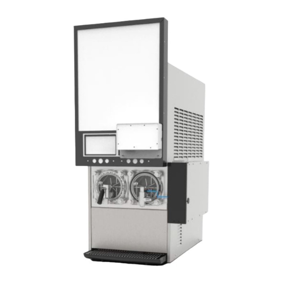
Page 9: Fmfv- System Overview
User Interface (Touch Screen) 122.4 X 91.44 mm (7 in.) Shipping Weight 12.27 Kg (27 lb) Operating Pressure 276-310 k Pa (40-50 psig) Agency Listing NSF, CE IP Rating IP CLASS 20 Publication Number: 919000012INS - 5 - © 2018-19, Cornelius Inc. -
Page 10: Physical Dimensions
Screw driver, phillips #2 & #1 Oetiker crimping tool Tube cutter Needle nose plier 8”/200 mm Snap ring plier 8”/200 mm 3/32” Allen key Adjustable Wrench 30 mm Safety Gloves Safety Goggles & Shoes © 2018-19, Cornelius Inc. - 6 - Publication Number: 919000012INS... -
Page 11: Fmfv Kit Includes Following Key Components
NOTE: Only one kit can be installed on the left side of the unit as a default position. But it can be installed, either left or right side of the unit. One trained technician required to install FMFV Kit. • C-Box • UI Display • Pump Assembly • Valve Assembly Publication Number: 919000012INS - 7 - © 2018-19, Cornelius Inc. -
Page 12: Installation Of C-Box
8 mounting screws by using screw driver, phillips #2. Open front door to access the MFV valves, Solenoid valves and PCB brackets. SOLENOID MFV VALVE VALVE BRACKET Figure 4. © 2018-19, Cornelius Inc. - 8 - Publication Number: 919000012INS... - Page 13 1/4” bradded hose Connect the other end of the bradded hose to push connector. NOTE: Clamp compressed air tubes by oeiteker. 910002210 Push to connect 1/4” Bradded hose fitting Figure 7. Publication Number: 919000012INS - 9 - © 2018-19, Cornelius Inc.
- Page 14 USB terminal to PCB board b. Fork terminals: Connect the fork terminal to the shown location in terminal block by unscrewing the screws of terminal block Fork terminal USB Cable Figure 10. © 2018-19, Cornelius Inc. - 10 - Publication Number: 919000012INS...
- Page 15 Pinching area Figure 12. Dummy threaded Hole Close with screw Replace the bottom screw as per the mounting requirement left or right and cover the dummy hole by screw. Figure 13. Publication Number: 919000012INS - 11 - © 2018-19, Cornelius Inc.
- Page 16 After placing the C-box on the unit assemble C-box Bottom (910001939) to the bottom louver on the viper and fasten to C-box using screw M4 X 10 Bottom louver Holding bracket Figure 16. © 2018-19, Cornelius Inc. - 12 - Publication Number: 919000012INS...
-
Page 17: Installation Of Valve
Refer the procedure mentioned in viper service manual for removing Motorman and SPH/Delta valves. Assemble the Valve (910002035) to face plate using retainer ring provided with valve assembly NOTE: Use snap ring plier to remove retainer ring. Retaining ring Figure 18. Publication Number: 919000012INS - 13 - © 2018-19, Cornelius Inc. - Page 18 C-box mounted on viper. Tighten the grub screw to secure the position of air valve assembly. Quick connector orientation Figure 21. © 2018-19, Cornelius Inc. - 14 - Publication Number: 919000012INS...
- Page 19 Figure 23. Air inlet hose (blue colour hose) goes Quick Connector into the Quick connector in the pneumatic valve and ensure the hose fixed properly. Figure 24. Publication Number: 919000012INS - 15 - © 2018-19, Cornelius Inc.
- Page 20 Figure 25. Connect the power cord to the appliance inlet. Appliance Inlet Figure 26. Connect the power cord of the viper. For Brix Setting and Brix adjustment refer Viper manual. © 2018-19, Cornelius Inc. - 16 - Publication Number: 919000012INS...
-
Page 21: Installation Of Syrup Pump Assembly
Connect the air pressure regulator outlet to one end of the “Four way connector”. Figure 30. The other end of the “Four way connector”, supply the air to purge and hammering solenoids Publication Number: 919000012INS - 17 - © 2018-19, Cornelius Inc. - Page 22 The inlet of air regulator must be connected to air supply only. The outlet of air regulator will be going to the airline “Four way connector” provided on the syrup pump assembly. Figure 31. © 2018-19, Cornelius Inc. - 18 - Publication Number: 919000012INS...
-
Page 23: Installation Of Ui Display
#1 Figure 33. Assemble the “Display mounting Magnet” by Phillips screw depending on the side of display mounting Hook the assembled Display bracket on the Viper merchandiser. Figure 34. Publication Number: 919000012INS - 19 - © 2018-19, Cornelius Inc. - Page 24 Tie the Magnet to the wire through cable tie and route it on the Viper. Magnet Figure 35. Connect the Power cord to the main power Supply and switch ON the FMFV Kit and viper © 2018-19, Cornelius Inc. - 20 - Publication Number: 919000012INS...
-
Page 25: Operation
If the Valve has restricted flow use, “ICE HAMMER” to activate the valve via compressed air and clears the way to dis- pense. Flavour Icons The Unit has flexibility to dispense Publication Number: 919000012INS - 21 - © 2018-19, Cornelius Inc. -
Page 26: Adjustments
8. After above steps, take five flavours volume samples at one drink per minute for evaluation Specification: Flavour volume limit is target flavour volume ±2ml for 3 seconds NOTE: Flavour solenoid range is 0-9 ml/sec. © 2018-19, Cornelius Inc. - 22 - Publication Number: 919000012INS... -
Page 27: Flavour Syrup Line Cleaning & Sanitizing
Take 20 liters (5.28 gallon) bucket and fill Portable water approximately 12 liters (3.1 gal- lon) of 20°c - 38°C (70°F - 100°F) add 39 g (1.3 Oz) of liquid dish washing detergent. Mix well to create detergent solution. Publication Number: 919000012INS - 23 - © 2018-19, Cornelius Inc. - Page 28 Press “MENU” Icon on the Display module. Figure 41. Input the password by Number tab and press “ENTER”. Figure 42. Menu setting window will open. Press “BRIX/SANITIZATION” tab. Figure 43. © 2018-19, Cornelius Inc. - 24 - Publication Number: 919000012INS...
- Page 29 IMPORTANT: The sanitizing solution must not exceed 200 PPM chlorine. Immerse all BIB connectors con- nected with sanitizing fitting (P/N 28688) in the bucket having sani- tizing solution. Figure 46. Publication Number: 919000012INS - 25 - © 2018-19, Cornelius Inc.
- Page 30 Take 20 liters (5.28 gallon) bucket and fill water Approximately 12 Liter (3 gallon). Immerse all BIB connectors con- nected with sanitizing fitting (P/N 28688) in the bucket having rinse water. Figure 47. Repeat the steps From #6 to #11 © 2018-19, Cornelius Inc. - 26 - Publication Number: 919000012INS...
-
Page 31: Software And Firmware Update
Safely remove the USB drive from your computer. Plug the storage media in to USB port Located under the left side of display (connect to any one port) Figure 50. Publication Number: 919000012INS - 27 - © 2018-19, Cornelius Inc. - Page 32 13795 to get access to technician menu. Figure 51. Figure 52. Press Upgrade Software Icon on the screen. Figure 53. Select the right upgrade file; Example: FrozenMFV-QT-07.23.18- MCDv1-Driver.Zip Figure 54. © 2018-19, Cornelius Inc. - 28 - Publication Number: 919000012INS...
- Page 33 Figure 56. Wait till display reboots. Repeat the step #6 to #11, Upgrade software one more time. Figure 57. Press menu and enter the technician password code 13795. Figure 58. Publication Number: 919000012INS - 29 - © 2018-19, Cornelius Inc.
- Page 34 Available space should be more than 800MB Figure 60. In “INFO” screen press reboot system. Figure 61. Display will reboot with new upgrade software and is ready to use. Figure 62. © 2018-19, Cornelius Inc. - 30 - Publication Number: 919000012INS...
-
Page 35: Component Service
5. Remove the side panel, Disconnect the inlet and out let pneumatic connections of the mac valve 6. Disconnect the electrical harness 7. Remove existing Mac Valve and assemble new mac valve Publication Number: 919000012INS - 31 - © 2018-19, Cornelius Inc. -
Page 36: Trouble Shooting
1. Need to replace with new Side 1. Failure of side seal Seal (Service call) Leakage from Side 2. Failure of injector cover 2. Need to replace Injector seal © 2018-19, Cornelius Inc. - 32 - Publication Number: 919000012INS... -
Page 37: Plumbing Diagram
2. MFV solenoid knob 2. Adjust Brix less flow flavour opened fully. 3. Check the plumbing connection 3. MFV solenoid plumbing for no pinch or leakage. pinch/leakage Plumbing Diagram Figure 63. Publication Number: 919000012INS - 33 - © 2018-19, Cornelius Inc. -
Page 38: Wiring Diagram
FMFV - Installation Manual Wiring Diagram. Figure 64. © 2018-19, Cornelius Inc. - 34 - Publication Number: 919000012INS... - Page 40 Cornelius Inc. www.cornelius.com...
Need help?
Do you have a question about the VIPER FMFV and is the answer not in the manual?
Questions and answers