Cornelius UF-1 POST-MIX VALVE Operator's Manual
Hide thumbs
Also See for UF-1 POST-MIX VALVE:
- Training manual (32 pages) ,
- Illustrated parts list (4 pages) ,
- Bulletin (2 pages)
Table of Contents

Related Manuals for Cornelius UF-1 POST-MIX VALVE


Summary of Contents for Cornelius UF-1 POST-MIX VALVE
- Page 1 UF-1 POST-MIX VALVE Operator’s Manual Release Date: January 11, 2021 Publication Number: 315222002OPR Revision Date: January 11, 2021 Revision: D Visit the Cornelius web site at www.cornelius.com for all your Literature needs.
- Page 2 This Product is warranted only as provided in Cornelius’ Commercial Warranty applicable to this Product and is subject to all of the restrictions and limitations contained in the Commercial Warranty.
- Page 3 This Product is warranted only as provided in Cornelius’ Commercial Warranty applicable to this Product and is subject to all of the restrictions and limitations contained in the Commercial Warranty.
-
Page 4: Table Of Contents
TABLE OF CONTENTS Safety Instructions ............. . 1 Read And Follow All Safety Instructions . - Page 5 Service And Maintenance ............13 Cleaning Dispensing Valve .
-
Page 6: Safety Instructions
UF-1 Post- Mix Valve Operation Manual SAFETY INSTRUCTIONS OLLOW AFETY NSTRUCTIONS • Read and follow ALL SAFETY INSTRUCTIONS in this manual and any warning/caution labels on the unit (decals, labels or laminated cards). • Read and understand ALL applicable OSHA (Occupational Safety and Health Administration) safety regulations before operating this unit. -
Page 7: Safety Precautions
UF-1 Post-Mix Valve Operation Manual AFETY RECAUTIONS This unit has been specifically designed to provide protection against personal injury. To ensure continued protection observe the following: Disconnect power to the unit before servicing, following all lock out/tag out procedures established by the user. -
Page 8: Introduction
UF-1 Post- Mix Valve Operation Manual INTRODUCTION The UF-1 (interchangeable with UFB–1) valve provides the fast flow capabilities required in today’s business world; simplicity to provide dependability and ease of repair when needed and easy conversion to any of the available pouring formats. Read this manual carefully to learn how to operate and maintain this valve. -
Page 9: Optifill™ Dispensing Control
UF-1 Post-Mix Valve Operation Manual ™ PTIFILL DISPENSING ONTROL Operate the OptiFill™ model by pressing a cup against the lever and LEVER allowing it to remain there. The valve will automatically shut off when the liquid from the cup touches the lever. There is also an automatic top-off delay that can be disabled if desired. -
Page 10: Alternate Dispensing Modules
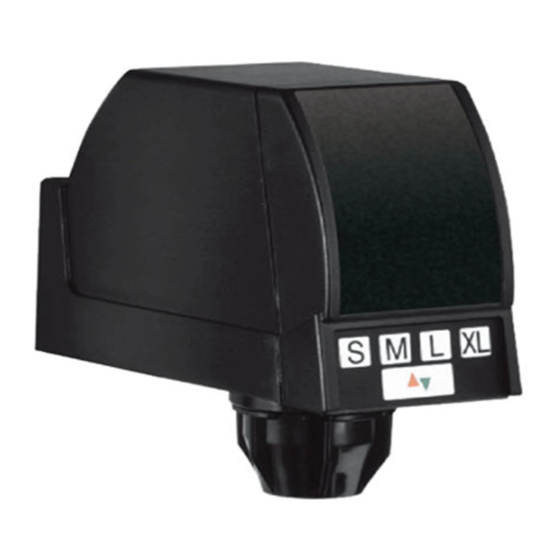
UF-1 Post- Mix Valve Operation Manual LTERNATE ISPENSING ODULES UF‐1 M ANUAL ISPENSE UTTON • Integrated styling with other control modules. • Manual dispense “PUSH” for self–serve applications UF‐1 P ORTION ONTROL • Four dispense sizes and manual pour. • Fully programmable from front panel with Hidden Switch. -
Page 11: Operation Instructions
UF-1 Post-Mix Valve Operation Manual OPERATION INSTRUCTIONS UF‐1 D ISPENSING ALVE UF‐1 E LECTRIC ISPENSING ONTROL 1. Press cup or glass against dispensing valve lever and dispense product until cup or glass is full. Then release lever LEVER PTIONAL ATER EVER 1. -
Page 12: Optifill Dispensing Valve Control
UF-1 Post- Mix Valve Operation Manual PTIFILL ISPENSING ALVE ONTROL UF–1 D ™ D ISPENSING ALVE PTIFILL ISPENSING 1. Place cup (with ice if desired) against the operating lever and allow it to stay there as the cup fills. 2. When the cup is full and liquid from the cup touches the lever the valve will shut off. -
Page 13: Portion Control Operation
UF-1 Post-Mix Valve Operation Manual ORTION ONTROL PERATION NOTE: You must momentarily depress one of the four drink–size switches, then release before the drink will dispense. You can use the cancel/ pour switch for the following two separate dispensing functions: 1. -
Page 14: Adjustments
UF-1 Post- Mix Valve Operation Manual ADJUSTMENTS DJUSTING ORTION ONTROL HANGING RINK ISPENSED Use the programming mode to set the portion size to the desired setting. To enter the programming mode, the following criteria must be met: 1. There is no active dispensing cycle in progress. CCESSING ROGRAMMING 1. -
Page 15: Optifill™ Dispensing Valve Control
UF-1 Post-Mix Valve Operation Manual XITING ROGRAMMING 1. Press and hold the hidden switch for 3 seconds. When you have exited the program mode, the timer values stored in temporary memory will be written to permanent storage and the “PGM” LED will go off. -
Page 16: Water Flow Rate
UF-1 Post- Mix Valve Operation Manual XITING ROGRAM To leave the programming mode, press and hold the PROGRAM SWITCH for 3 seconds. ATER ISPENSING ALVE ATER Flowasher Water flowasher is at a fixed water flow rate and is nonadjustable. ISPENSING ALVE DJUSTABLE... -
Page 17: Adjust Water-To-Syrup Ratio
UF-1 Post-Mix Valve Operation Manual ‐ ‐ DJUST ATER SYRUP ATIO UF‐1 D ISPENSING ALVE NOTE: On a dispensing valve with adjustable water flow regulator make sure water flow rate is adjusted to your requirement before adjusting the syrup to water ratio.... -
Page 18: Service And Maintenance
UF-1 Post- Mix Valve Operation Manual SERVICE AND MAINTENANCE LEANING ISPENSING ALVE NOTE: The solenoid is not shown to provide a clear view. it is not necessary to remove the solenoid. EEKLY OZZLE LEANING ROCEDURE This cleaning procedure must be performed each week or more often if needed to maintain cleanliness of the nozzle and inner noz- 1. -
Page 19: Remove And Replace Switch
UF-1 Post-Mix Valve Operation Manual EMOVE EPLACE WITCH EMOVAL 1. Remove dispensing valve cover. Lift front cover straight up for 1/4 inch and pull forward. Slide rear cover forward 1/4 inch and lift off. 2. Remove valve from dispenser by releasing the latch with your thumb and pressing the top dovetail. -
Page 20: Remove And Replace Water Flowasher Assembly
UF-1 Post- Mix Valve Operation Manual 9. If syrup flow regulator was removed, check dispensing valve for water-to-syrup ratio of dispensed product and, if necessary, adjust as instructed. 10. Install dispensing valve cover and secure. NOTE: New O‐Rings(4) P/N 4073 must be installed on the flow control assembly before its installation in the dispensing valve body EMOVE EPLACE... -
Page 21: Remove And Replace Inlet Banjo Valve
UF-1 Post-Mix Valve Operation Manual EMOVE EPLACE NLET ANJO ALVE EMOVAL 1. Remove dispensing valve covers. Lift front cover straight up for 1/ 4 inch and pull for-ward. Slide rear cover forward 1/4 inch and lift off. 2. Disconnect dispensing valve wiring harness connector from unit wiring harness connector. -
Page 22: Remove And Replace Control Modules
UF-1 Post- Mix Valve Operation Manual EMOVE EPLACE ONTROL ODULES EMOVAL 1. Remove dispensing valve covers from valve. 2. Tag electrical wires for identification. Then disconnect Control module wires from solenoid coil and unit wiring harness connector. See electrical diagram, Figure 1, 2, 3, 4. -
Page 23: Troubleshooting
UF-1 Post-Mix Valve Operation Manual TROUBLESHOOTING IMPORTANT: Only qualified personnel should service internal components or electrical wiring. WARNING If repairs are to be made to carbonated water system, disconnect electrical power to Cooling Unit, shut off plain water and CO2 supplies, and relieve the carbonated water system pressure before proceeding. If repairs are to be made to syrup system, remove quick disconnects from applicable syrup tank, then relieve the system pressure before proceeding. - Page 24 UF-1 Post- Mix Valve Operation Manual ONLY CARBONATED WATER Syrup quick disconnects not secure. Secure the syrup quick disconnects. DISPENSED. Out of syrup. Replenish syrup supply as instructed. Syrup CO regulator not properly Adjust syrup CO regulator. adjusted. Inoperable dispensing valve. Repair dispensing valve.
-
Page 25: Reference Material
UF-1 Post-Mix Valve Operation Manual REFERENCE MATERIAL UF‐1 D IRING IAGRAM ISPENSING ALVE Figure 1. UF‐1 S IRING IAGRAM ERVE ISPENSING ALVE Figure 2. Publication Number: 315222002OPR - 20 - © 2017-2021, Marmon Foodservice Technologies, Inc. -
Page 26: Wiring Diagram For Uf-1 Dispensing Valve With Portion Control
UF-1 Post- Mix Valve Operation Manual UF‐1 D IRING IAGRAM ISPENSING ALVE ORTION ONTROL Figure 3. UF‐1 O IRING IAGRAM PTIFILL ISPENSING ALVE Figure 4. © 2017-2021, Marmon Foodservice Technologies, Inc. - 21 - Publication Number: 315222002OPR... - Page 27 Cornelius Inc. www.cornelius-usa.com...
Need help?
Do you have a question about the UF-1 POST-MIX VALVE and is the answer not in the manual?
Questions and answers