Altronix Maximal3FD Installation Manual
Access power controllers with power supplies
Hide thumbs
Also See for Maximal3FD:
- Installation manual (16 pages) ,
- Installation manual (16 pages) ,
- Installation manual (16 pages)
Table of Contents
Advertisement
Quick Links
Access Power Controllers with
Power Supplies
Installation Guide
Models Include:
Maximal3FD
- 12VDC @ 4.6A or 24VDC @ 5.2A.
- Sixteen (16) PTC protected power-limited outputs.
Maximal5FD
- 12VDC @ 8.6A.
- Sixteen (16) PTC protected power-limited outputs.
Maximal7FD
- 24VDC @ 9.2A.
- Sixteen (16) PTC protected power-limited outputs.
Rev. MSFD052419
Installing Company: ________________ Service Rep. Name: ______________________________________
Address: ___________________________________________________ Phone #: _____________________
Altronix Corp.
140 58th St. Brooklyn, NY
More than just power.
TM
Advertisement
Table of Contents

Related Manuals for Altronix Maximal3FD


Summary of Contents for Altronix Maximal3FD
- Page 1 Access Power Controllers with Power Supplies Installation Guide Models Include: Maximal3FD - 12VDC @ 4.6A or 24VDC @ 5.2A. - Sixteen (16) PTC protected power-limited outputs. Maximal5FD - 12VDC @ 8.6A. - Sixteen (16) PTC protected power-limited outputs. Maximal7FD - 24VDC @ 9.2A.
-
Page 2: Table Of Contents
Enclosure Dimensions ............pg. 15 - 2 - Maximal3FD/Maximal5FD/Maximal7FD Access Power Controllers (PTC) -
Page 3: Maximalfd Series Overview
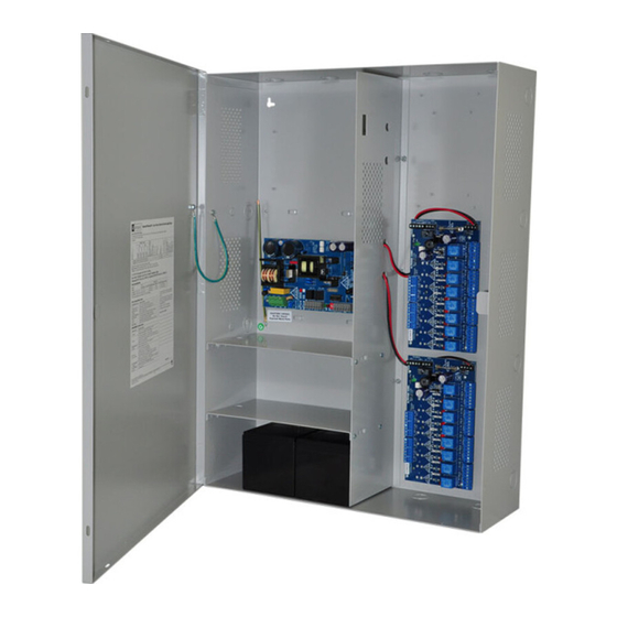
MaximalFD Series Overview: Altronix MaximalFD Access Power/Controllers distribute and switch power to access control systems and accessories. They convert a 120VAC 60Hz input into sixteen (16) independently controlled 12VDC or 24VDC PTC protected protected outputs. The outputs are activated by an open collector sink or normally open (NO) dry trigger input from an Access Control System, Keypad, Push Button, REX PIR, etc. -
Page 4: Maximal Series Features
• Short circuit and overload protection. • Enclosure accommodates up to four (4) 12VDC/12AH batteries. Enclosure dimensions (H x W x D): 26” x 19” x 6.25” (660.4mm x 482.6mm x 158.8mm). - 4 - Maximal3FD/Maximal5FD/Maximal7FD Access Power Controllers (PTC) -
Page 5: Maximalfd Installation Instructions
There are no user serviceable parts inside. Refer installation and servicing to qualified service personnel. 3. Select desired DC output voltage by setting SW1 to the appropriate position on the Maximal3FD power supply (Fig. 1a, pg. 9). Maximal5FD power supply is factory set at 12VDC and Maximal7FD power supply is factory set at 24VDC. -
Page 6: Maintenance
14. Installation of Tamper Switch (Fig. 3b, pg. 10): Mount UL Listed tamper switch (Altronix model TS112 or equivalent) at the top of the enclosure. Slide the tamper switch bracket onto the edge of the enclosure approximately 2” from the right side (Fig. 3b, pg. 10). -
Page 7: Power Supply Board Led Diagnostics
A removed battery is reported within 5 minutes. Battery reconnection is reported within 1 minute (Class 2 power-limited) (Fig. 3, pg. 10). Stand-by battery connections. + BAT – Maximum charge current 1.54A (non power-limited) (Fig. 3, pg. 10). Maximal3FD/Maximal5FD/Maximal7FD Access Power Controllers (PTC) - 7 -... -
Page 8: Access Power Controller Terminal Identification
INPUT 8 IN, GND (request to exit buttons, exit PIRs, etc.) 12VDC to 24VDC trigger controlled outputs are rated at 2.5A. Maximal3FD - 9.7-13.2VDC @ 4.6A or 19.8-26.4VDC @ 5.2A. Maximal5FD - 9.7-13.2VDC @ 8.6A. OUTPUT 1- Maximal7FD - 19.8-26.4VDC @ 9.2A. -
Page 9: Power Supply Board Output Voltage Settings
Fig. 2c MAG. Electromagnetic LOCK Door Holders Intact = One P/S Input Intact = DC Input Cut = Dual P/S Input Cut = AC Input J2 J1 NC C NO COM OUTPUT 8 Maximal3FD/Maximal5FD/Maximal7FD Access Power Controllers (PTC) - 9 -... -
Page 10: Maximalfd Battery Hookup And Tamper Switch Installation
Fig. 3 Maximal3FD, Maximal5FD, and Maximal7FD. Tamper Switch Wire Strap (from Enclosure to Door) Power Supply Board AC FAIL BAT FAIL AC DELAY SHUTDOWN 5A 250V 1 min. enable TRIGGER EOL NC C NO NC C NO + AUX –... -
Page 11: Nec Power-Limited Wiring Requirements
ACM8CB outputs (power-limited) Battery Connections (non power-limited) Fig. 4a Incorrect Wire Correct Wire Handling Handling External Supervisory Jacketed Connections Shield (power-limited) Wire Insulation Pull back Solid Copper external jacketed Conductors shield approx. 1/2”. Maximal3FD/Maximal5FD/Maximal7FD Access Power Controllers (PTC) - 11 -... -
Page 12: Facp/Optional Power Supply Hook-Up Diagrams
Fig. 9 Normally Closed: Latching FACP trigger trigger input: input with reset (This output has not been evaluated by UL): FACP FACP N.C. RESET SWITCH N.C. DRY TRIGGER INPUT N.C. TRIGGER JUMPER JUMPER INPUT - 12 - Maximal3FD/Maximal5FD/Maximal7FD Access Power Controllers (PTC) - Page 13 Notes: Maximal3FD/Maximal5FD/Maximal7FD Access Power Controllers (PTC) - 13 -...
- Page 14 Notes: - 14 - Maximal3FD/Maximal5FD/Maximal7FD Access Power Controllers (PTC)
-
Page 15: Enclosure Dimensions
19” (482.6mm) Altronix is not responsible for any typographical errors. 140 58th Street, Brooklyn, New York 11220 USA | phone: 718-567-8181 | fax: 718-567-9056 website: www.altronix.com | e-mail: info@altronix.com | Lifetime Warranty | Made in U.S.A. MEMBER IIMaximal3FD/5FD/7FD Series E24S... - Page 16 - UL Listed in the U.S. and Canada. - Local or remote control of up to (2) two Altronix eFlow power output(s) via LAN and/or WAN. - Monitor real time diagnostics: DC output voltage, output current, AC & battery status/service, input trigger state change, output state change and unit temperature.
Need help?
Do you have a question about the Maximal3FD and is the answer not in the manual?
Questions and answers