Table of Contents
Advertisement
Quick Links
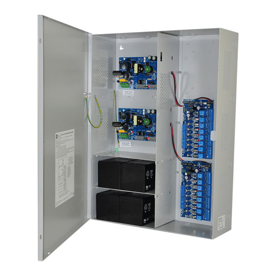
Access Power Controllers with
Power Supplies
Installation Guide
Models Include:
Maximal11FV
- Power Supply 1:
12VDC @ 3.3A or 24VDC @ 3.6A.
- Power Supply 2:
12VDC @ 3.3A or 24VDC @ 3.6A.
- Sixteen (16) fuse protected outputs.
Maximal33FV
- Power Supply 1:
12VDC @ 5.3A or 24VDC @ 5.6A.
- Power Supply 2:
12VDC @ 5.3A or 24VDC @ 5.6A.
- Sixteen (16) fuse protected outputs.
Rev. DFFV031115
Installing Company: ________________ Service Rep. Name: ______________________________________
Address: ___________________________________________________ Phone #: _____________________
Maximal55FV
- Power Supply 1: 12VDC @ 9.3A.
- Power Supply 2: 12VDC @ 9.3A.
- Sixteen (16) fuse protected outputs.
Maximal77FV
- Power Supply 1: 24VDC @ 9.6A.
- Power Supply 2: 24VDC @ 9.6A.
- Sixteen (16) fuse protected outputs.
Maximal75FV
- Power Supply 1: 12VDC @ 9.3A.
- Power Supply 2: 24VDC @ 9.6A.
- Sixteen (16) fuse protected outputs.
More than just power.
TM
Advertisement
Table of Contents

Subscribe to Our Youtube Channel
Related Manuals for Altronix Maximal


Summary of Contents for Altronix Maximal
- Page 1 Access Power Controllers with Power Supplies Installation Guide Models Include: Maximal11FV Maximal55FV - Power Supply 1: - Power Supply 1: 12VDC @ 9.3A. 12VDC @ 3.3A or 24VDC @ 3.6A. - Power Supply 2: 12VDC @ 9.3A. - Power Supply 2: - Sixteen (16) fuse protected outputs.
-
Page 2: Table Of Contents
Maximal Series Features ........ -
Page 3: Maximalfv Series Overview
MaximalFV Series Overview: Altronix MaximalFV Access Power/Controllers distribute and switch power to access control systems and acces- sories. They convert a 220VAC (working range 198VAC - 256VAC), 50/60Hz input into sixteen (16) indepen- dently controlled 12VDC or 24VDC fuse protected outputs. These Fail-Safe/Fail-Secure power outputs may be converted to dry form “C”... -
Page 4: Agency Listings
MaximalFV Series Features: ACM8 Access Power Controller Modules: • Sixteen (16) independently trigger controlled outputs. Output options: a) Sixteen (16) Fail-Safe filtered power outputs. b) Sixteen (16) Fail-Secure filtered power outputs. c) Sixteen (16) form “C” relay outputs (rated @ 5A/28VDC or VAC). d) Any combination of the above. -
Page 5: Maximalfv Installation Instructions
MaximalFV Installation Instructions: Wiring methods shall be in accordance with the National Electrical Code/NFPA 70/ANSI, the Canadian Electric Code, Part I, Part II and with all local codes and authorities having jurisdiction. Product is intended for indoor use only. Power Supply Board LED Diagnostics (pg. -
Page 6: Maintenance
(a) Normally Open [NO] input: For non-latching hook-up refer to Fig. 6, pg. 12. For latching hook-up refer to Fig. 7, pg. 12. (b) Normally Closed [NC] input: For non-latching hook-up refer to Fig. 8, pg. 12. For latching hook-up refer to Fig. 9, pg. 12. (c) FACP Signaling Circuit input trigger: Connect the positive (+) and negative (–) from the FACP signaling circuit output to the terminals marked [+ INP –]. -
Page 7: Power Supply Board Led Diagnostics
Power Supply Board LED Diagnostics: Red (DC) Green (AC/AC1) Power Supply Status Normal operating condition. Loss of AC. Stand-by battery supplying power. No DC output. Loss of AC. Discharged or no stand-by battery. No DC output. Red (Bat) Battery Status Normal operating condition. -
Page 8: Access Power Controller Terminal Identification
Access Power Controller Terminal Identification: Terminal Legend Function/Description 12VDC or 24VDC from power supply/charger (factory connected). – Power + These terminals are paralleled to the [– Control +] terminals. These terminals are paralleled to the [– Power +] terminals. These terminals can be connected to an external Listed power-limited access control power supply to provide –... -
Page 9: Power Supply Board Output Voltage Settings
Power Supply Board Output Voltage Settings: Fig. 1 Fig. 1a OFF - 24V ON - 12V OFF - 24V ON - 12V Access Power Controller Typical Application Diagram (for each ACM8): Fig. 2 Fig. 2a Intact = Dry Input Normally Open (N.O.) Cut = Wet Input Door Releasing FACP... -
Page 10: Maximalfv Battery Hookup And Tamper Switch Installation
Fig. 3 Tamper Switch Power Supply Board AC FAIL BAT FAIL AC DELAY SHUTDOWN 5A 250V 1 min. enable TRIGGER EOL NC C NO NC C NO + AUX – 2 hr. disable SUPERVISED RESET Line Neutral Wire Strap (from Power Supply Board Enclosure to Door) -
Page 11: Nec Power-Limited Wiring Requirements
NEC Power-Limited Wiring Requirements: Power-limited and non power-limited circuit wiring must remain separated in the cabinet. All power-limited circuit wiring must remain at least 0.25” away from any non power-limited circuit wiring. Furthermore, all power-limited circuit wiring and non power-limited circuit wiring must enter and exit the cabinet through differ- ent conduits. -
Page 12: Facp/Optional Power Supply Hook-Up Diagrams
FACP Hook-Up Diagrams: Fig. 5 Optional hook-up using two (2) isolated Fig. 6 Polarity reversal input from FACP power supply inputs (Only applicable on signaling circuit output (polarity is Maximal11FV): referenced in alarm condition): CUT JUMPERS JUMPER J1 AND J2 FACP FACP OUTPUT EOL... - Page 13 Notes: Maximal11FV / Maximal33FV / Maximal55FV / Maximal77FV / Maximal75FV Access Power Controllers (Fused) - 13 -...
- Page 14 Notes: - 14 - Maximal11FV / Maximal33FV / Maximal55FV / Maximal77FV / Maximal75FV Access Power Controllers (Fused)
-
Page 15: Enclosure Dimensions
19” (482.6mm) Altronix is not responsible for any typographical errors. 140 58th Street, Brooklyn, New York 11220 USA | phone: 718-567-8181 | fax: 718-567-9056 website: www.altronix.com | e-mail: info@altronix.com | Lifetime Warranty | Made in U.S.A. MEMBER IIMaximal11FV/33FV/55FV/75FV/77FV Series G30R... - Page 16 - UL Listed in the U.S. and Canada. - Local or remote control of up to (2) two Altronix eFlow power output(s) via LAN and/or WAN. - Monitor real time diagnostics: DC output voltage, output current, AC & battery status/service, input trigger state change, output state change and unit temperature.
Need help?
Do you have a question about the Maximal and is the answer not in the manual?
Questions and answers