Table of Contents
Advertisement
Quick Links
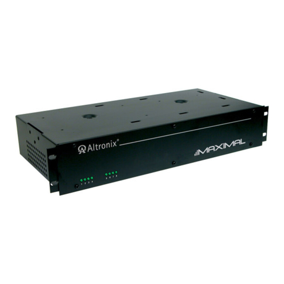
Maximal R Series
Rack Mount Access Power Controllers (fused)
Models Include:
Maximal1RH
- 12VDC @ 4A or 24VDC @ 3A.
- Eight (8) fuse protected outputs.
Maximal3RH
- 12VDC or 24VDC @ 6A.
- Eight (8) fuse protected outputs.
Maximal33R
- 12VDC or 24VDC @ 12A.
- Sixteen (16) fuse protected outputs.
Installation Guide
Rev. 090109
Installing Company: _______________ Service Rep. Name: __________________________________
Address: _____________________________________________ Phone #: __________________
Maximal1R
- 12VDC @ 4A or 24VDC @ 3A.
- Sixteen (16) fuse protected outputs.
Maximal3R
- 12VDC or 24VDC @ 6A.
- Sixteen (16)) fuse protected outputs.
More than just power.
TM
Advertisement
Table of Contents

Related Manuals for Altronix Maximal R Series


Summary of Contents for Altronix Maximal R Series
- Page 1 Maximal R Series Rack Mount Access Power Controllers (fused) Models Include: Maximal1RH Maximal1R - 12VDC @ 4A or 24VDC @ 3A. - 12VDC @ 4A or 24VDC @ 3A. - Eight (8) fuse protected outputs. - Sixteen (16) fuse protected outputs.
-
Page 2: Table Of Contents
Table of Contents: Overview ..............pg. 3 Maximal Rack Mount Series Configuration Chart . -
Page 3: Overview
Overview: Altronix Maximal Rack Mount Series units distribute and switch power to access control systems and accessories. They convert a 115VAC, 50/60Hz input into eight (8) or sixteen (16) independently controlled 12VDC and/or 24VDC fuse protected outputs. Outputs are activated by a normally open (NO) or normally closed (NC) dry trigger input from an Access Control System, Card Reader, Keypad, Push Button, PIR, etc. -
Page 4: Installation Instructions
Installation Instructions: Important: Adjust output voltages and Fire Alarm Interface configuration before installing unit in the rack. 1. Separate bottom and top of the rack mount chassis by removing six (6) screws (Rack Mechanical Drawing and Dimensions, pg. 12). CAUTION: Do not touch exposed metal parts. Shut branch circuit power before installing or servicing equipment. -
Page 5: Maintenance
FACP Signal Circuit (Polarity Reversal). Normally Closed [NC] Trigger Input. Normally Open [NO] Trigger Input. Output Voltage and Stand-by Specification Charts: 20 Min. of 4 Hr. of 24 Hr. of Altronix Model Power Supply Board Battery Backup Backup Backup OLS120 12VDC/40AH* 3.5A... -
Page 6: Power Supply Board Output Voltage Settings
WARNING: To reduce the risk of fire or electric shock, do not expose the unit to rain or moisture. This installation should be made by qualified service personnel and should conform to the National Electrical Code and all local codes. The lightning flash with arrowhead symbol within an equilateral triangle is intended to alert the user to the presence of an insulated DANGEROUS VOLTAGE within the product’s enclosure that may be of sufficient magnitude to constitute an electric shock. -
Page 7: Fire Alarm Interface, Output Selection, And Input Type
Fire Alarm Interface, Output Selection, and Input Type: Fig. 2 Output Trigger LEDs FIRE ALARM INTERFACE OUTPUT SELECT ACM8R-S Fig. 2a Fig. 2b OFF - NC Input ON - NO Input DIP Switches for FACP and Output DIP Switch for Programming NO or NC Input Output Trigger LEDs... -
Page 8: Power Supply Boards Drawings
Power Supply Board Maximal1RH, Maximal1R Fig. 4 Power Supply Board AC DC 5A 250V C NO NC C – BAT + – DC + Fig. 4a Fig. 4b --- BAT – BAT + C NO NC C Battery and Built-in Built-in AC Supervision Battery Charging... -
Page 9: Facp Hook-Up Diagrams
FACP Hook-Up Diagrams Polarity Reversal Input from FACP Signal Circuit Output (Polarity is referenced in alarm condition) Fig. 6 Fig. 7 5-30VDC 5-30VDC from FACP from FACP FACP FACP Signal Circuit Signal Circuit RESET Normally Open [NO] Factory Installed RESET Jumper Reset Switch Non-Latching... -
Page 10: Mounting Options
Mounting Options: Mounting Hardware Fig. 12 (Included): Two (2) mounting brackets. Eight (8) flat head screws for mounting brackets. Remove center brace Eight (8) pan head screws from rack mount chassis for faceplate. before proceeding with installation. Rack Mount Installation 1. - Page 11 Notes: Maximal Rack Access Power Controllers (Fused) Installation Guide - 11 -...
-
Page 12: Rack Mechanical Drawing And Dimensions
Top and Bottom Front 19.125" (485.8mm) 0.75" (19.1mm) Altronix is not responsible for any typographical errors. –––––––––––––––––––––––––––––––––––––––––––––––––––––––––––––––––––––––––––––––––––––––––––––––––––––––––––––––– 140 58th Street, Brooklyn, New York 11220 USA | phone: 718-567-8181 | fax: 718-567-9056 website: www.altronix.com | e-mail: info@altronix.com | Lifetime Warranty IIMaximal Rack Mount Series...
Need help?
Do you have a question about the Maximal R Series and is the answer not in the manual?
Questions and answers