Table of Contents
Advertisement
Quick Links
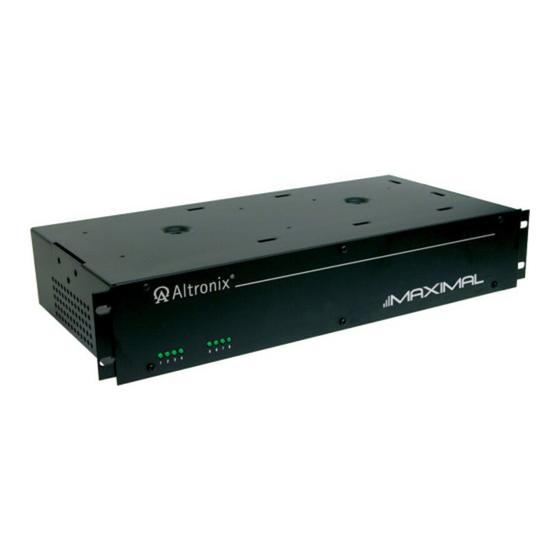
Rack Mount Series
Installation Guide
Models Include:
Maximal1RHV
- 12VDC @ 4A or 24VDC @ 3A.
- Eight (8) Fuse Protected Outputs.
Maximal3RHV
- 12VDC or 24VDC @ 6A.
- Eight (8) Fuse Protected Outputs.
Maximal33RV
- 12VDC and/or 24VDC @ 12A.
- Sixteen (16) Fuse Protected Outputs.
Rev. 090109
Maximal1RV
- 12VDC @ 4A or 24VDC @ 3A.
- Sixteen (16) Fuse Protected Outputs.
Maximal3RV
- 12VDC or 24VDC @ 6A.
- Sixteen (16) Fuse Protected Outputs.
More than just power.
TM
Advertisement
Table of Contents

Related Manuals for Altronix Maximal1RHV


Summary of Contents for Altronix Maximal1RHV
- Page 1 Rack Mount Series Installation Guide Models Include: Maximal1RHV Maximal1RV - 12VDC @ 4A or 24VDC @ 3A. - 12VDC @ 4A or 24VDC @ 3A. - Eight (8) Fuse Protected Outputs. - Sixteen (16) Fuse Protected Outputs. Maximal3RHV Maximal3RV - 12VDC or 24VDC @ 6A.
-
Page 2: Table Of Contents
Table of Contents: Maximal Rack Mount Series Overview ................3 Maximal Rack Mount Series Configuration Chart ............3 Maximal Rack Mount Series Specifications ..............3 Installation Instructions ....................4 Maintenance ........................5 Fire Alarm Interface Switch Settings ................5 Output Voltage and Stand-by Specification Charts ............5 LED Diagnostics ...................... -
Page 3: Maximal Rack Mount Series Overview
ACM8R-M (current Board Input Model Number (8 outputs) (8 outputs) Current Outputs Output draw) Fuse Rating 12VDC @ 4A Maximal1RHV 2.5A 0.9A 5A/250V 24VDC @ 3A 12VDC @ 4A Maximal1RV 2.5A 0.9A 5A/250V 24VDC @ 3A 12VDC @ 6A Maximal3RHV 2.5A... -
Page 4: Installation Instructions
Make sure the devices match settings of SW3 in step 3 (Rack Mechanical Drawing and Dimensions pg. 11). 17. Output connections: Connect the devices to be powered to the removable terminals marked [-- OUT1 + to -- OUT8 +] for Maximal1RHV and Maximal3RHV. For Maximal1RV, Maximal3RV and Maximal33RV connect devices to the second set of terminals marked [-- OUT1 + to -- OUT8 +] (Fig. -
Page 5: Maintenance
FACP Signal Circuit (Polarity Reversal). Normally Closed [NC] Trigger Input. Normally Open [NO] Trigger Input. Output Voltage and Stand-by Specification Charts: 20 Min. of 4 Hr. of 24 Hr. of Altronix Model Power Supply Board Battery Backup Backup Backup 12VDC/40AH* 3.5A... -
Page 6: Power Supply Board Output Voltage Settings
Power Supply Board Output Voltage Settings: Fig. 1 Fig. 1a Power Supply Board OFF - 24V ON - 12V OFF - 24V ON - 12V Fire Alarm Interface, Output Selection and Input Type: Fig. 2 Output Trigger LEDs FIRE ALARM INTERFACE OUTPUT SELECT ACM8R-S Fig. - Page 7 Fig. 3 Fig. 3a Fig. 3b Fig. 3c FIRE ALARM RESET DIP Switch for DIP Switch for Selecting type of Selecting type of FACP Input FACP Input ACM8R-M FIRE ALARM RESET Maximal Rack Access Power Controllers (Fused) - 7 -...
-
Page 8: Power Supply Board Drawings
Power Supply Board Fig. 4 Power Supply Board AC DC 5A 250V C NO NC C --- BAT + --- DC + Fig. 4a Fig. 4b --- BAT --- BAT C NO NC C Battery and AC Supervision Built-in Built-in Battery Charging Battery Charging - 8 -... -
Page 9: Facp Hook-Up Diagrams
FACP Hook-Up Diagrams Polarity Reversal Input from FACP Signal Circuit Output (Polarity is referenced in alarm condition) Fig. 5 Fig. 6 5-30VDC 5-30VDC from FACP from FACP FACP FACP Signal Circuit Signal Circuit RESET Factory Installed Normally Open [NO] RESET Reset Switch Jumper Non-Latching... -
Page 10: Mounting Bracket Diagrams
Mounting Options: Fig. 11 Mounting Hardware (Included): Two (2) mounting brackets. Eight (8) flat head screws for mounting brackets. Remove center brace from rack mount chassis Eight (8) pan head screws for faceplate. before proceeding with installation. Rack Mount Installation 1. -
Page 11: Rack Mechanical Drawing And Dimensions
Rack Mechanical Drawing and Dimensions 3.25” x 19.125” x 8.5” (82.55mm x 485.78mm x 215.9mm) Fig. 14 Fig. 14a Fig. 14b Fig. 14c (ON) 3-Wire Line Cord Removable Terminal Block Rear Terminal Legend 3.125" 79.4mm Bottom 17.625" 447.7mm 8.5" 215.9mm Front 19.125"... - Page 12 Notes: Altronix is not responsible for any typographical errors. 140 58th Street, Brooklyn, New York 11220 USA, 718-567-8181, fax: 718-567-9056 web site: www.altronix.com, e-mail: info@altronix.com. Lifetime Warranty, Made in U.S.A. IIMaximalRackMountSeries A27P MEMBER - 12 - Maximal Rack Access Power Controllers (Fused)
Need help?
Do you have a question about the Maximal1RHV and is the answer not in the manual?
Questions and answers