Table of Contents
Advertisement
Quick Links
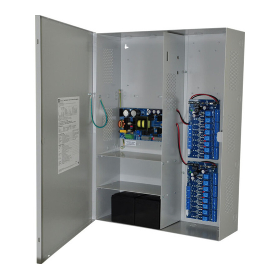
Maximal FD Series
Single Power Supply
Access Power Controllers (PTC)
Models Include:
Maximal3FD
- 12VDC @ 4.6A or 24VDC @ 5.2A.
- Sixteen (16) PTC protected power-limited outputs.
Maximal5FD
- 12VDC @ 8.6A.
- Sixteen (16) PTC protected power-limited outputs.
Maximal7FD
- 24VDC @ 9.2A.
- Sixteen (16) PTC protected power-limited outputs.
Installation Guide
Rev. MSFD052419
Installing Company: _______________ Service Rep. Name: __________________________________
Address: _____________________________________________ Phone #: __________________
Altronix Corp.
140 58th St. Brooklyn, NY
More than just power.
TM
Advertisement
Table of Contents

Related Manuals for Altronix Maximal FD Series


Summary of Contents for Altronix Maximal FD Series
- Page 1 Maximal FD Series Single Power Supply Access Power Controllers (PTC) Models Include: Maximal3FD - 12VDC @ 4.6A or 24VDC @ 5.2A. - Sixteen (16) PTC protected power-limited outputs. Maximal5FD - 12VDC @ 8.6A. - Sixteen (16) PTC protected power-limited outputs.
-
Page 2: Table Of Contents
Table of Contents: MaximalFD Series Overview ..........pg. 3 MaximalFD Series Configuration Chart . -
Page 3: Maximalfd Series Overview
MaximalFD Series Overview: Altronix MaximalFD Access Power/Controllers distribute and switch power to access control systems and accessories. They convert a 120VAC 60Hz input into sixteen (16) independently controlled 12VDC or 24VDC PTC protected protected outputs. The outputs are activated by an open collector sink or normally open (NO) dry trigger input from an Access Control System, Keypad, Push Button, REX PIR, etc. -
Page 4: Maximal Series Features
MaximalFD Series Features: ACM8CB Access Power Controller Modules: • Sixteen (16) independently trigger controlled outputs. Output options: a) Sixteen (16) Fail-Safe filtered power outputs. b) Sixteen (16) Fail-Secure filtered power outputs. c) Any combination of the above. • Sixteen (16) Access Control System trigger inputs. Input trigger options: a) Sixteen (16) normally open (NO) dry trigger inputs. -
Page 5: Maximalfd Installation Instructions
MaximalFD Installation Instructions: Wiring methods shall be in accordance with the National Electrical Code/NFPA 70/ANSI, the Canadian Electric Code, Part I, Part II and with all local codes and authorities having jurisdiction. Product is intended for indoor use only. Power Supply Board LED Diagnostics (pg. - Page 6 14. Installation of Tamper Switch (Fig. 3b, pg. 10): Mount UL Listed tamper switch (Altronix model TS112 or equivalent) at the top of the enclosure. Slide the tamper switch bracket onto the edge of the enclosure approximately 2” from the right side (Fig. 3b, pg. 10).
-
Page 7: Maintenance
Maintenance: Unit should be tested at least once a year for the proper operation as follows: FACP Supervision: To ensure proper connection and operation of the Fire Alarm disconnect hookup, please follow the appropriate procedure below: Normally Open Input: Placing a short between terminals marked [T] and [+ INP] will trigger the Fire Alarm Disconnect. -
Page 8: Power Supply Board Terminal Identification
Power Supply Board Terminal Identification: Terminal Legend Function/Description Connect 120VAC 60Hz to these terminals: L to hot, N to neutral. L, G, N Do not use terminal marked [G]. + DC – Factory connected to ACM8CB boards. Fire Alarm Interface trigger input from a short or FACP. Trigger inputs can be normally Trigger EOL open, normally closed from an FACP output circuit (Class 2 power-limited input) Supervised... -
Page 9: Power Supply Board Output Voltage Settings
Power Supply Board Output Voltage Settings: Fig. 1 Fig. 1a OFF - 24V ON - 12V OFF - 24V ON - 12V Access Power Controller Typical Application Diagram (for each ACM8CB): Fig. 2 Fig. 2a Intact = Dry Input Normally Open (N.O.) Cut = Wet Input Door Releasing FACP... -
Page 10: Maximalfd Battery Hookup And Tamper Switch Installation
Fig. 3 - Maximal3FD, Maximal5FD, and Maximal7FD Tamper Switch Earth Ground OFF - 24V ON - 12V Power Supply Board AC DC NC C NO NC C NO TRIGGER +AUX- AC FAIL BAT FAIL SUPERVISED RESET Line Neutral Input 120VAC, 60Hz CAUTION: When power supply board is set for 12VDC Fig. -
Page 11: Nec Power-Limited Wiring Requirements
NEC Power-Limited Wiring Requirements: Power-limited and non power-limited circuit wiring must remain separated in the cabinet. All power-limited circuit wiring must remain at least 0.25” away from any non power-limited circuit wiring. Furthermore, all power-limited circuit wiring and non power-limited circuit wiring must enter and exit the cabinet through different conduits. One such example of this is shown below. -
Page 12: Facp/Optional Power Supply Hook-Up Diagrams
FACP Hook-Up Diagrams: Fig. 5 Polarity reversal input from FACP signaling circuit output (polarity is referenced in alarm condition): JUMPER FACP FACP OUTPUT EOL FROM FACP OUTPUT CIRCUIT Fig. 6 Normally Open: Non-Latching FACP Fig. 7 Normally Open FACP Latching trigger trigger input: input with reset (This output has not been evaluated by UL):... - Page 13 Notes: Maximal3FD/5FD/7FD Series (PTC) Installation Guide - 13 -...
- Page 14 Notes: - 14 - Maximal3FD/5FD/7FD Series (PTC) Installation Guide...
-
Page 15: Enclosure Dimensions
(21.6mm) (21.6mm) 4” (101.6mm) 2” (50.8mm) 19” (482.6mm) Altronix is not responsible for any typographical errors. –––––––––––––––––––––––––––––––––––––––––––––––––––––––––––––––––––––––––––––––––––––––––––––––––––––––––––––––– 140 58th Street, Brooklyn, New York 11220 USA | phone: 718-567-8181 | fax: 718-567-9056 website: www.altronix.com | e-mail: info@altronix.com | Lifetime Warranty MEMBER... - Page 16 - UL Listed in the U.S. and Canada. - Local or remote control of up to (2) two Altronix eFlow power output(s) via LAN and/or WAN. - Monitor real time diagnostics: DC output voltage, output current, AC & battery status/service, input trigger state change, output state change and unit temperature.
Need help?
Do you have a question about the Maximal FD Series and is the answer not in the manual?
Questions and answers