Table of Contents
Advertisement
Quick Links
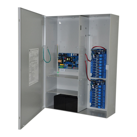
Access Power Controllers
Installation Guide
Models Include:
Maximal3D
- 12VDC @ 5A or 24VDC @ 5.4A.
- Sixteen (16) PTC protected Class 2 Rated power-limited outputs.
Maximal5D
- 12VDC @ 9A.
- Sixteen (16) PTC protected Class 2 Rated power-limited outputs.
Maximal7D
- 24VDC @ 9.4A.
- Sixteen (16) PTC protected Class 2 Rated power-limited outputs.
Rev. SCB110912
Altronix Corp.
140 58th St. Brooklyn, NY
More than just power.
TM
Advertisement
Table of Contents

Related Manuals for Altronix MaximalD Series


Summary of Contents for Altronix MaximalD Series
- Page 1 - 12VDC @ 9A. - Sixteen (16) PTC protected Class 2 Rated power-limited outputs. Maximal7D - 24VDC @ 9.4A. - Sixteen (16) PTC protected Class 2 Rated power-limited outputs. Altronix Corp. 140 58th St. Brooklyn, NY More than just power. Rev. SCB110912...
-
Page 2: Table Of Contents
Table of Contents: MaximalD Series Overview pg. 3 . . . . . . . . . . . . . . . . . . . . . . . . . . . . . . . . . . . . . . . . . . . . . . . . . . . . . . . . . . . . . . . . . . . . . . . . . . . . -
Page 3: Maximald Series Overview
Emergency Egress, Alarm Monitoring, or may be used to trigger other auxiliary devices . The fire alarm disconnect feature is individually selectable for any or all of the sixteen (16) outputs . All interconnecting equip- ment must be UL Listed . MaximalD Series Configuration Chart: Altronix Power Supply... -
Page 4: Maximald Installation Instructions
MaximalD Installation Instructions: Wiring methods shall be in accordance with the National Electrical Code/NFPA 70/ANSI, and with all local codes and authorities having jurisdiction . Product is intended for indoor use only . Power Supply Board LED Diagnostics (pg. 5) Access Power Controller LED Diagnostics (pg. -
Page 5: Maintenance
10 . Stand-by Battery Connections (Figs. 3-7, pgs. 8-12): For Access Control applications batteries are optional . If batteries are not used a loss of AC will result in the loss of output voltage . Batteries must be lead acid or gel type . Connect one (1) 12VDC battery to the terminals marked [+ BAT –] for 12VDC operation (Fig. -
Page 6: Access Power Controller Led Diagnostics
FACP signaling circuit output (Figs. 8-12, pgs. 13-14). FACP INTERFACE Form “C” relay contact rated @ 1A/28VDC for alarm reporting (not evaluated by UL) . NC, C, NO Power Supply Board Stand-by Battery Specifications: Altronix 20 Min. of 4 hr. of 24 hr. of Power Supply Board... -
Page 7: Power Supply Board Output Voltage Settings
Power Supply Board Output Voltage Settings: Fig. 1a - Maximal3D Power Supply Board OFF - 24V Fig. 1b ON - 12V OFF - 24V ON - 12V Access Power Controller Typical Application Diagram (for each ACM8CB): Fig. 2 Fig. 2a Intact = Dry Input Normally Open (N.O.) Cut = Wet Input... -
Page 8: Maximal3D And Maximal5D Battery Hookup And Tamper Switch Installation
Fig. 3 - Maximal3D and Maximal5D Tamper Switch Maximal5D Wire Strap (from Enclosure to Door) Power Supply Board BAT FAIL AC FAIL Input NO C NC NO C NC Line 115VAC, Neutral Earth Ground 60 Hz. *12VDC operation: For 12VDC operation only a single battery is needed. Connect red battery lead to terminal marked [+ BAT] and to the [positive (+)] terminal of the... -
Page 9: Maximal7D Battery Hookup And Tamper Switch Installation
Fig. 4 - Maximal7D Tamper Switch Power Supply Board BAT FAIL AC FAIL Input NC C NO NC C NO AC DELAY Line Neutral 115VAC, Earth Ground 60 Hz. 12VDC Rechargeable 12VDC Rechargeable Battery** Battery** (Optional) (Optional) **24VDC operation: Connect two (2) 12VDC batteries in series Fig. -
Page 10: Nec Power-Limited Wiring Requirements For Maximal3D
NEC Power-Limited Wiring Requirements for Maximal3D: Power-limited and non power-limited circuit wiring must remain separated in the cabinet . All power-limited circuit wiring must remain at least 0 .25” away from any non power-limited circuit wiring . Furthermore, all power-limited circuit wiring and non power-limited circuit wiring must enter and exit the cabinet through differ- ent conduits . -
Page 11: Nec Power-Limited Wiring Requirements For Maximal5D
NEC Power-Limited Wiring Requirements for Maximal5D: Power-limited and non power-limited circuit wiring must remain separated in the cabinet . All power-limited circuit wiring must remain at least 0 .25” away from any non power-limited circuit wiring . Furthermore, all power-limited circuit wiring and non power-limited circuit wiring must enter and exit the cabinet through differ- ent conduits . -
Page 12: Nec Power-Limited Wiring Requirements For Maximal7D
NEC Power-Limited Wiring Requirements for Maximal7D: Power-limited and non power-limited circuit wiring must remain separated in the cabinet . All power-limited circuit wiring must remain at least 0 .25” away from any non power-limited circuit wiring . Furthermore, all power-limited circuit wiring and non power-limited circuit wiring must enter and exit the cabinet through differ- ent conduits . -
Page 13: Facp Hook-Up Diagrams
FACP Hook-Up Diagrams: Fig. 8 Polarity reversal input from FACP signaling circuit output (polarity is referenced in alarm condition): JUMPER FACP OUTPUT EOL FROM FACP OUTPUT CIRCUIT Fig. 9 Normally Open - Non-Latching FACP trigger input: N.O. TRIGGER INPUT Fig. 10 Normally Open FACP Latching trigger input with reset (This output has not been evaluated by UL): N.O. - Page 14 FACP Hook-Up Diagrams (cont’d): Fig. 11 Normally Closed - Non-Latching FACP trigger input: N.C. DRY TRIGGER INPUT JUMPER Fig. 12 Normally Closed - Latching FACP trigger input with reset (This output has not been evaluated by UL): N.C. RESET SWITCH N.C.
- Page 15 Notes: Maximal3D/Maximal5D/Maximal7D Access Power Controllers (PTC) - 15 -...
-
Page 16: Enclosure Dimensions
Altronix is not responsible for any typographical errors . 140 58th Street, Brooklyn, New York 11220 USA | phone: 718-567-8181 | fax: 718-567-9056 website: www .altronix .com | e-mail: info@altronix .com | Lifetime Warranty | Made in U .S .A . MEMBER...
Need help?
Do you have a question about the MaximalD Series and is the answer not in the manual?
Questions and answers