Table of Contents
Advertisement
Quick Links
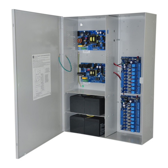
Access Power Controllers
Installation Guide
Models Include:
Maximal11V
- Power Supply 1:
12VDC @ 3.5A or 24VDC @ 2.7A.
- Power Supply 2:
12VDC @ 3.5A or 24VDC @ 2.7A.
- Sixteen (16) fuse protected outputs.
Maximal33V
- Power Supply 1:
12VDC @ 5.5A or 24VDC @ 5.7A.
- Power Supply 2:
12VDC @ 5.5A or 24VDC @ 5.7A.
- Sixteen (16) fuse protected outputs.
Rev. DFV081011
Maximal55V
- Power Supply 1: 12VDC @ 9.5A.
- Power Supply 2: 12VDC @ 9.5A.
- Sixteen (16) fuse protected outputs.
Maximal77V
- Power Supply 1: 24VDC @ 9.7A.
- Power Supply 2: 24VDC @ 9.7A.
- Sixteen (16) fuse protected outputs.
Maximal75V
- Power Supply 1: 12VDC @ 9.5A.
- Power Supply 2: 24VDC @ 9.7A.
- Sixteen (16) fuse protected outputs.
More than just power.
TM
Advertisement
Table of Contents

Related Manuals for Altronix MaximalV Series


Summary of Contents for Altronix MaximalV Series
- Page 1 Access Power Controllers Installation Guide Models Include: Maximal11V Maximal55V - Power Supply 1: - Power Supply 1: 12VDC @ 9.5A. 12VDC @ 3.5A or 24VDC @ 2.7A. - Power Supply 2: 12VDC @ 9.5A. - Power Supply 2: - Sixteen (16) fuse protected outputs. 12VDC @ 3.5A or 24VDC @ 2.7A.
-
Page 2: Table Of Contents
Table of Contents: MaximalV Series Overview pg. 3 . . . . . . . . . . . . . . . . . . . . . . . . . . . . . . . . . . . . . . . . . . . . . . . . . . . . . . . . . . . . . . . . . . . . . . . . . . . . -
Page 3: Maximalv Series Overview
MaximalV Series Overview: Altronix MaximalV Access Power/Controllers distribute and switch power to access control systems and acces- sories . They convert a 220VAC (working range 198VAC - 256VAC), 50/60Hz input into sixteen (16) indepen- dently controlled 12VDC or 24VDC fuse protected outputs . These Fail-Safe/Fail-Secure power outputs may be converted to dry form “C”... -
Page 4: Maximalv Installation Instructions
• ACM8 board main fuses are rated @ 10A . Output fuses are rated @ 3 .5A . • Built-in charger for sealed lead acid or gel type batteries . - Maximum charge current is 0 .7A for AL400XB2V, AL600XB220 and AL1012XB220 power supply boards . - Maximum charge current is 3 .6A for AL1024XB2V power supply board . - Page 5 7 . Input trigger options (Fig. 2, pg. 9): (a) Normally Open [NO] input trigger: Inputs 1-8 are activated by normally open or open collector sink inputs . Connect access control panel outputs, keypads, push buttons, REX PIRs, etc . to the terminals marked [IN] and [GND] .
-
Page 6: Maintenance
Maintenance: Unit should be tested at least once a year for the proper operation as follows: FACP Supervision: To ensure proper connection and operation of the Fire Alarm disconnect hookup . Please follow the appropriate procedure below: Normally Open Input: Placing a short between terminals marked [T] and [+ INP] will trigger the Fire Alarm Disconnect . -
Page 7: Power Supply Board Terminal Identification
Power Supply Board Terminal Identification: Terminal Legend Function/Description L, N Connect 220VAC, 50/60Hz to these terminals: L to hot, N to neutral . Maximal11V - 12VDC @ 3 .5A or 24VDC @ 2 .7A to ACM8 boards . Maximal33V - 12VDC @ 5 .5A or 24VDC @ 5 .7A to ACM8 boards . Maximal55V - 12VDC @ 9 .5A to ACM8 boards . -
Page 8: Power Supply Board Stand-By Battery Specifications
Power Supply Board Stand-by Battery Specifications: Altronix 20 Min. of 24 Hr. of Power Supply Board Battery 4 Hr. of Backup Model Backup Backup 12VDC/ AL400XB2V 3 .5A 0 .5A 40AH* (Refer to Fig. 1a, pg. 9 Maximal11 for Switch [SW1] 24VDC/ 2 .7A... -
Page 9: Power Supply Board Output Voltage Settings
Power Supply Board Output Voltage Settings: Fig. 1a - Maximal11V and Maximal33V Power Supply Board OFF - 24V Fig. 1b ON - 12V OFF - 24V ON - 12V Access Power Controller Typical Application Diagram (for each ACM8): Fig. 2 Fig. -
Page 10: Maximal11V, Maximal33V, Maximal55V
Fig. 3 - Maximal11V, Maximal33V, Maximal55V Tamper Switch Power Supply Board BAT FAIL AC FAIL NC C NO NC C NO Line Neutral Wire Strap (from Power Supply Board Enclosure to Door) BAT FAIL AC FAIL Input NC C NO NC C NO Line Neutral... -
Page 11: Maximal77V Battery Hookup And Tamper Switch Installation
Fig. 4 - Maximal77V Tamper Switch Power Supply Board BAT FAIL AC FAIL NC C NO NC C NO Line Neutral Wire Strap (from Power Supply Board Enclosure to Door) Input BAT FAIL AC FAIL NC C NO NC C NO 220VAC, Line Neutral... -
Page 12: Maximal75V Battery Hookup And Tamper Switch Installation
Fig. 5 - Maximal75V Tamper Switch Power Supply Board BAT FAIL AC FAIL NC C NO NC C NO Line Neutral Wire Strap (from Enclosure Power Supply Board to Door) BAT FAIL AC FAIL Input NC C NO NC C NO Line Neutral 220VAC,... -
Page 13: Nec Power-Limited Wiring Requirements For Maximal11V
NEC Power-Limited Wiring Requirements for Maximal11V: Power-limited and non power-limited circuit wiring must remain separated in the cabinet . All power-limited circuit wiring must remain at least 0 .25” away from any non power-limited circuit wiring . Furthermore, all power-limited circuit wiring and non power-limited circuit wiring must enter and exit the cabinet through differ- ent conduits . -
Page 14: Nec Power-Limited Wiring Requirements For Maximal33V And Maximal55V
NEC Power-Limited Wiring Requirements for Maximal33V and Maximal55V: Power-limited and non power-limited circuit wiring must remain separated in the cabinet . All power-limited circuit wiring must remain at least 0 .25” away from any non power-limited circuit wiring . Furthermore, all power-limited circuit wiring and non power-limited circuit wiring must enter and exit the cabinet through differ- ent conduits . -
Page 15: Nec Power-Limited Wiring Requirements For Maximal77V
NEC Power-Limited Wiring Requirements for Maximal77V: Power-limited and non power-limited circuit wiring must remain separated in the cabinet . All power-limited circuit wiring must remain at least 0 .25” away from any non power-limited circuit wiring . Furthermore, all power-limited circuit wiring and non power-limited circuit wiring must enter and exit the cabinet through differ- ent conduits . -
Page 16: Nec Power-Limited Wiring Requirements For Maximal75V
NEC Power-Limited Wiring Requirements for Maximal75V: Power-limited and non power-limited circuit wiring must remain separated in the cabinet . All power-limited circuit wiring must remain at least 0 .25” away from any non power-limited circuit wiring . Furthermore, all power-limited circuit wiring and non power-limited circuit wiring must enter and exit the cabinet through differ- ent conduits . -
Page 17: Facp/Optional Power Supply Hook-Up Diagrams
FACP/Optional Power Supply Hook-up Diagrams: Fig. 10 Optional hook-up using two (2) isolated power supply inputs (Only applicable on Maximal11V): CUT JUMPERS J1 AND J2 ISOLATED POWER INPUT 12 OR 24 VAC OR VDC (ACM8 POWER) ISOLATED POWER INPUT 12 OR 24 VAC OR VDC (LOCK POWER) Fig. - Page 18 FACP/Optional Power Supply Hook-up Diagrams (cont’d): Fig. 13 Normally Open FACP Latching trigger input with reset: N.O. TRIGGER INPUT N.C. RESET SWITCH JUMPER Fig. 14 Normally Closed - Non-Latching FACP trigger input: N.C. DRY TRIGGER INPUT JUMPER Fig. 15 Normally Closed - Latching FACP trigger input with reset: N.C.
- Page 19 Notes: Maximal11V / Maximal33V / Maximal55V / Maximal77V / Maximal75V Access Power Controllers (Fused) - 19 -...
-
Page 20: Enclosure Dimensions
Altronix is not responsible for any typographical errors . 140 58th Street, Brooklyn, New York 11220 USA | phone: 718-567-8181 | fax: 718-567-9056 website: www .altronix .com | e-mail: info@altronix .com | Lifetime Warranty | Made in U .S .A . MEMBER...
Need help?
Do you have a question about the MaximalV Series and is the answer not in the manual?
Questions and answers