Table of Contents
Advertisement
Quick Links
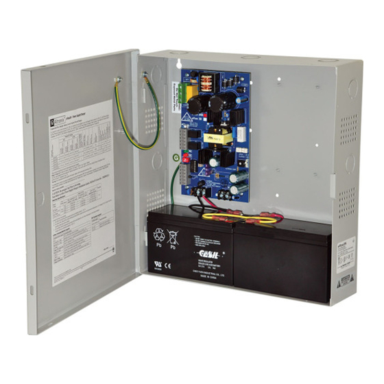
eFlow3N Series
Power Supply/Chargers
Models Include:
eFlow3N/eFlow3NX
- 2A @ 12VDC or 24VDC Class 2 Power-Limited Output
eFlow3N4/eFlow3NX4
- 2A @ 12VDC or 24VDC
- Four (4) Class 2 Power-Limited Fused Outputs
eFlow3N4D/eFlow3NX4D
- 2A @ 12VDC or 24VDC
- Four (4) Class 2 Power-Limited PTC Outputs
Installation Guide
Rev. 3NRP013019
Installing Company: _______________ Service Rep. Name: __________________________________
Address: _____________________________________________ Phone #: __________________
Altronix Corp.
140 58th St. Brooklyn, NY
More than just power.
TM
Advertisement
Table of Contents

Related Manuals for Altronix eFlow3N


Summary of Contents for Altronix eFlow3N
- Page 1 Series Power Supply/Chargers Models Include: eFlow3N/eFlow3NX - 2A @ 12VDC or 24VDC Class 2 Power-Limited Output eFlow3N4/eFlow3NX4 - 2A @ 12VDC or 24VDC - Four (4) Class 2 Power-Limited Fused Outputs eFlow3N4D/eFlow3NX4D - 2A @ 12VDC or 24VDC - Four (4) Class 2 Power-Limited PTC Outputs Installation Guide Altronix Corp.
- Page 2 Overview: Altronix eFlow3N power supply/chargers convert a 120VAC / 60Hz input to a 12VDC or 24VDC nominal output (see Power Supply Configuration Reference Chart and Specifications). eFlow3N Series Power Supply Configuration Reference Chart: Nominal DC Outputs [DC] [AUX] eFlow3N –...
-
Page 3: Specifications
4. Measure output voltage before connecting devices. This helps avoiding potential damage. 5. Connect devices to be powered: a. For eFlow3N/eFlow3NX connect devices to terminals marked [– DC +] (Fig. 1h, pg. 5). b. For other Power Distribution Models connect devices to be powered to terminal pairs 1 to 4 marked [1P &... -
Page 4: Maintenance
[Trigger EOL Shutdown] (Fig. 1e, pg. 5). 12. For Access Control Applications: mount UL Listed tamper switch (Altronix Model TS112 or equivalent) at the top of the enclosure. Slide tamper switch bracket onto the edge or the enclosure approx. 2” from the right side (Fig. -
Page 5: Terminal Identification
Power Distribution Module Terminal Legend PD4UL/PD4ULCB Function/Description 1P to 4P Positive DC power outputs. 1N to 4N Negative DC power outputs. Fig. 1 - eFlow3N Board Configuration 3A 32V 5A 250V 5A 250V BAT FAIL AC FAIL AC DELAY SHUTDOWN 1 min. - Page 6 1P-4P Power Outputs, Board 1N-4N Common Outputs (Factory Installed) Fig. 3b - PD4ULCB - Power Distribution Board DC Output to devices From Power Supply 1P-4P Power Outputs, Board 1N-4N Common Outputs (Factory Installed) - 6 - eFlow3N Series Installation Guide...
- Page 7 Fig. 4 - eFlow3N Configuration Enclosure Edge of Enclosure Tamper Switch (included) To Access Control Panel or UL Listed Reporting Device Green Lead 120VAC power mains PD4UL/ non power-limited PD4ULCB Switch Detail DC Output Switch On - 12V Devices Switch Off - 24V (power-limited) Battery &...
- Page 8 NEC Power-Limited Wiring Requirements for eFlow3N Models: Power-limited and non power-limited circuit wiring must remain separated in the cabinet. All power-limited circuit wiring must remain at least 0.25” away from any non power-limited circuit wiring. Furthermore, all power-limited circuit wiring and non power-limited circuit wiring must enter and exit the cabinet through different conduits.
- Page 9 Keep power-limited wiring separate from non power-limited. Use minimum 0.25" spacing. 12AH Rechargeable batteries are the largest batteries that can fit in this enclosure. A UL listed external battery enclosure must be used if using 40AH or 65AH batteries. eFlow3N Series Installation Guide - 9 -...
- Page 10 Distribution (power-limited) DC Output (power- limited) Battery Connections (non power-limited) Fig. 7a Incorrect Wire Correct Wire Handling Handling External Jacketed Shield Wire Insulation Pull back Solid Copper external jacketed Conductors shield approx. 1/2”. - 10 - eFlow3N Series Installation Guide...
- Page 11 (30.5mm) 0.75” 0.75” 12.5” (317.5mm) 1.20” 1.20” (19.1mm) (19.1mm) (30.5mm) (30.5mm) 11.0” (279.4mm) 0.9375” (23.8mm) 1.40” 1.40” (35.6mm) (35.6mm) 0.9375” (23.8mm) 3.25” (82.6mm) 3.25” (82.6mm) 1.0” (25.4mm) 1.0” 1.0” 10.5” (266.7mm) (25.4mm) (25.4mm) eFlow3N Series Installation Guide - 11 -...
- Page 12 (31.8mm) 1.1” (27.9mm) 1.1” (27.9mm) 1.375” 1.5” 1.5” (34.9mm) (38.1mm) (38.1mm) 1.125” (28.6mm) 2.0” (50.8mm) 2.0” (50.8mm) 1.25” (31.8mm) 1.25” (31.8mm) 1.1” (27.9mm) 1.75” (44.5mm) 1.5” 1.5” 4.615” (117.2mm) 4.615” (117.2mm) (38.1mm) (38.1mm) - 12 - eFlow3N Series Installation Guide...
-
Page 13: Appendix A - Ul Listed Compatible Devices
Appendix A - UL Listed Compatible Devices –––––––––––––––––––––––––––––––––––––––––––––––––––––––––––––––––––––––––––––––––––––––––– A.1 Four (4) Wire Smoke Detectors Table A-1 below lists four (4) wire smoke detectors compatible with eFlow3N output. System Sensor Smoke Max Stand-by Alarm Current Detector Type Detector/Base Current (mA) (mA) - Page 14 - UL Listed in the U.S. and Canada. - Local or remote control of up to (2) two Altronix eFlow power output(s) via LAN and/or WAN. - Monitor real time diagnostics: DC output voltage, output current, AC & battery status/service, input trigger state change, output state change and unit temperature.
- Page 15 Notes: Altronix is not responsible for any typographical errors. –––––––––––––––––––––––––––––––––––––––––––––––––––––––––––––––––––––––––––––––––––––––––––––––––––––––––––––––– 140 58th Street, Brooklyn, New York 11220 USA | phone: 718-567-8181 | fax: 718-567-9056 website: www.altronix.com | e-mail: info@altronix.com | Lifetime Warranty IIeFlow3N Series G21U MEMBER eFlow3N Series Installation Guide...
- Page 16 3.5A 960mV eFlow3NX, eFlow3NX4, eFlow3NX4D Overview: The eFlow3N series power supply/chargers convert a 120VAC, 60Hz input to a 12VDC or 24VDC output. Stand-by Specifications: Burg. Applications Fire Applications 4 hr. Stand-by/ 24 hr. Stand-by/ Access Control Battery 15 min. Alarm 5 min.
Need help?
Do you have a question about the eFlow3N and is the answer not in the manual?
Questions and answers