Table of Contents
Advertisement
Quick Links
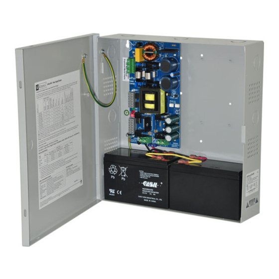
eFlow104N Series
Power Supply/Chargers
Models Include:
eFlow104N/
eFlow104NX
- 10A @ 24VDC
eFlow104N8/
eFlow104NX8
- 10A @ 24VDC
- Eight (8) Fused Outputs
eFlow104N16/
eFlow104NX16
- 10A @ 24VDC
- Sixteen (16) Fused Outputs
Installation Guide
Rev. 104NRP021119
Installing Company: _______________ Service Rep. Name: __________________________________
Address: _____________________________________________ Phone #: __________________
eFlow104N8D/
eFlow104NX8D
- 10A @ 24VDC
- Eight (8) PTC Protected
Class 2 Power-Limited Outputs
eFlow104N16D/
eFlow104NX16D
- 10A @ 24VDC
- Sixteen (16) PTC Protected
Class 2 Power-Limited Outputs
Altronix Corp.
140 58th St. Brooklyn, NY
More than just power.
TM
Advertisement
Table of Contents

Related Manuals for Altronix eFlow104N Series


Summary of Contents for Altronix eFlow104N Series
- Page 1 Series Power Supply/Chargers Models Include: eFlow104N/ eFlow104NX - 10A @ 24VDC eFlow104N8/ eFlow104N8D/ eFlow104NX8 eFlow104NX8D - 10A @ 24VDC - 10A @ 24VDC - Eight (8) Fused Outputs - Eight (8) PTC Protected Class 2 Power-Limited Outputs eFlow104N16/ eFlow104N16D/...
- Page 2 Overview: Altronix eFlow104N power supply/chargers convert a 120VAC / 60Hz input to a 24VDC nominal output (see Power Supply Configuration Reference Chart and Specifications). eFlow104N Series Power Supply Configuration Reference Chart: Nominal DC Outputs [DC] [AUX] eFlow104N – – –...
-
Page 3: Specifications
Prevents deep battery discharge. eFlow104N series Power Supply Configuration Fuse/PTC Ratings: Reference Chart, pg. 2. • Auxiliary Class 2 power-limited output • Refer to eFlow104N Series Power Supply rated @ 1A (unswitched). Configuration Reference Chart, pg. 2. • Overvoltage protection. Visual Indicators: Battery Backup: •... -
Page 4: Maintenance
[Trigger EOL Shutdown] (Fig. 1e, pg. 5). 11. For Access Control Applications: mount UL Listed tamper switch (Altronix model TS112 or equivalent) at the top of the enclosure. Slide tamper switch bracket onto the edge or the enclosure approx. 2” from the right side (Fig. -
Page 5: Terminal Identification
Connect the circuit to the Batt Fail relay contacts to an appropriate input of a UL Listed Burglar Alarm or Access Control Panel. The following figure shows the circuitry needed for local annunciation. eFlow104N Series Installation Guide - 5 -... - Page 6 From From Power Power Supply Supply Board Board (Factory (Factory Installed) Installed) For continuous protection against risk of fire replace fuses with same type and rating 3.5A 250V - 6 - eFlow104N Series Installation Guide...
- Page 7 Keep power-limited wiring separate from non power-limited. Use minimum 0.25" spacing. 7AH Rechargeable batteries are the largest batteries that can fit in this enclosure. A UL Listed external battery enclosure must be used if using 12AH, 40AH or 65AH batteries. eFlow104N Series Installation Guide - 7 -...
- Page 8 Fig. 6a Handling Handling External Jacketed Shield Wire Insulation * Outputs are non power-limited: eFlow104N, eFlow104N8, eFlow104N16. Outputs are Class 2 power-limited: Pull back Solid Copper eFlow104N8D, eFlow104N16D. external jacketed Conductors shield approx. 1/2”. - 8 - eFlow104N Series Installation Guide...
- Page 9 Keep power-limited wiring separate from non power-limited. Use minimum 0.25" spacing. 12AH Rechargeable batteries are the largest batteries that can fit in this enclosure. A UL listed external battery enclosure must be used if using 40AH or 65AH batteries. eFlow104N Series Installation Guide - 9 -...
- Page 10 Correct Wire Handling Handling External Jacketed Shield Wire Insulation * Outputs are non power-limited: eFlow104NX, eFlow104NX8, eFlow104NX16. Outputs are Class 2 power-limited: Pull back Solid Copper external jacketed Conductors eFlow104NX8D, eFlow104NX16D. shield approx. 1/2”. - 10 - eFlow104N Series Installation Guide...
- Page 11 (30.5mm) 0.75” 0.75” 12.5” (317.5mm) 1.20” 1.20” (19.1mm) (19.1mm) (30.5mm) (30.5mm) 11.0” (279.4mm) 0.9375” (23.8mm) 1.40” 1.40” (35.6mm) (35.6mm) 0.9375” (23.8mm) 3.25” (82.6mm) 3.25” (82.6mm) 1.0” (25.4mm) 1.0” 1.0” 10.5” (266.7mm) (25.4mm) (25.4mm) eFlow104N Series Installation Guide - 11 -...
- Page 12 (31.8mm) 1.1” (27.9mm) 1.1” (27.9mm) 1.375” 1.5” 1.5” (34.9mm) (38.1mm) (38.1mm) 1.125” (28.6mm) 2.0” (50.8mm) 2.0” (50.8mm) 1.25” (31.8mm) 1.25” (31.8mm) 1.1” (27.9mm) 1.75” (44.5mm) 1.5” 1.5” 4.615” (117.2mm) 4.615” (117.2mm) (38.1mm) (38.1mm) - 12 - eFlow104N Series Installation Guide...
-
Page 13: Appendix A - Ul Listed Compatible Devices
Table A-2 below lists relays compatible with eFlow104N output. Manufacturer Model Current (mA) Manufacturer Model Current (mA) PR-1 R-20T PR-2 R-24T PR-3 R-10E System Sensor System Sensor EOLR-1 R-14E R-10T R-20E R-14T R-24E eFlow104N Series Installation Guide - 13 -... - Page 14 - UL Listed in the U.S. and Canada. - Local or remote control of up to (2) two Altronix eFlow power output(s) via LAN and/or WAN. - Monitor real time diagnostics: DC output voltage, output current, AC & battery status/service, input trigger state change, output state change and unit temperature.
- Page 15 Notes: Altronix is not responsible for any typographical errors. –––––––––––––––––––––––––––––––––––––––––––––––––––––––––––––––––––––––––––––––––––––––––––––––––––––––––––––––– 140 58th Street, Brooklyn, New York 11220 USA | phone: 718-567-8181 | fax: 718-567-9056 website: www.altronix.com | e-mail: info@altronix.com | Lifetime Warranty IIeFlow104N Series G26U MEMBER eFlow104N Series Installation Guide...
- Page 16 4.5A – 700mV eFlow104NX, eFlow104NX8, Flow104NX8D, eFlow104NX16, eFlow104NX16D Overview: The eFlow104N series power supply/chargers convert a 120VAC, 60Hz input to a 24VDC output. Stand-by Specifications: Burg. Applications Fire Applications 4 hr. Stand-by/ 24 hr. Stand-by/ Access Control Battery 15 min.
Need help?
Do you have a question about the eFlow104N Series and is the answer not in the manual?
Questions and answers