Table of Contents
Advertisement
Quick Links
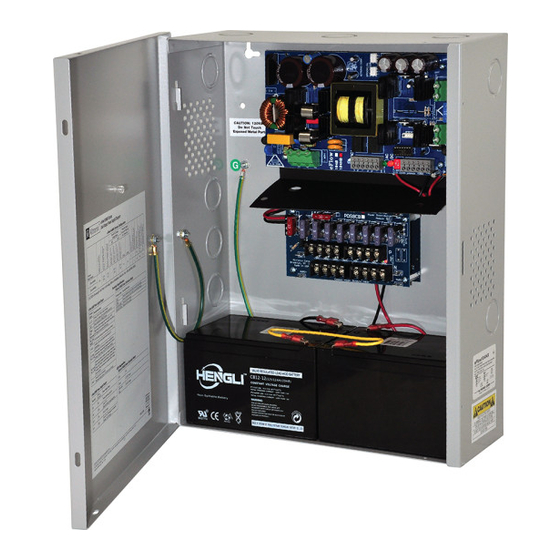
Dual Output Power Supply/Charger
Models Include:
eFlow104NK8
- 12VDC up to 6A and/or 24VDC up to 10A (240W total power)
selectable by output.
- Eight (8) fuse protected outputs.
- Built-in Charger for sealed lead acid or gel type batteries.
eFlow104NK8D
- 12VDC up to 6A and/or 24VDC up to 10A (240W total power)
selectable by output.
- Eight (8) Class 2 power-limited PTC protected outputs.
- Built-in Charger for sealed lead acid or gel type batteries.
Installation Guide
Rev. eFlow104NK8-110620
More than just power.
TM
Advertisement
Table of Contents

Related Manuals for Altronix EFLOW eFlow104NK8


Summary of Contents for Altronix EFLOW eFlow104NK8
- Page 1 Dual Output Power Supply/Charger Models Include: eFlow104NK8 - 12VDC up to 6A and/or 24VDC up to 10A (240W total power) selectable by output. - Eight (8) fuse protected outputs. - Built-in Charger for sealed lead acid or gel type batteries. eFlow104NK8D - 12VDC up to 6A and/or 24VDC up to 10A (240W total power) selectable by output.
-
Page 2: Agency Listings
Overview: Altronix eFlow104NK8 and eFlow104NK8D convert a 120VAC 60Hz input into eight (8) fuse or PTC protected 12VDC or 24VDC outputs with a total of 10A max. Units include an unswitched aux. output. They also offers a suite of features that includes fire alarm disconnect, over voltage protection, and low power disconnect which prevents deep discharge of stand-by batteries. -
Page 3: Specifications
Specifications: Inputs: Battery Backup: eFlow104NB: • Built-in charger for sealed lead acid or • 120VAC, 60Hz, 4.5A. gel type batteries. PDS8/PDS8CB: • Maximum charge current 1.54A. • 24VDC from eFlow104NB. • Automatic switch over to stand-by battery when • 12VDC from VR6 voltage regulator. AC fails. -
Page 4: Installation Instructions
12. Installation of Tamper Switch: Mount UL Listed tamper switch (Altronix model TS112 or equivalent) at the top of the enclosure. Slide the tamper switch bracket onto the edge of the enclosure approximately 2” from the right side (Fig. 3a, pg. 7). - Page 5 Fig. 2 - eFlow104N Board configuration AC FAIL BAT FAIL AC DELAY SHUTDOWN 6.3A 250V 1 min. enable TRIGGER EOL NC C NO NC C NO + AUX – 2 hr. disable RESET SUPERVISED 2e 2f eFlow104NK8(D) - 5 -...
-
Page 6: Led Diagnostics
LED Diagnostics: eFlow104NB Power Supply/Charger Red (DC) Green (AC/AC1) Power Supply Status Normal operating condition. Loss of AC. Stand-by battery is supplying power. No DC output. Loss of AC. Discharged or no stand-by battery. No DC output. PDS8(CB): Green 12VDC Output. Green and Red 24VDC Output. - Page 7 Fig. 3 - eFlow104NK8(D) Tamper Switch Power Output Factory wired to PDS8(CB) and VR6 (non power-limited) eFlow104NB Power Supply Battery Output (non power-limited) AC FAIL NC C NO NC C NO BAT FAIL Supervisory connections (power-limited) PWR1 + IN1 Fuse PDS8(CB) PWR1 + 24VDC from...
- Page 8 (38.1mm) (38.1mm) Altronix is not responsible for any typographical errors. 140 58th Street, Brooklyn, New York 11220 USA | phone: 718-567-8181 | fax: 718-567-9056 website: www.altronix.com | e-mail: info@altronix.com | Lifetime Warranty | Made in U.S.A. IIeFlow104NK8(D) K06T MEMBER - 8 -...
Need help?
Do you have a question about the EFLOW eFlow104NK8 and is the answer not in the manual?
Questions and answers