
Subscribe to Our Youtube Channel
Related Manuals for JLG 800AJ HC3


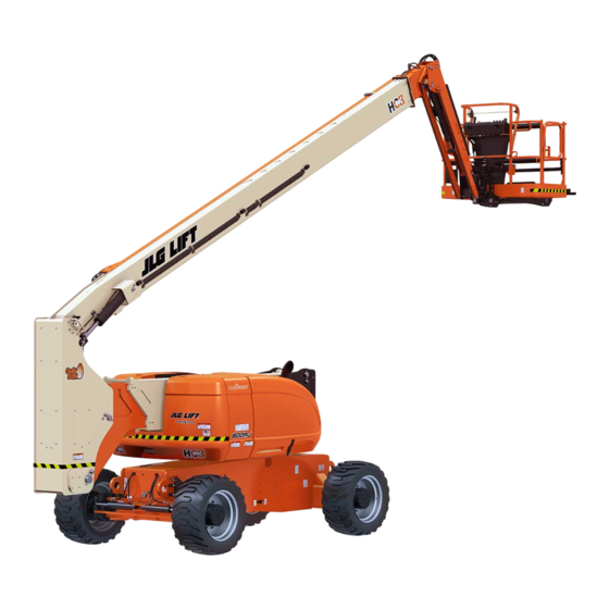
Summary of Contents for JLG 800AJ HC3
- Page 1 Operation & Safety Manual Original Instructions - Keep this manual with the machine at all times. Model 800AJ HC3 PVC 2307 31222411 July 26, 2023 - Rev B Copyright © ANSI AS/NZS MOL70 GB...
- Page 2 WARNING Operating, servicing and maintaining this vehicle or equipment can expose you to chemicals including engine exhaust, carbon monoxide, phthalates, and lead, which are known to the State of California to cause cancer and birth defects or other re- productive harm. To minimize exposure, avoid breathing exhaust, do not idle the engine except as necessary, service your vehicle or equipment in a well-ventilated area and wear gloves or wash your hands frequently when servicing.
-
Page 3: Foreword
Due to continuous product improvements, JLG Industries, Inc. reserves the right to make specification changes without prior notification. Contact JLG Industries, Inc. for updated information. - Page 4 It may also alert against unsafe practices. This decal will have a yellow background. NOTICE Indicates information or a company policy that relates directly or indirectly to the safety of personnel or protection of property. 31222411 800AJ HC3...
- Page 5 NOTICE JLG Industries, Inc. sends safety related bulletins to the owner of record of this machine. Contact JLG Industries, Inc. to ensure that the current owner records are updated and accurate.
- Page 6 Questions Regarding Product Modifications Contact: Product Safety and Reliability Department JLG Industries, Inc. 13224 Fountainhead Plaza Hagerstown, MD 21742 or Visit www.jlg.com to find your local JLG office. In USA: Toll Free: 877-JLG-SAFE (877-554-7233) Outside USA: Phone: 240-420-2661 Fax: 301-745-3713 E-mail: ProductSafety@JLG.com...
-
Page 7: Revision Log
REVISION LOG Description Date Revision July 10, 2023 Original Issue July 26, 2023 Revision Other Publications Available Publication Publication Number 31222412 Service & Maintenance Manual 31222413 Illustrated Parts Manual 800AJ HC3 31222411... - Page 8 This Page is intentionally left blank...
-
Page 9: Table Of Contents
SECTION 3 MACHINE CONTROLS AND INDICATORS........41 General................41 Controls and Indicators ............42 Ground Control Station............43 Ground Control Indicator Panel..........47 Platform Control Station ............. 50 Platform Control Indicator Panel .......... 55 Beacons ................58 800AJ HC3 31222411... - Page 10 SECTION 4 MACHINE OPERATION..............61 General................61 Operating Characteristics and Limitations......61 800AJ HC3 Reach Chart............64 Engine Operation............... 65 Air Shutoff Valve (ASOV) (If Equipped)........68 Fuel Reserve / Shut-Off System ..........69 Diesel Particulate Filter (If Equipped)........69 Traveling (Grade and Side Slope)..........
- Page 11 Propane Fuel Filter Replacement ........151 Propane Fuel System Pressure Relief ........152 7.10 Radio Frequency (RF) Information........153 7.11 Supplemental Information Only Applicable to CE/UKCA Machines ................ 154 7.12 EC Declaration of Conformity..........155 7.13 UKCA Declaration of Conformity ........156 800AJ HC3 31222411...
- Page 12 This Page is intentionally left blank...
-
Page 13: Safety Precautions
Read, understand, and study the Operation and Safety Manual in its entirety before operating the machine. For clarification, questions, or additional information regarding any portions of this manual, contact JLG Industries, Inc. • Only personnel who have received proper training regarding the inspection, application and operation of MEWPs (including recognizing and avoiding hazards associated with their operation) shall be authorized to operate a MEWP. - Page 14 • Check the work area for hazardous locations. Do not operate the machine in hazardous environments unless approved for that purpose by JLG. • Ensure that the ground conditions are adequate to support the maximum tire load indicated on the tire load decals located on the chassis adjacent to each wheel.
-
Page 15: Operation
Do not allow personnel to tamper with or operate the machine from the ground with personnel in the platform, except in an emergency. • Do not carry materials directly on platform railing unless approved by JLG. • When two or more persons are in the platform, the operator shall be responsible for all machine operations. - Page 16 Ensure that the platform assembly is fully lowered. Face the platform when entering or leaving the platform. Always maintain “three point contact” with the machine, using two hands and one foot or two feet and one hand at all times during entry and exit. 31222411 800AJ HC3...
- Page 17 10 (3) 0 to 50 KV 15 (5) Over 50K V to 200 KV 20 (6) Over 200 KV to 350 KV 25 (8) Over 350 KV to 500 KV 35 (11) Over 500 KV to 750 KV 800AJ HC3 31222411...
- Page 18 The user must be familiar with the operating surface before driving. Do not exceed the allowable side slope and grade while driving. • Do not elevate platform or drive with platform elevated while on or near a sloping, uneven, or soft surface. 31222411 800AJ HC3...
- Page 19 • Never exceed the maximum platform capacity as specified on the platform. Keep all loads within the confines of the platform, unless authorized by JLG. • Keep the chassis of the machine a minimum of 2 ft (0.6m) from holes, bumps, drop- offs, obstructions, debris, concealed holes, and other potential hazards at the ground level.
- Page 20 Use the boom functions, not the drive function, to position the platform close to obstacles. • Always post a lookout when driving in areas where vision is obstructed. • Keep non-operating personnel at least 6 ft (1.8 m) away from machine during all operations. 31222411 800AJ HC3...
-
Page 21: Towing, Lifting, And Hauling
1.5.1 Maintenance Hazards • Shut off power to all controls and ensure that all moving parts are secured from inadvertent motion prior to performing any adjustments or repairs. 800AJ HC3 31222411... - Page 22 Wear gloves to help protect hands from spraying fluid. • Use only replacement parts or components that are approved by JLG. To be considered approved, replacement parts or components must be identical or equivalent to original parts or components.
- Page 23 Immediately rinse any contacted area with clean water and seek medical attention. • Charge batteries only in a well ventilated area. • Avoid overfilling the battery fluid level. Add distilled water to batteries only after the batteries are fully charged. 800AJ HC3 31222411...
- Page 24 This Page is intentionally left blank...
-
Page 25: User Responsibilities, Machine Preparation, And Inspection
2.1.3 Operator Responsibility The operator must be instructed that they have the responsibility and authority to shut down the machine in case of a malfunction or other unsafe condition of either the machine or the job site. 800AJ HC3 31222411... -
Page 26: Preparation, Inspection, And Maintenance
6. Accessories and optional equipment. PREPARATION, INSPECTION, AND MAINTENANCE The following table covers machine inspections and maintenance required by JLG Industries, Inc. Consult local regulations for further requirements for MEWPs. The frequency of inspections and maintenance must be increased as necessary when the machine is used in a harsh or hostile environment, if the machine is used with increased frequency, or if the machine is used in a severe manner. - Page 27 Owner, Dealer, or Qualified JLG Service & Mainte- nance Manual and tion (See Note) lease, or rental User Mechanic delivery applicable JLG in- spection form Frequent Inspection In service for 3 Owner, Dealer, or Qualified JLG Service & Mainte- (See Note) User...
-
Page 28: Machine Components
Manual Service & Mainte- nance Manual Note: Inspection forms are available from JLG. Use the Service & Maintenance Manual to perform inspections. NOTICE JLG Industries, Inc. recognizes a factory trained service technician as a person who has successfully completed the JLG Service Training School for the specified JLG product model. -
Page 29: Pre-Start Inspection
8. Engine Oil Supply — Ensure the engine oil level is at the Full mark on the dipstick and the filler cap is secure. 9. Hydraulic Oil — Check the hydraulic oil level. Ensure hydraulic oil is added as required. 800AJ HC3 31222411... -
Page 30: Walk-Around Inspection
Attach only one (1) lanyard per lanyard anchorage point. WARNING If the machine does not operate properly, turn off the machine immediately! Report the problem to the proper maintenance personnel. Do not operate the machine until it is declared safe for operation. WALK-AROUND INSPECTION OAC014170 31222411 800AJ HC3... - Page 31 13. Ground Control Console - Switches and levers return to neutral when activated and released, decals/placards secure and legible, control markings legible. 14. Hood Assemblies - See Inspection Note. 15. Auxiliary Hydraulic Pump - See Inspection Note. 800AJ HC3 31222411...
-
Page 32: Function Check
Ensure all functions stop when the function switch is released. c. Operate all functions and ensure proper operation. d. Ensure proper operation of the manual descent controls, as described in Section — Machine Safety System Override (MSSO) (CE Only) of this manual. 31222411 800AJ HC3... - Page 33 (rear) of the tower base boom. Open the left side hood and perform a visual check that the plunger on the tower boom vertical limit switch is fully extended. The plunger is shown fully extended in Figure — Tower Boom Vertical Limit Switch, page 800AJ HC3 31222411...
- Page 34 Check that the plunger on the tower boom horizontal limit switch at the end of the tower base boom section is fully extended. The plunger is shown fully extended in Figure — Tower Boom Horizontal Limit Switch, page 31222411 800AJ HC3...
- Page 35 User Responsibilities, Machine Preparation, and Inspection BM000502A Figure 4. Tower Boom Horizontal Limit Switch WARNING Discontinue operation if plunger is not fully extended. 800AJ HC3 31222411...
- Page 36 User Responsibilities, Machine Preparation, and Inspection 90° 90° BM000503A WARNING Upright must be 90° (vertical) relative to the chassis. Figure 5. Boom Upright Positioning - Correct 31222411 800AJ HC3...
- Page 37 BM000504A WARNING To avoid tipping if this occurs: lower platform to ground using main boom lift and telescope functions. Have condition corrected by a trained JLG service technician before continuing use of machine. Figure 6. Boom Upright Positioning - Incorrect e.
- Page 38 6. With the machine positioned on a smooth, firm surface within the limits of the maximum operating slope, elevate the boom above 4 degrees of horizontal. Select high speed drive mode. Carefully attempt to drive and ensure the drive speed is reduced. 31222411 800AJ HC3...
-
Page 39: Skyguard® Function Test
Note: Ensure boom is fully retracted, lowered, and centered between drive wheels pri- or to beginning lockout cylinder test. 1. Place a 6 in (15.2 cm) high block with ascension ramp in front of left front wheel. 2. From platform control station, start engine. 800AJ HC3 31222411... - Page 40 Drive to release cylinders. 15. If lockout cylinders do not function properly, have qualified personnel correct the malfunction prior to any further operation. 31222411 800AJ HC3...
-
Page 41: Machine Controls And Indicators
Machine Controls and Indicators GENERAL NOTICE The manufacturer has no direct control over machine application and operation. The user and operator are responsible for conforming with good safety practices. This section provides the necessary information needed to understand control functions. 800AJ HC3 31222411... -
Page 42: Controls And Indicators
This indicator will be yellow. Indicates important information regarding the oper- ating condition, i.e. procedures essential for safe op- eration. This indicator will be green with the exception of the capacity indicator which will be yellow. 31222411 800AJ HC3... -
Page 43: Ground Control Station
12. Main Boom Lift 13. Main Boom Telescope 14. Indicator Panel 15. Air Shutoff Valve (ASOV) (If Equipped) 800AJ HC3 Ground Control Station without MSSO 1. Platform Rotate 2. Platform Leveling Override Switch 3. Jib 4. Power / Emergency Stop Switch 5. - Page 44 12. Tower Lift 13. Tower Telescope 14. Main Boom Lift 15. Main Boom Telescope 16. Indicator Panel 800AJ HC3 Ground Control Station with MSSO and DPF 3.3.1 Ground Control Station Functions WARNING To avoid serious injury, do not operate machine if any control levers or toggle switches controlling platform movement do not return to the off or neutral position when released.
- Page 45 Provides raising and lowering of the jib. Machine Safety System Override (MSSO) (If Equipped) Provides emergency override of function controls that are locked out in the event of Load Sense System activation. Main Boom Lift Provides raising and lowering of the main boom. 800AJ HC3 31222411...
- Page 46 Always position emergency stop switch to the Off position (pushed in) when machine is not in use. Swing Provides 360 degrees continuous turntable rotation. Tower Boom Lift This switch provides raising and lowering of the tower boom. This function works only when the tower boom is fully retracted. 31222411 800AJ HC3...
-
Page 47: Ground Control Indicator Panel
GROUND CONTROL INDICATOR PANEL 1. Battery Charge 7. Fuel Gauge 8. Boom Malfunction 2. System Distress 3. Drive and Steer Disable 9. Platform Overload 4. Capacity Zone Indicator 10. Engine Error 5. AC Generator 11. Emissions Temperature 6. Glow Plug 800AJ HC3 31222411... - Page 48 Note: Refer to the capacity decals on the machine for restricted and unrestricted platform capacities. Drive and Steer Disable Indicates the Drive and Steer Disable function has been activated. Emissions Temperature Indicator illuminates when exhaust temperature reaches 1022° F (550° C). 31222411 800AJ HC3...
- Page 49 Indicates the level of the fuel in the fuel tank. ½ Glow Plug Indicates the glow plugs are on. The glow plugs are automatically turned on with the ignition circuit and remain on for approximately seven seconds. Start the engine only after the light goes out. 800AJ HC3 31222411...
-
Page 50: Platform Control Station
Indicates the platform has been overloaded. System Distress The light indicates that the JLG Control System has detected an abnormal condition and a Diagnostic Trouble Code has been set in the system memory. Refer to the Service Manual for instructions concerning the trouble codes and trouble code retrieval. - Page 51 The auxiliary pump functions to provide sufficient oil flow to operate the basic machine functions should the main pump or engine fail. The auxiliary pump will operate tower boom lift, tower telescope, main boom lift, main telescope and swing. 800AJ HC3 31222411...
- Page 52 Note: The ignition switch does not have to be on to operate the lights, so care must be taken to avoid draining the battery if left unattended. The master switch and/or the ignition switch at the ground control will turn off power to all lights. Main Boom Telescope Provides extension and retraction of the main boom. 31222411 800AJ HC3...
- Page 53 The switch operates like the SkyGuard override switch as described above. The switch also enables the functions cut out by the SkySense system to operate again at creep speed, allowing the operator to move the platform closer to the obstacle that caused the shutdown situation if desired. 800AJ HC3 31222411...
- Page 54 Note: Tower Telescope should not function when Tower Lift is not fully elevated (in the up position). WARNING To avoid serious injury, do not operate machine if tower lift and telescope do not operate in the order described above. 31222411 800AJ HC3...
-
Page 55: Platform Control Indicator Panel
When an audible alarm sounds and the Boom Malfunction Indicator illuminates steady without a boom function attempt, the upright is out of alignment. WARNING Discontinue operation if the upright is out of alignment or the boom malfunction light remains illuminated. 800AJ HC3 31222411... - Page 56 (i.e. controls reversed situations). Emissions Temperature Icon illuminates when the engine emissions control sensor reaches a high temperature. Engine Emissions System Failure Icon illuminates when there is a fault with the Emissions After Treatment system. 31222411 800AJ HC3...
- Page 57 Indicates the level of the fuel in the fuel tank. ½ Glow Plug Indicates the glow plugs are operating. After turning on ignition, wait until light goes out before cranking engine. Platform Overload Indicates the platform has been overloaded. 800AJ HC3 31222411...
-
Page 58: Beacons
Machine Controls and Indicators System Distress The light indicates that the JLG Control System has detected an abnormal condition and a Diagnostic Trouble Code has been set in the system memory. Refer to the Service Manual for instructions concerning the trouble codes and trouble code retrieval. - Page 59 Blue or Red SkyGuard® Beacon The SkyGuard beacon is available in blue or red lamp options. The beacon will flash in conjunction with an audible alarm when the SkyGuard sensor is activated. Refer to the SkyGuard Operation section for more information. 800AJ HC3 31222411...
- Page 60 This Page is intentionally left blank...
-
Page 61: Machine Operation
2. Load is within manufacturer’s rated capacity. 3. All machine systems are functioning properly. 4. Machine is as originally equipped from JLG. 4.2.2 Platform Load Sensing System (LSS) The Platform Load Sensing System provides the platform load to the control system. - Page 62 2. Main boom fully retracted. Machine will tip over in this direction if tower boom upright is placed beyond this position or operated beyond the limits of the maximum op- erating slope. OAC014210 Figure 7. Positions of Least Backward Stability 31222411 800AJ HC3...
- Page 63 1. Level surface. 2. Tower boom full elevated and fully retracted. 3. Main boom level and fully extended. Machine will tip over in this direction if over- loaded or operated beyond the limits of the maximum operating slope. 800AJ HC3 31222411...
-
Page 64: 800Aj Hc3 Reach Chart
Machine Operation 800AJ HC3 REACH CHART 31222411 800AJ HC3... -
Page 65: Engine Operation
Note: When operating a machine at high ambient temperatures, a decrease in ma- chine performance and an increase in engine coolant temperature may occur. Note: Contact JLG Customer Service for operation under abnormal conditions. Note: Initial starting should always be performed from the Ground Control station. - Page 66 Allow engine to warm-up for a few minutes at low speed before applying any load. After engine has had sufficient time to warm up, push in the Power/ Emergency Stop switch and shut engine off. Turn Platform/Ground Select switch to Platform. From Ground Control Console, pull Power/ Emergency Stop switch out. 31222411 800AJ HC3...
- Page 67 Remove all load and allow engine to operate at low speed for 3-5 minutes; this allows further reduction of internal engine temperature. Push Power/Emergency Stop switch in. Turn Platform/Ground Select switch to Off. Note: Refer to Engine Manufacturer’s manual for detailed information. 800AJ HC3 31222411...
-
Page 68: Air Shutoff Valve (Asov) (If Equipped)
Note: The handle cannot be turned unless the machine is off. Ensure the ignition power is OFF. WARNING Do not use ASOV as an alternative to shutting down machine properly. Figure 9. ASOV Reset (Closed to Open Position) 31222411 800AJ HC3... -
Page 69: Fuel Reserve / Shut-Off System
2 minutes of run time. The operator can repeat this process until there is no more fuel available. NOTICE Contact a qualified JLG mechanic if the machine needs restarted after no more fuel is available. •... -
Page 70: Traveling (Grade And Side Slope)
(drive) axle, and in line with the direction of travel. Drive the machine forward when climbing a grade, and in reverse when descending a grade. Do not exceed the machine's maximum rated gradeability. Figure 10. Traveling on a Grade 31222411 800AJ HC3... - Page 71 Machine Operation NOTICE If the boom is over the front (steer) axle, direction of steer and drive movement will be opposite from the movement of the controls. Figure 11. Grade and Sideslope 800AJ HC3 31222411...
-
Page 72: Traveling (Driving)
Use extreme caution when driving in reverse and at all times when the platform is elevated. Before driving, locate the black/white orientation arrows on both the chassis and the platform controls. Move the drive controls in a direction matching the directional arrows for the intended direction of travel. 31222411 800AJ HC3... - Page 73 Position Drive controller to Forward or Reverse as desired. This machine is equipped with a Drive Orientation Indicator. The yellow light on the platform control console indicates that the boom is swung beyond the rear drive tires 800AJ HC3 31222411...
-
Page 74: Steering
WARNING To avoid serious injury, do not operate machine if any control lever or toggle switch controlling platform movement does not return to the ‘off’ or neutral position when released. 31222411 800AJ HC3... - Page 75 Raising and Lowering the Tower Boom This machine has two controls for the tower boom (two toggle switches), one controls tower lift, the other tower telescope. The switching system will sequence its Lift and Telescope functions as follows: 800AJ HC3 31222411...
- Page 76 To avoid tipping machine if tower boom switching malfunction: • Lower platform to ground using main boom lift and telescope functions. • Have condition corrected by a qualified JLG service technician before continuing use of machine. 4.11.3 Raising and Lowering the Main Boom To raise or lower the Main Boom, position the Main Boom Lift switch to Up or Down until the desired height is reached.
-
Page 77: Function Speed Control
(if available) restrictions. Refer to the Access Control and Beacons sections of this manual for more information. Visit the ClearSky section of the JLG website for more resources and information about accessing web portal or mobile app data. 800AJ HC3... -
Page 78: Access Control - Clearsky Smart Fleet™ (If Equipped)
The Locked Out state will override the machine capability to use auxiliary power. Note: Restricted functionality may occur if the CS550 (ClearSky® LED Motion / Amber Beacon) is damaged or removed. A protective cage is available through JLG. Machines equipped with ClearSky Smart Fleet Access Control are also equipped with the CS550. -
Page 79: Machine Safety System Override (Msso) (If Equipped)
Consult the following illustrations to determine which type of SkyGuard the machine has and how it is activated. Regardless of type, SkyGuard function according to the SkyGuard Function Table does not change. 4.17.1 SkyGuard OAC00110 Approximately 50 lb (222 Nm) of force is applied to yellow bar. 800AJ HC3 31222411... - Page 80 Machine Operation 4.17.2 SkyGuard - SkyLine OAC03970 Rod is pressed, breaking the connection between the rod and right bracket. 4.17.3 SkyGuard - SkyEye OAC00140 Operator passes through path of sensor beam. 31222411 800AJ HC3...
- Page 81 Machine Operation 800AJ HC3 31222411...
-
Page 82: Shut Down And Park
4.19 LIFTING AND TIE DOWN 4.19.1 Lifting 1. Refer to the Machine Serial Number Plate, call JLG Industries, or weigh the individual unit to find out the Gross Vehicle Weight. 2. Place the boom in the stowed position. 3. Remove all loose items from the machine. -
Page 83: Lifting Chart
Note: Secure through the tie downs on the boom using straps or chains of adequate strength. OAC014470 NOTICE Secure turntable with turntable lock (if equipped) before traveling long distances or hauling machine on truck/trailer. 4.20 LIFTING CHART 800AJ HC3 31222411... -
Page 84: Re-Synchronize Upright
6. Lower the tower boom fully and continue to hold down the switch to Tower Down for an additional 20 seconds. 7. Repeat steps 3 through 6 as necessary until the upright is 90° (vertical) relative to the chassis. 31222411 800AJ HC3... -
Page 85: Safety Decals
Machine Operation Figure 12. Re-leveling Valve 4.22 SAFETY DECALS 4.22.1 Safety Decal Location BM001209A Figure 13. Safety Decals — 1 of 5 800AJ HC3 31222411... - Page 86 Machine Operation 33, 34 BM001210A Figure 14. Safety Decals — 2 of 5 BM001211A Figure 15. Safety Decals — 3 of 5 31222411 800AJ HC3...
- Page 87 Machine Operation BM001212A Figure 16. Safety Decals — 4 of 5 BM001213A Figure 17. Safety Decals — 5 of 5 800AJ HC3 31222411...
- Page 88 Machine Operation 31222411 800AJ HC3...
- Page 89 Machine Operation 800AJ HC3 31222411...
- Page 90 Machine Operation 31222411 800AJ HC3...
- Page 91 Machine Operation 4.22.2 Safety Decal Location — CE/UKCA BM001214A Figure 18. Safety Decals CE/UKCA — 1 of 2 BM001215A Figure 19. Safety Decals CE/UKCA — 2 of 2 800AJ HC3 31222411...
- Page 92 Machine Operation Table 5. Safety Decal Legend — CE/UKCA Item # CE/UKCA 1701505 1705822 1701518 1705961 1001267312 1001234439 1001291837 1700818 1001231801 1702788 1001197408 1001180861 1001263941 1001143852 31222411 800AJ HC3...
-
Page 93: Emergency Procedures
This section explains the steps to be taken in case of an emergency situation during operation. INCIDENT NOTIFICATION JLG Industries, Inc. must be notified immediately of any incident involving a JLG product. Even if no injury or property damage is evident, the factory should be contacted by telephone and provided with all necessary details. -
Page 94: Emergency Operation
Do not operate the machine until it is declared safe for operation. EMERGENCY TOWING PROCEDURES Towing this machine is prohibited, unless properly equipped. However, provisions for moving the machine have been incorporated. For specific procedures, refer to the Machine Operation section. 31222411 800AJ HC3... -
Page 95: Clearsky Smart Fleet™ - Locked Out State
If the CS550 (ClearSky® LED Motion / Amber Beacon) is removed from a machine or disconnected from the control system through damage, the machine may also be placed into a Locked Out state. NOTICE Contact the ClearSky Smart Fleet™ account owner if the machine is in a Locked Out state. 800AJ HC3 31222411... -
Page 96: Machine Safety System Override (Msso) (If Equipped)
Note: If the MSSO functionality is used, a fault indicator is set with a fault code in the JLG Control System which must be reset by a qualified JLG Service Technician. Note: No functional checks of the MSSO system are necessary. The JLG Control System will set a Diagnostic Trouble Code if the control switch is faulty. -
Page 97: Accessories
√ √ √ √ (36” x 72”) (36” x 96”) Platform Top Rail Extension √ √ √ √ √ √ √ (36” x 72”) (36” x 96”) Platform Work √ √ √ √ √ √ √ Lights 800AJ HC3 31222411... - Page 98 4 kW SkySense® √ √ √ √ √ √ √ SkySense® Plat- form Bumper √ √ √ √ √ √ √ Padding SkyWelder® √ √ √ √ √ √ Soft Touch √ √ √ √ √ √ √ 31222411 800AJ HC3...
- Page 99 Accessories 800AJ HC3 31222411...
- Page 100 Accessories 31222411 800AJ HC3...
-
Page 101: Bolt-On External Fall Arrest
6 ft (1.8 m) in length, that limits the maximum arrest force to 900 lb (408 kg). External Fall Arrest System capacity is 310 lb (140 kg) - one (1) person maximum. Do not move platform during use of the external fall arrest system. 800AJ HC3 31222411... - Page 102 If any gap is shown between the two Belleville washers, the cable tension is incorrect. • Fittings & Brackets: Ensure all fittings are tight and there are no signs of fractures. Inspect brackets for any damage. 31222411 800AJ HC3...
-
Page 103: Fabric Mesh To Mid Or Top Rail
FALL ARREST PLATFORM Note: See the JLG External Fall Arrest System manual (PN 3128935) for more detailed information. The external fall arrest system is designed to provide a lanyard attach point while allowing the operator to access areas outside the platform. -
Page 104: Pipe Racks
This accessory consists of two racks with adjustable straps to secure the load in place. 6.5.1 Capacity Specifications (Australia Only) Max. Platform Capacity Max. Capacity in Racks (With Max. Weight in Racks) 80 kg 184 kg 31222411 800AJ HC3... - Page 105 2. Loosen and remove tie-down straps. Place material on racks with weight evenly distributed between both racks. 3. Route the tie-down straps at each end across loaded material and tighten. 800AJ HC3 31222411...
-
Page 106: Platform Mesh To Mid Or Top Rail
Figure 27. Platform Mesh to Top Rail The Platform Mesh to Mid Rail accessory consists of stainless steel mesh attached to the platform mid rail. The Platform Mesh to Top Rail accessory consists of lightweight, aluminum mesh attached to the platform top rail. 31222411 800AJ HC3... -
Page 107: Platform Work Lights
Accessories PLATFORM WORK LIGHTS OAC04000 Figure 28. Platform Work Lights The Platform Work Lights accessory consists of two 12V lights mounted to the platform railing. 800AJ HC3 31222411... -
Page 108: Platform Work Surface
Accessories PLATFORM WORK SURFACE BM000276A Figure 29. Platform Work Surface The platform work surface option consists of a corner tray bolted onto the top and mid rails of the platform. 31222411 800AJ HC3... -
Page 109: Portable Work Light
Figure 30. Portable Work Light The Portable Work Light accessory consists of a single 12V light mounted to the platform railing. The light can be moved by the operator and plugged into various 12V receptacles around the platform. 800AJ HC3 31222411... -
Page 110: Skyair
Automatic Start-Stop Control 100 - 130 psi 105 - 120 psi Constant Run Control 6.10.3 Safety Precautions WARNING Do not overload platform. • Ensure no personnel are beneath platform. • This factory-installed option is available only on specified models. 31222411 800AJ HC3... - Page 111 Ensure compressor and hoses are secure. • Check condition of belt and wiring. 6.10.5 Operation Start the engine, turn on the generator, then turn on the air compressor. See the J-Air Manual (PN 3128970) for more information. 800AJ HC3 31222411...
-
Page 112: Skycutter
Do not exit platform over rails or stand on rails. • Use this option only on approved models. • Keep lanyard attached at all times. • Use correct cutting settings. • Do not use electrical cords without ground. 31222411 800AJ HC3... - Page 113 Connect ground clamp to metal being cut. • Ensure there is a good ground connection. 6.11.4 Operation Start the engine, turn on the generator, then turn on the plasma cutter. See the Miller Plasma Cutter Owner’s Manual (PN 3128420) for more information. 800AJ HC3 31222411...
- Page 114 Accessories 31222411 800AJ HC3...
-
Page 115: Skyglazier
150 lb (68 kg) 440 lb (200 kg) 1000 lb (450 kg/454 kg) 250 lb (113 kg) 500 lb (227 kg) * Refer to the capacity decals installed on the machine for capacity zone information. Required Platform Type: Side-Entry 800AJ HC3 31222411... - Page 116 6.12.3 Preparation and Inspection • Check for cracked welds and damage to tray. • Ensure tray is properly secured to platform. • Ensure strap is not torn or frayed. 6.12.4 Operation 1. Load SkyGlazier tray with panel. 31222411 800AJ HC3...
-
Page 117: Skypower® 7.5 Kw And Generator 4 Kw
1-phase: 240 V / 120 V, 60 Hz, 6 kW (Peak: 6 kW) Generator 4 kW Specifications: • 1-phase: 240 V / 120 V, 60 Hz, 4 kW • 1-phase: 230 V / 115 V, 50 Hz, 4 kW 800AJ HC3 31222411... - Page 118 Preparation and Inspection • Ensure generator is secure. • Check condition of belt and wiring. 6.13.4 Operation Start the engine, then turn on the generator. Refer to the Miller Generator Technical Manual (PN 3121677) for more information. 31222411 800AJ HC3...
-
Page 119: Skysense
The machine should stop, and the LED corresponding to that sensor (left LED for left sensor bar; right LED for right sensor bar; both LEDs for center sensor bar or overhead sensor) should be red. 800AJ HC3 31222411... - Page 120 LED Flashing Yellow: Machine is in SkySense warning zone and will reduce function speed to creep. Flash frequency correlates to proximity of object. • LED Red: Machine is in SkySense stop zone and all machine functions will cease. 31222411 800AJ HC3...
- Page 121 When the operator overrides the SkySense via the override button to get closer to a work surface, the machine will maintain creep speed and flash the appropriate indicator color based on location in either the warning or stop zones. 800AJ HC3 31222411...
- Page 122 SkyGuard will function normally. 6.14.6 SkySense Coverage Areas BM000009A BM000010A Figure 35. SkySense Coverage Level 1 Figure 36. SkySense Coverage Level 2 Areas (2– Bar) Areas (3 — Bar) Note: Sensor Cones shown are approximations for reference only. 31222411 800AJ HC3...
-
Page 123: Skysense® Platform Bumper Padding
Accessories 6.15 SKYSENSE® PLATFORM BUMPER PADDING BM001038A Figure 37. Platform Bumper Padding This accessory outfits machines equipped with the SkySense accessory additional padding for the platform. 800AJ HC3 31222411... -
Page 124: Skywelder
See the Miller Welder Owner’s Manual (PN 31215476) for more information. 6.16.2 Generator Output Engine Speed of 1800 rpm +/- 10%. ANSI Specifications: • 3-phase: 240 V, 60 Hz, 7.5 kW • 1-phase: 240 V/120 V, 60 Hz, 6 kW 31222411 800AJ HC3... - Page 125 Accessories 800AJ HC3 31222411...
- Page 126 Do not ground through the platform. • Do not use a high frequency arc starter with TIG welder. 6.16.5 Preparation and Inspection • Connect ground clamp to metal being welded. • Ensure there is a good ground connection and observe proper polarity. 31222411 800AJ HC3...
-
Page 127: Soft Touch
A button on the platform console allows override of the system. BM000011A Figure 39. Soft Touch System 1. Override Indicator Light 2. Override Button 3. Rail Bumper 4. Limit Switch 5. Suspended Frame and Rail Bumper 6. Limit Switch 800AJ HC3 31222411... - Page 128 This Page is intentionally left blank...
-
Page 129: General Specifications And Operator Maintenance
300 kg Restricted: 340 kg Restricted: 450 kg Travel Speed 3.0 mph (4.83 kmh) Maximum Manual Side Force 90 lb (400 N) Maximum Operating Slope 5° Maximum Travel Grade, Stowed (Gradeability) Maximum Travel Grade, Stowed (Side Slope) 5° 800AJ HC3 31222411... - Page 130 Table 11. Capacities Approx. 39 gal (147.6 L) Fuel Tank Hydraulic Tank Approx. 40 gal (151.4 L) Hydraulic System (Including Tank) 77 gal (291.4 L) Drive Hub 44 oz (1.3 L) Drive Brake 2.7 oz (80 ml) Engine Crankcase 31222411 800AJ HC3...
- Page 131 Ultra Low Sulfur Diesel (15 ppm) Fuel Output 67 hp (50 kW) Torque 173 ft.lbs. (234 Nm) @ 1800rpm Oil Capacity (Crankcase) 2.4 Gallon (8.9 L) w/Filter Cooling System 3.3 Gallon (12.5 L) 1200 ±50 rpm Low RPM 2600±50 rpm High RPM 800AJ HC3 31222411...
- Page 132 Low RPM 1000±50 RPM High RPM 3200 ±5 0 RPM 150 Amp Alternator Starter 64.4 Amp@3574 RPM Fan Ratio Fuel Consumption 1 GPH (3.79 LPH) 5.34 lb/h (2.42 Kg/h) Max Output (Power) Gasoline 84HP@3200 80HP@3200 Max Output (Torque) 31222411 800AJ HC3...
- Page 133 Table 15. Critical Stability Weights COMPONENTS 15-625 Tire & Wheel Size (Foam Filled Only) 18 -625 Engine Deutz GM w/pumps 1030 4805 2180 Counterweight Turntable Wheel Hubs Rear Front 2WD Front 4WD 800AJ HC3 31222411...
- Page 134 “cold weather” hydraulic fluid (Viscosity Grade 32). Note: Aside from JLG recommendations, it is not advisable to mix oils of different brands or types, as they may not contain the same required additives or be of comparable viscosities.
- Page 135 Shell Spirax S4 TXM — Recommended Mobilfluid 424 — Optional Shell Tellus S2 VX32 — Recommended Mobil DTE 10 Excel 32 — Optional Shell Tellus S4 VX32 — Recommended Univis HVI 26 — Optional Shell Naturelle HF-E32 — Recommended 800AJ HC3 31222411...
-
Page 136: Hydraulic Oil Operation Chart
-10 F(-23 C) ENGINE WILL START AND OPERATE ON GASOLINE AT THIS TEMPERATURE WITH THE RECOMMENDED FLUIDS, A FULLY CHARGED BATTERY AND THE AID OF A COMPLETE JLG SPECIFIED COLD WEATHER PACKAGE -20 F(-29 C) (IE. ENGINE BLOCK HEATER, BATTERY WARMER AND HYDRAULIC OIL TANK HEATER) -
Page 137: Engine Operating Temperature Specifications
ENGINE WILL START AND OPERATE AT THIS TEMPERATURE -10°F(-23°C) GRADE WITH THE RECOMMENDED FLUIDS, A FULLY CHARGED BATTERY FUEL AND THE AID OF A COMPLETE JLG SPECIFIED COLD WEATHER -20°F(-29°C) WITH PACKAGE (IE. ENGINE BLOCK HEATER, ETHER INJECTION OR KEROSENE -30F°(-34°C) -
Page 138: Operator Maintenance And Lubrication Diagram
(HYD. OIL TANK TEMP.) IF EITHER OR BOTH CONDITIONS EXIST JLG HIGHLY RECOMMENDS AMBIENT AIR THE ADDITION OF A HYDRAULIC TEMPERATURE OIL COOLER (CONSULT JLG SERVICE 120° F (49° C) PROLONGED OPERATION IN NO OPERATION ABOVE THIS NOTE: AMBIENT AIR TEMPERATURES 110°... -
Page 139: Operator Maintenance
(Timken OK 40 pounds minimum.) Extreme Pressure Gear Lube (oil) meeting API service classification GL-5 or MIL- Spec MIL-L- EPGL 2105 Hydraulic Oil. API service classification GL-3, e.g. standard UTTO 800AJ HC3 31222411... - Page 140 2104B/MIL-L-2104C Synthetic-Based Oil, Non-Flammable. Withstands temperatures within -45° to 450°F (-43° to Super Lube® 232° C). JLG P/N 3020042. NOTICE Lubrication intervals are based on machine operation under normal conditions. For machines used in multi-shift operations and/or exposed to hostile environments or conditions, lubrication frequencies must be increased accordingly.
- Page 141 Interval - Check level every 3 months or 150 hr of operation; change every 2 years or 1200 hours of operation Comments - Place Fill port at 12 o’clock position and Check port at 3 o’clock position. Pour lubricant into fill port until it just starts to flow out of check port. 800AJ HC3 31222411...
- Page 142 7. Hydraulic Tank Lube Point(s) - Fill Cap Capacity - 40 gal (151 L) Tank; 77 gal (291.4 L) System Lube - HO Interval - Check level daily; change every 2 years or 1200 hours of operation. 31222411 800AJ HC3...
- Page 143 Lube Point(s) - Fill Cap/Spin-on Element Capacity - 9.6 qt (9.0 L) Lube - EO Interval - Every Year or 600 hours of operation Comments - Check level daily/Change in accordance with engine manual. BM000141A Figure 45. Deutz 2011 Engine Dipstick 800AJ HC3 31222411...
- Page 144 General Specifications and Operator Maintenance 9. Oil Change with Filter - Ford BM000142A Lube Point(s) - Fill Cap/Spin-on Element (JLG P/N 7027965) Capacity - 4.5 qt (4.25 L) with filter Lube - EO Interval - 3 Months or 150 hr of operation Comments - Check level daily/Change in accordance with engine manual.
- Page 145 Interval - Every Year or 600 hours of operation b. Fuel Filter - Deutz TD2.9 (On Hydraulic Tank) Lube Point(s) - Replaceable Element Interval - Change in accordance with engine manual c. Fuel Filter - Deutz TD2.9 (On Engine) 800AJ HC3 31222411...
- Page 146 General Specifications and Operator Maintenance BM000145A Lube Point(s) - Replaceable Element Interval - Change in accordance with engine manual 11. Fuel Filter (Gasoline) - Ford Lube Point(s) - Replaceable Element Interval - Every 6 months or 300 hr of operation 31222411 800AJ HC3...
- Page 147 General Specifications and Operator Maintenance a. Air Filter (Deutz 2011 and Ford) BM000146A Lube Point(s) - Replaceable Element Interval - Every 6 months or 300 hr of operation or as indicated by the condition indicator b. Air Filter (Deutz TD 2.9) 800AJ HC3 31222411...
- Page 148 Interval - Every 6 months or 300 hr of operation or as indicated by the condition indicator 13. Fuel Filter (Propane) - Ford Engine BM000148A Interval - 3 Months or 150 hours of operation Comments - Replace filter. Refer to 31222411 800AJ HC3...
-
Page 149: Tires And Wheels
JLG recommends a replacement tire be the same size, ply and brand as originally installed on the machine. Please refer to the JLG Parts Manual for the part number of the approved tires for a particular machine model. If not using a JLG approved replacement tire, we recommend that replacement tires have the following characteristics: •... - Page 150 170 ft. lbs. 300 ft. lbs. (95 Nm) (225 Nm) (405 Nm) 4. Wheel nuts should be torqued after first 50 hours of operation and after each wheel removal. Check torque every 3 months or 150 hours of operation. 31222411 800AJ HC3...
-
Page 151: Propane Fuel Filter Replacement
5. Remove the filter from the housing. 6. Locate Filter magnet and remove it. 7. Remove and discard the housing seal. 8. If equipped, remove and discard the retaining bolt seal. 9. Remove and discard mounting plate to lock off O-ring seal. 800AJ HC3 31222411... -
Page 152: Propane Fuel System Pressure Relief
To relieve propane fuel system pressure: 1. Close the manual shut-off valve on the propane fuel tank. 2. Start and run the vehicle until the engine stalls. 3. Turn the ignition power Off. 31222411 800AJ HC3... -
Page 153: Radio Frequency (Rf) Information
This device complies with Industry Canada license-exempt RSS standard(s). Operation is subject to the following two conditions: (1) This device may not cause harmful interference, and (2) this device must accept any interference received, including interference that may cause undesired operation. 800AJ HC3 31222411... -
Page 154: Supplemental Information Only Applicable To Ce/Ukca Machines
The vibration total value to which the hand-arm system is subjected does not exceed 2,5 m/s . The highest root mean square value of weighted acceleration to which the whole body is subjected does not exceed 0,5 m/s 31222411 800AJ HC3... -
Page 155: Ec Declaration Of Conformity
EN 61000-6-2:2005 • EN 60204-1:2018 • EN 280:2013+ A1:2015 • EN ISO 12100:2010 JLG Industries, Inc. hereby declares that the above mentioned machine conforms with the requirements of: • 2006/42/EC — Machinery Directive • 2014/30/EU — EMC Directive • 2014/53/EU — RED Directive (If fitted with optional equipment) •... -
Page 156: Ukca Declaration Of Conformity
EN 60204-1:2018 • EN 280:2013+ A1:2015 • EN ISO 12100:2010 JLG Industries, Inc. hereby declares that the above mentioned machine conforms with the requirements of: • 2008 No. 1597 - Supply of Machinery (Safety) Regulations 2008 • 2016 No. 1091 - Electromagnetic Compatibility Regulations 20165 •... - Page 157 Inspection, Maintenance and Repair Log Serial Number ___________________________________ Date Comments...
- Page 158 Inspection, Maintenance and Repair Log...
- Page 160 Corporate Office JLG Industries, Inc. 1 JLG Drive McConnellsburg, PA 17233-9533 USA (717) 485-5161 (Corporate) (877) 554-5438 (Customer Support) (717) 485-6417 Visit our website for JLG Worldwide Locations. www.jlg.com...
Need help?
Do you have a question about the 800AJ HC3 and is the answer not in the manual?
Questions and answers