Table of Contents
Advertisement
Quick Links
Advertisement
Table of Contents

Related Manuals for Omron ZJ-SD Series


Summary of Contents for Omron ZJ-SD Series
- Page 1 Smart Electrostatic Sensor ZJ-SD Series User's Manual Cat. No. Z237-E1-02...
- Page 2 Introduction Thank you for purchasing the ZJ-SD. This manual provides information regarding functions, performance and operating methods that are required for using the ZJ-SD. When using the ZJ-SD, be sure to observe the following: • The ZJ-SD must be operated by personnel knowledgeable in electrical engineering. •...
- Page 3 APPLICATION CONSIDERATIONS (Please Read) Introduction FEATURES Section 1 PREPARATION FOR MEASUREMENT Section 2 BASIC OPERATION Section 3 MAIN APPLICATIONS AND SETTING METHODS Section 4 DETAILED SETTINGS Section 5 AUXILIARY FUNCTIONS Section 6 APPENDICES Section 7 User’s Manual Smart Electrostatic Sensor ZJ-SD Series...
- Page 4 PRODUCTS, WHETHER SUCH CLAIM IS BASED ON CONTRACT, WARRANTY, NEGLIGENCE, OR STRICT LIABILITY. In no event shall responsibility of OMRON for any act exceed the individual price of the product on which liability is asserted. IN NO EVENT SHALL OMRON BE RESPONSIBLE FOR WARRANTY, REPAIR, OR OTHER CLAIMS REGARDING THE PRODUCTS UNLESS OMRON’S ANALYSIS CONFIRMS THAT THE PRODUCTS...
- Page 5 Performance data given in this document is provided as a guide for the user in determining suitability and does not constitute a warranty. It may represent the result of OMRON’s test conditions, and the users must correlate it to actual application requirements. Actual performance is subject to the OMRON Warranty and Limitations of Liability.
- Page 6 The information in this document has been carefully checked and is believed to be accurate; however, no responsibility is assumed for clerical, typographical, or proofreading errors, or omissions. PROGRAMMABLE PRODUCTS OMRON shall not be responsible for the user’s programming of a programmable product, or any consequence thereof. COPYRIGHT AND COPY PERMISSION This document shall not be copied for sales or promotions without permission.
- Page 7 Introduction Precautions for Safe Use Precautions for Safe Use The following points are important to ensure safety, so make sure that they are strictly observed. ■ Installation Environment Do not use the product in environments where it can be exposed to inflammable/ •...
- Page 8 Introduction Precautions for Correct Use Precautions for Correct Use Observe the following precautions to prevent failure to operate, malfunctions, or undesirable effects on product performance. ■ Installation Site Do not install the product in locations subjected to the following conditions: Ambient temperature outside the rating •...
- Page 9 Introduction Editor's Note Editor's Note Page Format ● Title of each section ● Header Indicates the contents of the page. Section 5 Section 5 Using the Hold Functions Using the Hold Functions ● Overview Using the Hold Functions Using the Hold Functions The "hold functions"...
- Page 10 Introduction Editor's Note Notational Conventions ■ Menu In this manual, menu items displayed on the screen are enclosed with [ ]. ■ Operation procedure Operation steps are numbered to indicate their order. ■ Visual Aids Indicates points that are important to achieve the full product performance, such as operational precautions and application procedures.
- Page 11 Introduction CONTENTS CONTENTS Precautions for Safe Use Precautions for Correct Use Editor's Note CONTENTS Section 1 FEATURES ZJ-SD Features Section 2 PREPARATION FOR MEASUREMENT Basic Configuration Part Names and Functions Installing the Amplifier Unit Installing Sensor Heads Mounting on the Mounting Bracket Connections Wiring Input/Output Cables ZJ-SD...
-
Page 12: Table Of Contents
Introduction CONTENTS Section 3 BASIC OPERATION Flow of Operation Basic Knowledge for Operation Function Transition Charts Correcting the Measurement Reference Voltage Selecting the Measurement Mode Setting the Installation Distance Section 4 MAIN APPLICATIONS AND SETTING METHODS Measuring Sheet Workpieces Section 5 DETAILED SETTINGS Setting the Number of Samples to Average Using the Hold Functions Entering Threshold Values... - Page 13 Introduction CONTENTS Section 6 AUXILIARY FUNCTIONS Changing the Number of Display Digits Reversing the Display Adjusting Display Brightness (ECO Display) Key Lock Function Initializing Setting Data Changing Display Scales Comparing Measured Values (Differentiation Function) Section 7 APPENDICES Troubleshooting Error Messages and Countermeasures Q&A Glossary Specifications and Dimensions...
- Page 14 Introduction CONTENTS MEMO ZJ-SD User’s Manual...
- Page 15 S e c t i o n 1 FEATURES ZJ-SD Features ZJ-SD User’s Manual...
- Page 16 The sensor that measures the charged amount of the workpiece is greatly dependent on the distance up to the workpiece. The ZJ-SD series can be connected to a ZX displacement sensor so that distance correction can be performed on the charged amount using that measurement data and non-uniform workpieces can be measured to high precision.
- Page 17 Section 1 ZJ-SD Features Extendable Sensor Head Cables Special extension cables are provided to extend the Sensor Heads. Special extension cable Monitoring Measurement Status ■ Confirm Measurement Status on a Personal Computer Use an Interface Unit and Static Electricity Smart Monitor to view measurement waveforms and log measurement data on a personal computer.
- Page 18 Section 1 ZJ-SD Features MEMO ZJ-SD User’s Manual...
- Page 19 S e c t i o n 2 PREPARATION FOR MEASUREMENT Basic Configuration Part Names and Functions Installing the Amplifier Unit Installing Sensor Heads Mounting on the Mounting Bracket Connections Wiring Input/Output Cables ZJ-SD User’s Manual...
-
Page 20: Basic Configuration
Basic Configuration Basic Configuration The basic configuration of the ZJ-SD series of static electricity sensors is shown below. Use the Sensor Unit and Amplifier Unit in the pre-determined combinations. ZJ-SD Sensor Units and Amplifier Units cannot be used in combination with ZX series Sensor Units and Amplifier Units. - Page 21 Section 2 Basic Configuration When used in combination with a displacement sensor The following shows an example of correcting distance using an ultrasonic type displacement sensor. ■ When a personal computer (and Amplifier Unit) are not included in the basic configuration Example 1) 1ch: ultrasonic sensor The static electricity sensor on 2ch...
- Page 22 Section 2 Basic Configuration ■ When a personal computer (and Amplifier Unit) are included in the basic configuration The [Reference destination setting] can be set in the Static Electricity Smart Monitor. Example 1) 1ch: ultrasonic sensor 2ch: static electricity sensor (When [Reference destination setting] is set to [CH1]), 3ch: static electricity sensor...
-
Page 23: Part Names And Functions
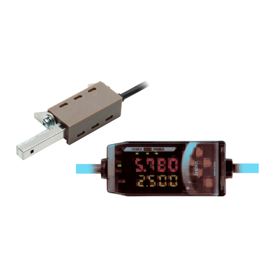
Section 2 Part Names and Functions Part Names and Functions Amplifier Unit Operating Section (*) Display Section (*) (4) Output Cable (3) Connector (two connectors, one on each side) (1) Input Cable (2) Current/voltage switch (on rear side) (5) Power supply indicator (6) Zero Reset indicator (*) Operating and Display Sections (7)ENABLE indicator... - Page 24 Section 2 Part Names and Functions Judgment results/warning states and indicators Hold Output type OPE1 OPE2 OPE3 Other than peak and bottom Standard HIGH PASS hold Warning WARN Peak and bottom hold Warning/ WARN Peak-OK Bottm-OK standard OK: ON when PASS NG: ON whether other than PASS (HIGH or LOW) WARN: ON in warning state Peak-OK: ON when the peak hold result is OK (PASS)
- Page 25 Section 2 Part Names and Functions Sensor Head ■ Sensor Head Sensing section Preamplifier Connector Connect to the Amplifier Unit. Calculating Unit Display (*) Connector (two connectors, one on each side) Connect to the Amplifier Unit. * Display Connection indicator Lit when the Amplifier Unit is connected.
- Page 26 Section 2 Part Names and Functions Interface Unit Display (*) (2) Amplifier Unit connector (1) Connector * Display (3) Power supply indicator (4) Sensor communication indicator (BUSY/ERR) (5) External terminal communication indicator (BUSY/ERR) (1) The communications connector connects the communications cable to the computer.
-
Page 27: Installing The Amplifier Unit
Section 2 Installing the Amplifier Unit Installing the Amplifier Unit Amplifier Units can be easily mounted onto the 35-mm DIN Track. DIN Track (Option) PFP-100N (1 m) PFP-50N (0.5 m) PFP-100N2 (1 m) End Plate (option) PFP-M ■ Installation Hook the connector end of the Amplifier Unit on the DIN Track and press in at the bottom until the Unit locks into place. - Page 28 Section 2 Installing the Amplifier Unit ■ Removal Method Push the Amplifier Unit up and pull out from the connector end. ■ Using the Product in Conformance with CE To use this product in conformance with CE, install the enclosed ferrite core as shown below.
-
Page 29: Installing Sensor Heads
Section 2 Installing Sensor Heads Installing Sensor Heads This section describes how to install Sensor Heads. Sensor Head ■ Installation Fix the Sensor Head using screws. The screws must be tightened with a torque of 0.5 Nm or less. Sensor Head Preamplifier Connector •... - Page 30 Section 2 Installing Sensor Heads Preamplifier ■ Installation Use M3 screws to fix the enclosed Preamplifier mounting bracket. Use the ZX-XBT2 Preamplifier DIN Track Mounting Bracket (order separately) when mounting the Preamplifier onto a DIN Track. Fit one end of the Preamplifier into the bracket. Fit one end into the bracket.
-
Page 31: Mounting On The Mounting Bracket
Section 2 Mounting on the Mounting Bracket Mounting on the Mounting Bracket The following describes how to mount the laser type Smart Sensor (ZX-LD) and static electricity sensor (ZJ-S), or ultrasonic type Smart Sensor (ZX-UD) and static electricity sensor (ZJ-S) onto the exclusive mounting bracket (ZJ-XBU1). Setting the Installation Distance p.41 ■... - Page 32 Section 2 Mounting on the Mounting Bracket Example of mounting the ZX-UD__ ■ Fix the ZX-UD__ onto the mounting bracket (ZJ-XBU1) using the M18 tightening nut. 18.5 mm dia. (+0.5/0) Wave emitting/receiving section Tighten by holding the M18 tightening nut (supplied) between your fingers to secure.
-
Page 33: Connections
Section 2 Connections Connections This section describes how to connect component parts of the Smart Sensor. Before connecting/disconnecting Smart Sensor components, make sure that the power to the Amplifier Unit is turned OFF. The Smart Sensor may malfunction if components are connected or removed while the power is ON. - Page 34 Section 2 Connections Calculating Unit Use a Calculating Unit to connect Amplifier Units when performing communications with two or more Amplifier Units. Up to five Amplifier Units can be connected. Provide power to all connected Amplifier Units. ■ Connection Method Open the connector cover on the Amplifier Unit.
- Page 35 Section 2 Connections ■ Channel Numbers of Amplifier Units The following diagram shows the channel numbers when two or more Amplifier Units are connected. ZJ-SD User’s Manual...
- Page 36 Section 2 Connections Interface Unit Use an Interface Unit to connect a personal computer to the Smart Sensor system. ■ Connection Method Open the connector cover on the Amplifier Unit. Open the connector cover by lifting and sliding it open. Mount the Interface Unit onto the DIN Track.
-
Page 37: Wiring Input/Output Cables
Section 2 Wiring Input/Output Cables Wiring Input/Output Cables The input/output cable has the following wires. Wire the cable correctly. Incorrect wiring may damage the Smart Sensor. Brown (1) 24 VDC power Blue (2) GND White (3) OPE1 judgment output Green (4) OPE2 judgment output Gray (5) OPE3 judgment output... - Page 38 Section 2 Wiring Input/Output Cables I/O Circuit Diagrams Brown 24 VDC Load White OPE1 judgment output Load Green OPE2 judgment output Load Gray OPE3 judgment output 24 VDC GND (0V) Blue Bank shift input Pink Purple Timing input Orange Zero reset input Reset input Current output 4 to 20 mA...
-
Page 39: Section 3 Basic Operation
S e c t i o n 3 BASIC OPERATION Flow of Operation Basic Knowledge for Operation Function Transition Charts Correcting the Measurement Reference Voltage Selecting the Measurement Mode Setting the Installation Distance ZJ-SD User’s Manual... -
Page 40: Flow Of Operation
Section 3 Flow of Operation Flow of Operation Installation and Connection Preparation for Measurement Turn ON the power. Correcting the Measurement p.36 Reference Voltage Select the measurement mode (standard/high-precision). Selecting the p.40 Measurement Mode Setting/Changing Measurement Contents p.52 Setting Number of Samples to Average Making Settings According Setting the Distance Measurement Mode to Your Application... - Page 41 Section 3 Flow of Operation When a Problem Occurs..The Smart Sensor Does Not An Error Message Has Appeared Operate Correctly Error Messages and p.111 p.110 Troubleshooting Countermeasures Want to Know Meanings of Want to Find Contents from Terms Digital Displays p.114 Glossary Quick Reference for...
-
Page 42: Basic Knowledge For Operation
Section 3 Basic Knowledge for Operation Basic Knowledge for Operation Switching Modes The ZJ-SDA has three modes. Use the Mode Switch on the Amplifier Unit to switch between modes. Switch to the desired mode before starting operation. POWER Mode Description Normal operation mode Mode for setting the threshold values Mode for setting measurement conditions... - Page 43 Section 3 Basic Knowledge for Operation Reading Displays The data displayed on the main and sub-displays depends on the currently selected mode. The sensor is already set to the RUN mode before it was shipped from the factory. When the power is turned ON, the model of the Amplifier Unit is displayed on the main display followed by the number of channels.
- Page 44 Section 3 Basic Knowledge for Operation ■ Alphabet Display Format Alphabet characters appear on the main and sub-displays as shown in the following table. Key Operations Use the Control Keys to change the display and set measurement conditions. POWER Control Keys The currently selected mode determines the key functions.
- Page 45 Section 3 Basic Knowledge for Operation Condition Settings Display the target function on the main display and select the desired setting value from the sub-display to set measurement conditions. This section describes how to set measurement conditions, using an example of setting a peak hold as the hold condition.
- Page 46 Section 3 Basic Knowledge for Operation Inputting Numeric Values This section describes how to input numeric values for threshold and output settings. This section describes how to input directly, using an example of inputting the low threshold. Changing the low threshold from "40.000" to "39.000" Moving to the T mode Set the mode switch to T.
-
Page 47: Function Transition Charts
Section 3 Function Transition Charts Function Transition Charts Reading Transition Charts The upper section is the main display and the lower section is the sub-display. Main Display Sub-display RUN Mode Measured value*1 (The main display always shows the measured value.) Threshold*1 Linear output voltage value Linear output current value... - Page 48 Section 3 Function Transition Charts FUN Mode Number of samples Distance Sensor distance Measurement mode*1 Hysteresis width to average measurement mode value p.40 p.52 p.69 p.41 p.43 *1 When the mode is Trigger switched to FUN, the measurement mode p.56 is displayed first.
- Page 49 Section 3 Function Transition Charts Area measurement Timer Hold Area correction p.86 p.53 p.79 p.85 Delay hold Timer time p.81 Sampling period Delay time p.62 p.63 p.63 Initialization Special p.97 This symbol requests you to move to another menu using the LEFT or RIGHT key after pressing the ENT key to confirm the selections.
-
Page 50: Correcting The Measurement Reference Voltage
Section 3 Correcting the Measurement Reference Voltage Correcting the Measurement Reference Voltage More accurate measurement results can be obtained by correcting the potential used as a reference in taking measurements (i.e., resetting zero). As shown below, zero is reset by using a recommended reference detection object that is grounded. - Page 51 Section 3 Correcting the Measurement Reference Voltage Resetting Zero The measurement value is used as a reference value to reset zero when a key operation is performed or an external signal is input. If the reference voltage was previously corrected, the previous correction will be overwritten.
- Page 52 Section 3 Correcting the Measurement Reference Voltage Saving the Zero Reset Level for the Reference Voltage in Zero Reset Memory A setting can be changed to specify whether the zero reset level is saved or cleared when the power supply is turned OFF. Setting Description ON (default)
- Page 53 Section 3 Correcting the Measurement Reference Voltage Moving to the FUN mode and SPCL Set the mode switch to FUN. Use the LEFT and RIGHT keys to display [SPCL] on the main display. Moving to ZRMEM Press the UP or DOWN key. The sub-display flashes.
-
Page 54: Selecting The Measurement Mode
Section 3 Selecting the Measurement Mode Selecting the Measurement Mode The ZJ-SD has two measurement modes, the standard mode and the high-precision mode. Measurement Maximum Display Mode Selection distance range measurement voltage resolution Standard mode STAND ±50 kV 10 V 5 to 100 mm High-precision mode HI-AC... -
Page 55: Setting The Installation Distance
Section 3 Setting the Installation Distance Setting the Installation Distance Set the distance between the static electricity sensor and the workpiece. The electric potential value can be corrected according to the change in the distance between the workpiece and the Sensor Head by performing measurement in combination with a displacement sensor. - Page 56 Section 3 Setting the Installation Distance ■ AUTO mode Enter the current distance "d" between the workpiece and the Sensor Head. Enter the sensor distance value again when the relationship between the static electric sensor and the displacement sensor changes. Displacement sensor Static electricity...
- Page 57 Section 3 Setting the Installation Distance Moving to FUN Mode and DIST Set the mode switch to FUN. Use the LEFT and RIGHT keys to display [DIST] on the main display. Setting the Distance Measurement Mode Press the UP or DOWN key. The sub-display flashes.
- Page 58 Section 3 Setting the Installation Distance MEMO ZJ-SD User’s Manual...
-
Page 59: Section 4 Main Applications And Setting Methods
S e c t i o n 4 MAIN APPLICATIONS AND SETTING METHODS Measuring Sheet Workpieces ZJ-SD User’s Manual... -
Page 60: Measuring Sheet Workpieces
Section 4 Measuring Sheet Workpieces Measuring Sheet Workpieces This section describes how to measure the electric potential of the surface of a workpiece, using a PCB as an example. Flow of Operation ■ Place an actual sensing object in position. Have a reference sample ready beforehand. Setting the Mounting on the Correcting the... - Page 61 Section 4 Measuring Sheet Workpieces Mounting on the Device Mount the Sensor Head on the inspection device. When mounting the sensor, take care not to exert pressure on the Sensor Head and wires. Installing Sensor Heads p.15 Correcting the Measurement Reference Voltage Correct the electric potential that becomes the reference for measuring static electricity.
- Page 62 Section 4 Measuring Sheet Workpieces Setting the Sensor Distance Value Set the distance values of the workpiece and sensor. In the USER mode, the distance values are fixed by the specified distance. • In the AUTO mode, the positional relationship between the displacement sensor and •...
- Page 63 Section 4 Measuring Sheet Workpieces Measuring Reference Samples The difference in the electric potential with the reference sample is measured using position teaching and the measurement result is registered as the HIGH threshold value. The registered value becomes the reference for the threshold value set in step Refer to "Section 5 DETAILED SETTINGS"...
- Page 64 Section 4 Measuring Sheet Workpieces Setting Tolerance Judgment Values Refer to the HIGH threshold registered in step and set the upper and lower limits (HIGH and LOW thresholds) for a PASS (OK) judgment. The judgment result will be output based on the threshold value set here. Output type = standard: "HIGH"...
-
Page 65: Section 5 Detailed Settings
S e c t i o n 5 DETAILED SETTINGS Setting the Number of Samples to Average Using the Hold Functions Entering Threshold Values Linear Output Setting Judgment Output Timing (Timer) Setting the Warning Level (Output type) Using the Area Correction Function Selecting Banks ZJ-SD User’s Manual... -
Page 66: Setting The Number Of Samples To Average
Section 5 Setting the Number of Samples to Average Setting the Number of Samples to Average The average of the measured values obtained based on the preset number of samples can be output. This setting can be used when you want to ignore rapid changes in measured values. Note, however, that if this setting is made, the response time for judgment and linear outputs drops. -
Page 67: Using The Hold Functions
Section 5 Using the Hold Functions Using the Hold Functions The "hold functions" hold data for specific points during the measurement period, such as the minimum and maximum values, and output those values after measurement ends. Flow of Operation ■ (If required) (If required) Selecting the Hold... - Page 68 Section 5 Using the Hold Functions Selection Details PP-H (Peak-to-peak The difference between the minimum and maximum values is held. Select this hold) option mainly to detect vibration. The output changes at the end of the sampling period and is held until the end of the next sampling period. Maximum value Output (maximum value...
- Page 69 Section 5 Using the Hold Functions Moving to the FUN mode and HOLD Set the mode switch to FUN. Use the LEFT and RIGHT keys to display [HOLD] on the main display. Selecting the hold condition Press the UP or DOWN key. The sub-display flashes.
- Page 70 Section 5 Using the Hold Functions Setting the Trigger for Measurement in the Hold Mode Use the UP and DOWN keys to select the desired measurement start conditions. Selection Details TIMNG Enter the trigger for the start of sampling by using the timing input lead. The (Timing input) duration that the timing signal from the timing input lead is ON is the sampling period.
- Page 71 Section 5 Using the Hold Functions Use the UP or DOWN key to select the desired trigger type. There are two trigger types: [TIMNG] and [DIST]. Press the ENT key to confirm the setting. This registers the selected trigger type. ZJ-SD User’s Manual...
- Page 72 Section 5 Using the Hold Functions Setting the Trigger Condition Select the input method for the timing of the start and end of the measurement period. The trigger mode can be selected only when [DIST] is selected as the hold trigger. Selection Details The period in which the displacement sensor measured value is greater than the...
- Page 73 Section 5 Using the Hold Functions • Hysteresis (hysteresis width) Set the hysteresis based on the fluctuations in the measured values around the trigger level. Hysteresis is applied from the start of the sampling period and prevents timing input chattering. •...
- Page 74 Section 5 Using the Hold Functions Use the LEFT or RIGHT key to display [H-LVH] on the main display. H-LVH is not displayed if timing input [TIMNG] is set as the trigger. Press the UP or DOWN key. The leftmost digit of the sub-display flashes. Use the cursor keys to set the desired Moves from one digit to self-trigger level.
- Page 75 Section 5 Using the Hold Functions Setting the hysteresis width (when [DIST] is selected as the hold trigger) Use the LEFT and RIGHT keys to display [H-HYS] on the main display. H-HYS is not displayed if timing input [TIMNG] is set as the trigger.
- Page 76 Section 5 Using the Hold Functions Setting the Delay Time Set the delay time function, for example, to ignore measured values immediately after a hold trigger is detected in order to avoid fluctuation of signals near the sensing object boundary. The delay time (the delay between detection of the trigger and start of sampling) and the sampling period can be set.
- Page 77 Section 5 Using the Hold Functions Setting the delay time Use the LEFT and RIGHT keys to display [H- D-T] on the main display. H-D-T is not displayed if the H-DLY function is set to OFF. Press the UP or DOWN key. The leftmost digit of the sub-display flashes.
-
Page 78: Entering Threshold Values
Section 5 Entering Threshold Values Entering Threshold Values Threshold values are set to determine the range for PASS judgments. Both HIGH and LOW threshold values are set. There are three judgment outputs: "HIGH", "PASS" and "LOW". HIGH threshold Measured value LOW threshold HIGH (ON when the measurement result is... - Page 79 Section 5 Entering Threshold Values Inputting Threshold Values Directly Threshold values can be set by directly inputting numeric values. Direct input is useful when you know the standard values of the static electricity sensor or when you want to fine-tune threshold values after teaching. Moving to the T mode Set the mode switch to T.
- Page 80 Section 5 Entering Threshold Values Position Teaching Measurement is actually performed and the measurement results are used to set threshold values. Position teaching is useful when threshold samples, i.e., with the upper and lower limits, can be obtained beforehand. Teaching point = Teaching point = HIGH threshold LOW threshold...
- Page 81 Section 5 Entering Threshold Values Automatic Teaching When automatic teaching is executed, measurement is performed continuously for the duration that the keys are held down, and the minimum and maximum measurements during that period are set as the threshold values. Automatic teaching is useful when you want to set threshold values by actually starting the device and obtaining real measurements.
- Page 82 Section 5 Entering Threshold Values Setting threshold values Start measurement. Measurement continues for the duration that the ENT and RIGHT keys are held down. [AUTOT] flashes on the sub-display. To end measurement, release the ENT and RIGHT keys. The maximum measured value during the measurement period is set as the HIGH threshold value and the minimum measured value is set as the LOW threshold value.
- Page 83 Section 5 Entering Threshold Values Hysteresis Setting Set the hysteresis width (difference between operation and return points) for the upper and lower limits of judgments if the HIGH, PASS, or LOW judgment is unstable near the sensing boundaries. Hysteresis (hysteresis width) HIGH threshold Measured value Operation point...
-
Page 84: Linear Output
Section 5 Linear Output Linear Output Output Settings (Monitor Focus) "Linear output" refers to the conversion of measurement results to a 3 to 21 mA current output range or a -5 to +5 V voltage output range. The relationship between displayed measured values and output values can be set freely. - Page 85 Section 5 Linear Output This section describes how to set the output range, using an example of current output with a range with the following conversions: 5 kV to 4 mA and 15 kV to 20 mA. Change the values in this example for voltage output as necessary. Output current Output current (mA)
- Page 86 Section 5 Linear Output Use the LEFT and RIGHT keys to display [FOCUS] on the main display. Selecting current (mA) or voltage (V) output Press the UP or DOWN key. The sub-display flashes. Display [mA]. Always select the same output as the current/voltage switch selection on the bottom of the Amplifier Unit.
- Page 87 Section 5 Linear Output Press the ENT key to confirm the setting. This confirms the setting for the first point. The screen for setting the second point is displayed. Setting the second point (B) Use the same procedure as for the first point output current value...
- Page 88 Section 5 Linear Output Correcting Linear Output Values Discrepancies may occur between the linear output current (or voltage) values set on the Amplifier Unit and the actual current (or voltage) values measured due to the conditions for the connected external device or other factors. The linear output correction function can be used to correct this discrepancy.
- Page 89 Section 5 Linear Output Press the ENT key. Use the LEFT and RIGHT keys to display [L- ADJ] on the main display. The units for the monitor focus settings (mA or V) are displayed on the sub-display. Press the ENT key. The display changes to the display for setting the first point (A).
- Page 90 Section 5 Linear Output Setting the second point (B) Use the same procedure as the first point to set the correction value for the second point. Press the ENT key. Confirming setting results If linear output correction has been registered correctly, the sub-display will show [OK].
- Page 91 Section 5 Linear Output Output Settings for Non-measurement The linear output method for when a reset is input can be set. Outputs Selection Judgment outputs Linear output KEEP The measured value immediately before measurement is stopped is held and output. (default) CLAMP All outputs turn OFF.
- Page 92 Section 5 Linear Output Use the LEFT and RIGHT keys to display [RESET] on the main display. Selecting output status at non-measurement Press the UP or DOWN key. The sub-display flashes. Use the UP and DOWN keys to select either KEEP or CLAMP.
-
Page 93: Setting Judgment Output Timing (Timer)
Section 5 Setting Judgment Output Timing (Timer) Setting Judgment Output Timing (Timer) The timing of judgment outputs can be adjusted to match the operation of external devices. Selection Details The judgment is output as soon as the Measured value judgment result has been confirmed. HIGH threshold LOW threshold HIGH output... - Page 94 Section 5 Setting Judgment Output Timing (Timer) Selection Details 1-Sht When the judgment result changes Measured value (One-shot timer) from HIGH to PASS or from LOW to PASS, the PASS output turns ON with a pulse width equivalent to the time set to the timer.
- Page 95 Section 5 Setting Judgment Output Timing (Timer) Press the ENT key to confirm the setting. This registers the setting. If anything other than [OFF] is selected, set the timer time by the following procedure. Setting the timer time (when a timer type other than [OFF] is selected) Use the LEFT and RIGHT keys to display [T-TIM] on the main display.
-
Page 96: Setting The Warning Level (Output Type)
Section 5 Setting the Warning Level (Output type) Setting the Warning Level (Output type) Threshold values (warning level) other than HIGH, PASS or LOW can be set and displayed. Selection Details STAND The warning level is not set. When timer = OFF Measured value (standard) Only the HIGH, PASS or LOW... - Page 97 Section 5 Setting the Warning Level (Output type) Moving to the FUN mode and OUTPT Set the mode switch to FUN. Use the LEFT and RIGHT keys to display [SPCL] on the main display. Press the UP or DOWN key. The sub-display flashes.
- Page 98 Section 5 Setting the Warning Level (Output type) Setting the warning level (only when [WARN] is selected as the output type) Use the LEFT and RIGHT keys to display [WARN] on the main display. Press the UP or DOWN key. The leftmost digit of the sub-display flashes.
-
Page 99: Using The Area Correction Function
Section 5 Using the Area Correction Function Using the Area Correction Function The detection area of the static electricity sensor changes and the average electric potential value inside the detection area is displayed according to the distance between the workpiece and the sensor head. - Page 100 Section 5 Using the Area Correction Function Moving to the FUN mode and AREA Set the mode switch to FUN. Use the LEFT and RIGHT keys to display [AREA] on the main display. Selecting area correction Press the UP or DOWN key. The sub-display flashes.
- Page 101 Section 5 Using the Area Correction Function Set the size of the area. Moves from one digit to Enter the size of the area to be sensed (mm dia.) as the another. [SIZE]. Changes the numeric value. Press the ENT key to confirm the setting. This registers the setting.
-
Page 102: Selecting Banks
Section 5 Selecting Banks Selecting Banks Up to four setting patterns can be stored in the ZJ-SD, and a set of these patterns is called a "bank." • Four banks can be selected. • Banks are switched by external input leads or the amplifier (bank switching in the FUN mode [BANK]). - Page 103 Section 5 Selecting Banks Selecting banks Turn (10) Bank input 1 and (12) Bank input 2 ON/OFF. Banks are specified by the combination of the ON/OFF settings of these two inputs. Bank No. and External Input Lead External input lead Bank No.
- Page 104 Section 5 Selecting Banks ■ Procedure for switching banks from an amplifier Moving to the FUN mode and BANK Set the mode switch to FUN. Use the LEFT and RIGHT keys to display [BANK] on the main display. Selecting banks Press the UP or DOWN key.
- Page 105 S e c t i o n 6 AUXILIARY FUNCTIONS Changing the Number of Display Digits Reversing the Display Adjusting Display Brightness (ECO Display) Key Lock Function Initializing Setting Data Changing Display Scales Comparing Measured Values (Differentiation Function) 105 ZJ-SD User’s Manual...
- Page 106 Section 6 Changing the Number of Display Digits Changing the Number of Display Digits Select the number of digits (0 to 5) for the main and sub-displays in the RUN mode. The default setting is five digits. When four or less digits are set, the digits are disabled from the rightmost digit first.
- Page 107 Section 6 Reversing the Display Reversing the Display The main and sub-digital displays can be reversed, i.e., be turned upside down. Cursor key operation also is reversed. This function is useful when mounting the Amplifier Unit upside down on a device. OFF (not reversed) ON (reversed) DOWN...
- Page 108 Section 6 Reversing the Display Selecting whether or not to reverse display Press the UP or DOWN key. The sub-display flashes. Select either [OFF] or [ON]. OFF: Display not reversed (default) ON: Display reversed Press the ENT key to confirm the setting. This registers the setting.
- Page 109 Section 6 Adjusting Display Brightness (ECO Display) Adjusting Display Brightness (ECO Display) When the ECO display function is used, the digital displays darken, reducing current consumption. Moving to FUN and SPCL Set the mode switch to FUN. Use the LEFT and RIGHT keys to display [SPCL] on the main display.
- Page 110 Section 6 Key Lock Function Key Lock Function The key lock function disables all Amplifier Unit keys. Once the keys have been disabled, no key input is accepted until the lock is canceled. This function is useful to prevent inadvertent changes to settings.
- Page 111 Section 6 Initializing Setting Data Initializing Setting Data Initialization resets the settings of all banks or the currently selected bank to their default values. • There are two [INIT] options, [ALL] and [NOW]. [ALL]: This initializes all banks (0 to 3). [NOW]: This initializes the currently selected bank.
- Page 112 Section 6 Initializing Setting Data Moving to the FUN mode and INIT Set the mode switch to FUN. Use the LEFT and RIGHT keys to display [INIT] on the main display. Selecting initialization of all banks/initialization of currently selected bank Press the UP or DOWN key.
- Page 113 Section 6 Changing Display Scales Changing Display Scales Change the display scale when you want to display a value on the main display that is different from the actual measured value. Place an actual sensing object in position. Two setting methods are available: one-point and two-point scaling. •...
- Page 114 Section 6 Changing Display Scales Executing scaling Press the UP or DOWN key. The sub-display flashes. Use the UP and DOWN keys to display [ON]. Press the ENT key to confirm the setting. The sub-display indicates [P1SCL]. Place the sensing object at the position where the display value change is required.
- Page 115 Section 6 Changing Display Scales Use the LEFT and RIGHT keys to change the decimal point position, if necessary. Press the ENT key to confirm the setting. The inverted display settings appear on the sub-display. Selecting inverted display Use the UP and DOWN keys to select the inverted display function.
- Page 116 Section 6 Changing Display Scales Confirming completion of scaling If scaling has been completed correctly, the display indicates [OK]. If scaling was not possible, the display indicates [NG]. Check that the ENABLE indicator is lit, and execute scaling again. ZJ-SD User’s Manual...
- Page 117 Section 6 Changing Display Scales Two-point Scaling Measurement is performed at two points and offset values are set for those measured values. Both an overall offset can be set and the range can be changed. Displayed value (kV) Actual measured value (kV) Allow at least 1 kV between the two points to specify.
- Page 118 Section 6 Changing Display Scales Press any cursor key. The current measured value is displayed on the main display. The leftmost digit of the sub-display flashes. Use the cursor keys to set the offset for the Moves from one digit to measured value.
- Page 119 Section 6 Comparing Measured Values (Differentiation Function) Comparing Measured Values (Differentiation Function) Use the differentiation function to detect only sudden changes in the measured values that occur during very short periods of time. The differentiation function detects changes between the present value and the measured value that was active just before the comparing pitch.
- Page 120 Section 6 Comparing Measured Values (Differentiation Function) Moving to DIFF Press the UP or DOWN key. The sub-display flashes. Use the UP and DOWN keys to display [SET] or [ALL]. Press the ENT key. Use the LEFT and RIGHT keys to display [DIFF] on the main display.
- Page 121 Section 6 Comparing Measured Values (Differentiation Function) Setting the differentiation cycle Use the LEFT and RIGHT keys to display [D- CYC] on the main display. [D-CYC] is not displayed if [DIFF] is set to [OFF]. Press the UP or DOWN key. The leftmost digit of the sub-display flashes.
- Page 122 Section 6 Comparing Measured Values (Differentiation Function) MEMO ZJ-SD User’s Manual...
- Page 123 S e c t i o n 7 APPENDICES Troubleshooting Error Messages and Countermeasures Q&A Glossary Specifications and Dimensions Communicating with the Static Electricity Smart Monitor via the Interface Unit Characteristic Data Quick Reference for Displays INDEX ZJ-SD User’s Manual...
- Page 124 Section 7 Troubleshooting Troubleshooting This section describes countermeasures for temporary hardware problems. Check the malfunction in this section before sending the hardware for repair. Problem Probable cause and possible countermeasure Pages Device restarts during operation. • Is the power supply device connected correctly? p.23 •...
- Page 125 Section 7 Error Messages and Countermeasures Error Messages and Countermeasures This section outlines the error messages displayed on the main display and the countermeasures for those messages. [Errors that occur during regular measurement] Display Error Countermeasure Pages E-SHT One or all of the judgment outputs is short- Correct short-circuiting of short-circuited loads.
- Page 126 Section 7 Error Messages and Countermeasures [Errors that occur when an adjacent distance sensor is used] Display Error Countermeasure Pages E-DIS The acquired distance data is in error. • Check that the connected distance sensor is measuring correctly. p.17 • Check the connection between the Amplifier Unit p.85 and Sensor Head.
- Page 127 Section 7 Q&A Q&A Question Answer What types of Interface Unit can be used? A ZJ-SF11 is required. A ZX-SF11 compatible with the ZX series cannot be used. Why does an error occur and settings cannot be made Threshold values cannot be set using teaching or by direct when teaching or directly inputting threshold values? input if the following condition is not met: •...
- Page 128 Section 7 Glossary Glossary Term Explanation Response time Response time is the time from when the sensor measures a charged amount to when the value is output (either as linear output or judgment output). The response time changes depending on the settings for the number of samples to average and calculations.
- Page 129 Section 7 Specifications and Dimensions Specifications and Dimensions Amplifier Unit ZJ-SDA11 (Unit: mm) 67.3 Round vinyl insulated cable Round vinyl insulated cable 5.2 mm dia., 10-wire 5.1 mm dia., 9-wire 36.8 (conductor cross-sectional area: (conductor cross-sectional area: 0.09 mm / insulator diameter: 0.7 mm) 0.09 mm / insulator diameter: 0.7 mm) Standard length: 2 m...
- Page 130 Section 7 Specifications and Dimensions Item ZJ-SDA11 Measurement cycle 1 ms Possible settings for 1, 2, 4, 8, 16, 32, 64, 128, 256, 512, 1024 times number of samples to average (*1) Temperature Static Electricity Sensor Head: 0.01%F.S./°C characteristics Linear output (*2) At current output: 4 to 20 mA/F.S, maximum load resistance 300 Ω...
- Page 131 Section 7 Specifications and Dimensions Sensor Head ZJ-SD100 Sensor Head • · Angle 1 · Angle 2 2-3.2 dia. mounting holes (66.6) (39.5) 27.1 33.5 39.2 Sensing section Mount hole dimensions 2−M3 20±0.1 Preamplifier • · Preamplifier mounting bracket · Preamplifier (common to all models) (91) (16.4) Round vinyl insulated cable...
- Page 132 Section 7 Specifications and Dimensions Item ZJ-SD100 Applicable Amplifier Unit ZJ-SDA11 Measurement distance 5 to 100 mm Max. measurement voltage (*1) Standard mode: ±50 KV, high-precision mode: ±5 KV Resolution (*2) Standard mode: 10 KV, high-precision mode: 1 KV Linearity (*3) ±5%FS (*4) Ambient temperature Operating/storage: 0 to +50°C...
- Page 133 Section 7 Specifications and Dimensions Sensor Head mounting bracket at distance correction ZJ-XBU1 (78.5) 62±0.1 38.5±0.1 16±0.1 32±0.1 15±0.1 30±0.1 20±0.1 15±0.1 38.5±0.1 62±0.1 ZJ-SD User’s Manual...
- Page 134 Section 7 Specifications and Dimensions Dimensions when mounting bracket is mounted on sensor · When ZJ-S and ZX-LD are mounted 95.3 62±0.2 ±0.2 16.5 23.5± ZX-LD100 Sensing Optical axis 26.4 section ZJ-SD 23.5± ±0.2 ±0.2 · When ZJ-S and ZX-UD are mounted (110) 62±0.2 47±0.2...
- Page 135 Section 7 Specifications and Dimensions Calculating Unit ZX-CAL2 (unit: mm) 24.9 15.1 54.9 36.7 Item ZX-CAL2 Applicable Amplifier Units ZX series, ZJ-S series Current consumption 12 mA or less (supplied from the Amplifier Unit) Ambient temperature Operating: 0 to +50°C, Storage: -15 to +60°C (with no icing or condensation) Ambient humidity Operating and storage: 35% to 85% (with no condensation) Connection method...
- Page 136 Section 7 Specifications and Dimensions Interface Unit ZJ-SF11 (unit: mm) 67.3 Round vinyl insulated cable 5.2 mm dia. Standard length: 0.5 m ■ Connector Pin Arrangement and Connection Example with Personal Computer ZJ-SF11 side Personal computer side (PC/AT compatible) Connect the ZJ-SF11 and the personal computer using a D-sub 9-pin (female-female) Pin No.
- Page 137 Section 7 Specifications and Dimensions Item ZJ-SF11 Power supply voltage 12 to 24 VDC ±10%, Ripple (p-p) 10% max. Supplied from Amplifier Unit Current consumption At 24 V power supply voltage, 60 mA max. (excluding Amplifier Unit current consumption and output current) Connectable Amplifier Units ZJ-S series, ZX series Number of connectable Amplifier...
- Page 138 Connect the Interface Unit to the Amplifier Unit. Use of a calculating unit (ZX-CAL2) allows connection of up to five Amplifier Units. If you want to connect different types of Amplifier Units, such as ZJ-SDA11 and ZX-E series, contact your OMRON representative. Connection Method p.22 ZJ-SD...
- Page 139 Section 7 Communicating with the Static Electricity Smart Monitor via the Interface Unit Turn ON the power supply to the Amplifier Unit. Power indicator When the Amplifier Unit is powered ON, the Sensor communication Interface Unit will also be powered ON. indicator (BUSY/ERR) When the ERR indicators for the Interface Unit’s sensor...
- Page 140 Section 7 Characteristic Data Characteristic Data Measurement Voltage-Linearity Characteristics 1.00 0.80 0.60 0.40 0.20 0.00 -0.20 -0.40 -0.60 -0.80 -1.00 Measurement voltage (kV) Sensing object: Charging plate (150 x 150 mm, 20 pF) Measuring distance: 10 mm Measurement mode: standard Measuring Distance-Error Characteristics -0.2 -0.4...
- Page 141 Section 7 Quick Reference for Displays Quick Reference for Displays Using the Quick Reference Items in the Display column followed by an asterisk appear on the sub-display. All other items appear on the main display. Display Details Pages 1-SHT Timer/One-shot timer p.80 A20mA The meaning of this display item depends on the selected functions.
- Page 142 Section 7 Quick Reference for Displays Display Details Pages D-CYC Differentiation function/Differentiation cycle count p.107 D-FWD Display direction for measured values when scaling function is used p.101 (display not inverted) D-INV Display direction for measured values when scaling function is used p.101 (display inverted) DIFF...
- Page 143 Section 7 Quick Reference for Displays Display Details Pages P1SCL Scaling/First point scaling p.100 P2SCL Scaling/Second point scaling p.103 PB-H Hold/Peak and bottom hold p.53 Hold/Peak hold p.53 PP-H Hold/Peak-to-peak hold p.53 RESET Output settings for non-measurement p.77 RESET RUN or T mode/Resetting input p.23 Hold/Sample hold p.53...
- Page 144 Section 7 Quick Reference for Displays MEMO ZJ-SD User’s Manual...
- Page 145 Section 7 INDEX INDEX ENABLE indicator Error messages Adjusting display brightness Alphabet display format Amplifier Unit FIX mode Specifications Flow of Operation Dimensions FUN Mode Part names 7, 9 Display Contents Area correction function Function transition Outline Function Transition Charts AUTO mode Automatic teaching Glossary...
- Page 146 Section 7 INDEX Part names Response time 52, 114 Linear GND wire Reversed display Linear output RUN Mode Correcting Output Values Display Contents Linear output wire Function transition Outline Main Display Mask hold Sample hold Measured value Sampling period Mode Self-down trigger Switch Self-up trigger...
- Page 147 Section 7 INDEX Zero reset Indicator ZJ-SD User’s Manual...
- Page 148 Section 7 INDEX MEMO ZJ-SD User’s Manual...
- Page 149 Section 7 INDEX MEMO ZJ-SD User’s Manual...
-
Page 150: Zj-Sd
Section 7 Revision History Revision History A manual revision code appears as a suffix to the catalog number at the bottom of the front and back covers of this manual. Cat. No. Z237-E1-02 Revision code Revision code Date Revised contents December 2005 Original production November 2006 Dimensions changed and reference potential compensation function added. - Page 151 Germany Tel: (49)7032-811-0/Fax: (49)7032-811-199 OMRON ELECTRONICS LLC 1 East Commerce Drive, Schaumburg, IL 60173 U.S.A. Tel: (1)847-843-7900/Fax: (1)847-843-8568 OMRON ASIA PACIFIC PTE. LTD. 83 Clemenceau Avenue, #11-01, UE Square, 239920 Singapore Tel: (65)6835-3011/Fax: (65)6835-2711 OMRON (CHINA) CO., LTD. Room 2211, Bank of China Tower,...
Need help?
Do you have a question about the ZJ-SD Series and is the answer not in the manual?
Questions and answers