Table of Contents
Advertisement
Advertisement
Table of Contents

Related Manuals for Omron ZFV - V2.0


Summary of Contents for Omron ZFV - V2.0
- Page 1 Cat. No. Z207-E1-03 ZFV Series (Ver 2.0) Smart Sensors USER’S MANUAL...
- Page 2 APPLICATION CONSIDERATIONS (Please read first) INTRODUCTION FEATURES SECTION 1 INSTALLATION & CONNECTION SECTION 2 SETUP SECTION 3 APPENDIX SECTION 4 User’s Manual Smart Sensors with Ultra-high-Speed CCD Camera ZFV Series...
-
Page 3: Chara/Chara 1, Chara
The following are some examples of applications for which particular attention must be given. This is not intended to be an exhaustive list of all possible uses of the products, nor is it intended to imply that the uses listed may be suitable for the products: •... -
Page 4: Performance Data
FOR THE INTENDED USE WITHIN THE OVERALL EQUIPMENT OR SYSTEM. PERFORMANCE DATA Performance data given in this document is provided as a guide for the user in determining suitability and does not constitute a warranty. It may represent the result of OMRON’s test conditions, and the users must correlate it to actual application requirements. -
Page 5: Precautions For Safe Use
• Do not use the product in environments where it can be exposed to inflammable/ explosive gas. • Install the Amplifier Unit in such a way that the ventilation holes are not blocked. • To secure the safety of operation and maintenance, do not install the product close to high-voltage devices and power devices. -
Page 6: Precautions For Correct Use
• When using a commercially available switching regulator, make sure that the FG ter- minal is grounded. • If surge currents are present in the power lines, connect surge absorbers that suit the operating environment. • Before turning ON the power after the product is connected, make sure that the power supply voltage is correct, there are no incorrect connections (e.g. - Page 7 LCD monitor of the Amplifier Unit. (6) Ventilation Film • Do not peel off or probe the ventilation film with a sharp-pointed object. If you so, the specifications of the protective structure may no longer be satisfied. • Do not block the ventilation film. Doing so might cause the front panel to be con- densed.
-
Page 8: Editor's Note
Setting Banks Overview Setting Banks Cross-header The ZFV Series can hold up to eight sets of settings. These settings can be switched Overview of the externally when changing the device setup A set of these settings is called a “bank.”... - Page 9 Indicates points that are important to ensure full product performance, such as operational precautions and application procedures. Indicates pages where related information can be found. Indicates information helpful in operation. Indicates functions that can be set only when the setup menu has been switched to EXP menu. User’s Manual...
-
Page 10: Table Of Contents
Page Format CONTENTS SECTION 1 FEATURES ZFV Smart sensor Features Basic Configuration Part Names and Functions SECTION 2 INSTALLATION & CONNECTION About Installation and Connection Amplifier Unit Attaching the ferrite core Installing the Amplifier Unit Gang mounting About the I/O cable... - Page 11 Clearing banks Setting the bank switching method Setting the System Environment Adjusting the measurement speed Selecting the measurement timing Selecting the teaching mode from an external device Setting/canceling the “Eco” mode Initializing setup data Initializing measurement data Checking the version...
- Page 12 When Gang-mounting Amplifier Units Gang-mounting example Rules of gang-mounting Data route Teaching process when gang-mounting Integrating judgment output Restrictions when gang-mounting old and new amplifier units Specifications and External Dimensions Sensor Head Amplifier Unit Panel Mount Adapters Control Link Unit...
- Page 13 Introduction CONTENTS MEMO User’s Manual...
-
Page 14: Section 1 Features
Section 1 FEATURES ZFV Smart sensor Features Basic Configuration Part Names and Functions User’s Manual... -
Page 15: Zfv Smart Sensor Features
Sensor Head takes up little installation space. (2) Easy Installation and Adjustment The range that can be sensed by Sensor Head can be confirmed by the guide light. So, the Sensor Head can be installed by viewing the position of the guide light and its focus. - Page 16 Section 1 ZFV Smart sensor Features (3) Business Card-size Amplifier Unit • The Amplifier Unit is designed to be compact so that it can be installed at a wide range of sites. Specifications and External Dimensions p.95 • Outstanding operate ease has been achieved by a 1.8″color LCD motor, an industry- first icon-based menu, and simple key layout.
-
Page 17: Basic Configuration
Right Wrong Wrong • The maximum number of Amplifier Units that can be connected is five regardless of the number of connected Sensor Heads.Six or more Amplifier Units cannot be connected. • Provide power to all gang-mounted Amplifier Units. User’s Manual... - Page 18 When the TRIG signal is input from a single specified Amplifier Unit, the connected Amplifier Unit starts sensing immediately. The result of sensing is integrated on the Amplifier Unit to which the TRIG signal was input, and is output as a total judgment result.
-
Page 19: Part Names And Functions
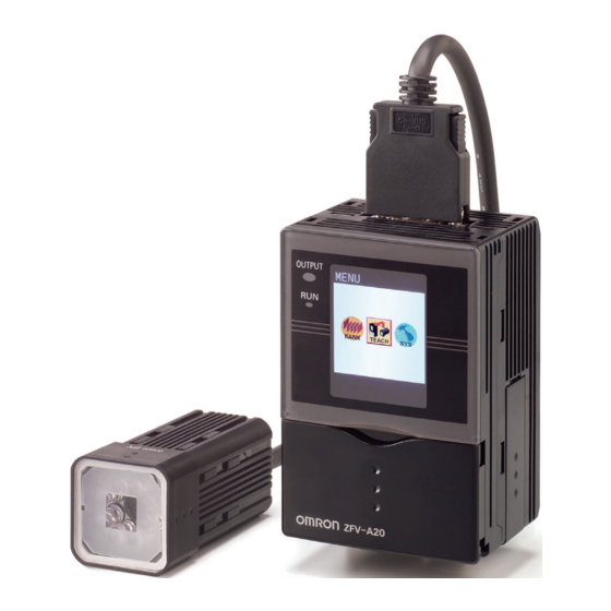
Section 1 Part Names and Functions Part Names and Functions The following describes the names and functions of parts on the Amplifier Unit and Sensor Head. ■ Amplifier Unit (7) Sensor Head connector (1) OUTPUT indicator (2) RUN indicator (6) LCD monitor... - Page 20 Sensor Head connector This connector connects the Sensor Head. Coupler This connector is used to connect two or more Amplifier Units. It is located on both sides of the Amplifier Unit. I/O Cable The I/O cable connects the Amplifier Unit to the power supply and external devices, such as timing sensors or programmable controllers.
-
Page 21: Sensor Head
This connector is connected to the Amplifier Unit. Sensor Head mounting fixture This fixture is for mounting the Sensor Head. This fixture can be mounted on all of the four mounting surfaces. Focus adjustment control This control is used for adjusting the focus of the image. -
Page 22: Section 2 Installation & Connection
Section 2 INSTALLATION & CONNECTION About Installation and Connection Amplifier Unit Attaching the ferrite core Installing the Amplifier Unit Gang mounting About the I/O cable Timing charts Sensor Head Attaching the ferrite core Installing the mounting fixture Installing the Sensor Head Connecting the Sensor Head User’s Manual... -
Page 23: About Installation And Connection
About Installation and Connection About Installation and Connection ■ Checking the installation environment Read “Precautions for Safe Use” at the beginning of this manual, and check the instal- lation environment. ■ Checking the installation site Read “Precautions for Correct Use” at the beginning of this manual, and check the installation site. -
Page 24: Amplifier Unit
This section describes installation of the Amplifier Unit, and connection of the I/O cable. Before connecting/disconnecting peripheral devices, make sure that the Smart Sensor is turned OFF. The Smart Sensor may break down if the Smart Sensor is connected or disconnected while the power is ON. -
Page 25: Installation Procedure
Push down until you hear it snap into place. Always hook the connector end of the Amplifier Unit on the DIN track first. Hooking the I/O cable end on the DIN track first may impair the mounting strength of the DIN track attachment. - Page 26 Section 2 Amplifier Unit ■ Mounting on a panel The Panel Mount Adapters (sold separately ZS-XPM1) can be used to mount the Amplifier Unit on a panel. Panel Mount Adapters p.100 Push out the Amplifier Unit from the rear of Panel the panel towards the front.
- Page 27 Install the Amplifier Unit with Mount Adapters Panel attached onto the panel from the front. Take care not to pinch the I/O cable. Hook the hooks of the mounting fixture onto the two holes of the smaller Mount Adapters Mounting fixture and tighten the screws.
-
Page 28: Gang Mounting
Open the connector cover on the Amplifier Unit. Controller Link Unit Slide the cover to remove. Insert the Controller Link Unit into the connector on the Amplifier Unit. Slide the Amplifier Unit, and insert into the connector on the Controller Link Unit. User’s Manual... - Page 29 Link Unit Slide the Controller Link Unit and remove from the connector on the Amplifier Unit. Install the cover on the coupler of the Amplifier Unit. Pull the hook on the I/O cable end downwards. Lift up the Amplifier Unit from the I/O cable end, and remove it from the DIN track.
- Page 30 Install the Amplifier Unit on the DIN track. p.27 When mounting on a panel, be sure to install the DIN track on the rear side of the Amplifier Unit for support. Push out the Amplifier Unit from the rear of the panel towards the front.
- Page 31 Install the long Mount Adapters on the two Panel Mount Adapters holes on the small Mount Adapter. Install the long Mount Adapters only on both sides of gang-mounted Amplifier Units. Panel Mount Adapters Install the Amplifier Unit with Mount Adapters Panel attached onto the panel from the front.
-
Page 32: About The I/O Cable
* : Enabled only in the RUN mode Power supply This connects the power supply. Supply power from a DC power supply unit that has a countermeasure (safety ultra- low voltage circuit) built-in for preventing high voltages from occurring. Recommended power supply unit p.16 Wire the power supply separately from other devices. - Page 33 Selecting the teaching mode from an external device p.61 TRIG (measurement trigger input) There are two measurement modes, synchronous measurement and continuous measurement. Which mode of measurement is to be performed in is selected in the menu. Selecting the measurement timing p.61...
- Page 34 Section 2 Amplifier Unit ● PNP output type (ZFV-A15/A25) Brown Power supply (24VDC) Yellow TEACH Pink TRIG Gray BANK1 Green BANK2 BANK3 Blue GND(0V) Light blue ERROR 24VDC Orange ENABLE Load Black OUTPUT Load Load User’s Manual...
-
Page 35: Timing Charts
• The minimum ON width of the TRIG signal is 1 ms. • The OUTPUT signal is held until the next measurement result is updated. Note, however, that when one-shot output is currently set, the OUTPUT signal is held for the preset time. - Page 36 (3) Make sure that the workpiece to be taught is in the teaching area. (4) Input the TRIG signal from the outside. (5) The ENABLE signal turns ON after teaching is completed. At this timing, check the state of the ERROR signal.
- Page 37 (1) Turn the TEACH signal ON from the outside. (2) Confirm that the ENABLE signal has turned OFF. (3) Input the TRIG signal at the timing for measuring the workpiece to be taught. (4) Repeat the input in step (3) six times. (Trigger inputs from the seventh time onwards are ignored.)
-
Page 38: Sensor Head
Sensor Head This section describes how to install and connect the Sensor Head. Attaching the ferrite core Attach the ferrite core (provided with the Smart Sensor) to the connector side of the Sensor Head. Ferrite core Installing the mounting fixture Attach the mounting fixture (provided with the Smart Sensor) to the side of the Sensor Head. -
Page 39: Installing The Sensor Head
This section describes how to install the Sensor Head. The detection range of the Sensor Head can be confirmed by the guide light. Install so that the part to be inspected is inside the frame formed by the guide light. - Page 40 Workpiece Setting distance L Detection range H ● About installation for reflective workpieces Install the Sensor Head at an angle to prevent mirror reflection light from being picked up by the sensor. Mirror reflec- tion light Guide light User’s Manual...
-
Page 41: Connecting The Sensor Head
Before turning the focus adjustment control slightly to the left and right, make sure that the guide light is not at the upper or lower limit positions. The focus adjustment control is a multi-turn variable resistor. However, the control stops turning at the upper or lower limit positions. Do not exert unnecessary force to turn the control at the upper or lower limit positions as this might damage the control. -
Page 42: Section 3 Setup
Performing Measurement Setting Banks Setting the System Environment Adjusting the measurement speed Selecting the measurement timing Selecting the teaching mode from an external device Setting/canceling the “Eco” mode Initializing setup data Initializing measurement data Checking the version Changing image capture timing on teaching screen... -
Page 43: Setting Flow
Set measurement conditions are saved to the amplifier unit "when external TEACH signal teaching is suc- cessful" or "when switched to RUN mode." When the TEACH key is pressed from the teaching screen to teach, contents will not be saved unless switched to RUN mode once.Changed contents, including teach- ing results, are cleared when switching off without saving. - Page 44 Adjusting the measurement speed p.61 Setting Up the System Setting Up the System Selecting the measurement timing p.61 Environment Environment Selecting the teaching mode from an external device p.61 Setting/canceling the “Eco” mode p.62 Changing the Input/Output Changing the Input/Output p.65...
-
Page 45: About Setup
About Setup About Setup Basic Knowledge for Operation ■ Switching Modes There are 3 operating modes as follows. Switch to the desired mode before you start operation. To switch the operating mode, use the mode switch. Mode Description MENU mode This mode is for executing teaching or setting up the measurement conditions. -
Page 46: Key Operations
Section 3 About Setup ■ Displays and Key Operations Make setups using the control keys while viewing the menus and the image displayed on the LCD monitor. ● Display The details that are displayed differ according to the operating mode. -
Page 47: List Of Setting Items In Menu Mode
AVERAGE AVERAGE, DEVIATION [ITEM]:[AREA] p.74 COLOR WHITE BLACK, WHITE p.74 BINARY 0 to 255 [ITEM]:[WIDTH] p.75 COLOR WHITE BLACK, WHITE p.75 DIRECTION (*2)The display details of items from [CUSTOM] onwards differ according to the item selected at [ITEM]. User’s Manual... - Page 48 DELMIT CR, LF, CR+LF p.62 ALL CLEAR p.62 MEAS CLEAR p.63 VERSION LINKSET (*3) p.69 TRIG I/O, LINK p.70 HEAD USE, NOT USE p.70 OUTPUT EACH ALL, EACH (*3)This menu is displayed only when Amplifier Units are gang-mounted. User’s Manual...
-
Page 49: Executing Teaching
Executing Teaching Execute teaching, and set the measurement conditions. Project the image to be used as the accepted image as the details set in teaching are used as the reference in judgment. Teaching Flow There are two ways of executing teaching, by key operation and by external signals. - Page 50 TEACH/SEARCH ABCDE 1.ITEM 2.MOVE 3.SIZE When changing the teaching area positioning or size, select [MOVE] or [SIZE] from screen 3 then adjust accordingly. [MOVE] [SIZE] Move the area to the position for teach- Adjust the area size for teaching then ing then press the SET key.
- Page 51 Executing Teaching ■ Teaching Key Operations and Screen Transition FUN mode top screen ● Teaching execution ● Setting of teaching conditions Setting the teaching details Moving the position of the teaching area Changing the size of the teaching area User’s Manual...
-
Page 52: Types Of Teaching
Section 3 Executing Teaching Types of Teaching Select the type of teaching according to the detection content. The details that are displayed differ according to the model of Amplifier Unit that you are using. Detection Content Type of Teaching to Select... - Page 53 Changing the search area p.81 BRIGHT Select this item to detect brightness (density) or scratches/ Detection of dirt on plain workpieces. Set the teaching area to the desired scratches/dirt in part of the workpiece to detect brightness in, and execute sheets teaching.
- Page 54 Example of Application WIDTH * Select this item to detect width or interval. Detection of lead Set the teaching area to the part of the workpiece to perform width on capacitors or measurement in, and execute teaching. other electronic com-...
- Page 55 (Be sure, however, to set to an area having a plain background.) If an area very close to the character string without any margin is set, the sensor will not be able to track any shift in the printing position.
-
Page 56: Adjusting Threshold Values
Range Details of Adjustment Correlation value 0 to 100 This is the lower limit of the correlation value with the teaching model This value or above is judged as OK. ■ BRIGHT ● Switch to ADJ Mode. ● Adjustment of average density value ●... - Page 57 Range Details of Adjustment Area value 0 to 999 This is the area in which OK is judged when the area value during teaching is taken to be 100%. ■ WIDTH ● Switch to ADJ Mode. ● Adjustment of edge width ●...
- Page 58 0 to 468 Amount of shift from reference position Edge level 0 to 100 This is the level of change in density judged to be an edge. Adjust this level when measurement is unstable. p.56 ■ COUNT ● Switch to ADJ Mode.
- Page 59 Setting item Range Details of Adjustment Density distribution 0 to 100 This is the value that is judged as OK when the density deviation value value during teaching is taken to be 100%. ■ CHARA 2 ● Switch to ADJ Mode.
-
Page 60: Performing Measurement
The measurement time differs according to the type of display image. The measurement time for “only image display” is the fastest. The number in parentheses ( ) serves as a guideline when “only image display” is taken as the reference. -
Page 61: Setting Banks
Section 3 Setting Banks Setting Banks The ZFV Series can hold up to eight sets of settings. These settings can be switched externally when changing the device setup. A set of these settings is called a “bank.” Switching banks BANK 1 is selected as the default. BANK 2 and 8 are also available. -
Page 62: Setting The System Environment Adjusting The Measurement Speed
MENU Mode-[SYS1]-[TEACH TYPE] Setting Description STATIONARY (default) Teaching is performed with the workpiece in a stationary state. Input of the exter- nal trigger input is required for teaching. MOVING The teaching is performed with the moving workpiece. Select this teaching mode only when the workpiece cannot be stopped. -
Page 63: Setting/Canceling The "Eco" Mode
Setting the System Environment Setting/canceling the “Eco” mode Whether or not to darken the screen when a preset time has passed without any operation. We recommend setting this mode to [ON] to prevent the brightness of the LCD screen from being impaired. -
Page 64: Checking The Version
Section 3 Setting the System Environment Checking the version Displays the type of Sensor Head, type of Amplifier Unit and system version information of the software. MENU Mode-[SYS2]-[VERSION] Changing image capture timing on teaching screen Select status of image to be displayed in the teaching screen. -
Page 65: Setting Communications Environment
CompoWay/F. NORMAL Select when connected to the ZS-DSU for communication without external device procedures. For details on command formats, refer to the ZS-DSU manual, "Communication Command Reference" (provided separately). Set the same communications protocol when gang-mounted with ZS-DSU. [DELMIT] A delimiter can be set when there are no communication protocol procedures. -
Page 66: Changing The Input/Output Conditions Selecting The On Conditions
Section 3 Changing the Input/output Conditions Changing the Input/output Conditions Selecting the ON conditions Set whether to turn the OUTPUT signal ON when OK is judged or when NG is judged. MENU Mode-[SYS2]-[OUTPUT]-[ON STATUS] Setting Description OK ON Turns the OUTPUT signal ON when OK is judged. -
Page 67: Setting The On Delay Time
One-shot output is not performed. One-shot output is performed. When one-shot output is set to [ON], the OFF delay time setting is disabled. ■ Setting the one-shot output time OUTPUT turns ON for the preset time from when the OUTPUT signal turns ON. -
Page 68: Setting The Off Delay Time
Section 3 Changing the Input/output Conditions Setting the OFF delay time Set this item to delay the timing that the OUTPUT signal turns OFF. OUTPUT ON at OK judgment in continuous measurement Judged as NG Judged as OK Judged as NG... -
Page 69: I/O Monitor Function
Displays ON/OFF status of ERROR signal. (0:OFF, 1:ON) Put the cursor on BANK, OUTPUT, ENABLE then press the SET button key to switch between "0" and "1". The external device operations can be checked by switching output OFF/ON when the actural measurements are not being performed. -
Page 70: Settings During Application Extended Connection
Set whether or not to input the TRIG signal to an Amplifier Unit. MENU Mode-[SYS2]-[LINKSET]-[TRIG] Setting Description I/O (default value) Set to only the Amplifier Unit to which the TRIG signal is to be input. LINK Synchronizes to the TRIG signal from the Amplifier Unit gang-mounted on the right side. User’s Manual... -
Page 71: Setting The Presence Of Sensor Head
Measurement is performed from the image transferred from the Sensor Head gang-mounted on the right side. Setting output content Set the output content of the measurement result. This item is displayed only the Amplifier Unit whose [TRIG/TRIG] setting is set to [I/O]. MENU Mode-[SYS2]-[LINKSET]-[OUTPUT] Setting Description The measurement results of all gang-mounted Amplifier Units are integrated, and output as an overall judgment result. -
Page 72: Customizing Measurement Conditions
Section 3 Customizing Measurement conditions Customizing Measurement conditions The display items from [CUSTM] onwards differ according to the teaching type set at [ITEM]. Common items ■ Adjusting light emission Adjust the intensity of the light emitted from Sensor Head. The light intensity of each adjusted section is displayed as a 4-digit number. -
Page 73: Pattern/Search, Match
MENU Mode-[CUSTM]-[SEARCH AREA] ■ Setting the rotation range of a workpiece This item is displayed only when [SEARCH] is set. Set this item when even a tilted workpiece is to be set as a non-defective item. MENU Mode-[CUSTM]-[ROTATION] Setting Description ±10°... -
Page 74: Bright
Description AVERAGE (default value) Performs detection using brightness (average density value). Whether or not an object is lighter or darker is detected by referring to the den- sity during teaching. DEVIATION Performs detection using sudden changes (density deviation) in density. -
Page 75: Area
Section 3 Customizing Measurement conditions AREA ■ Reversing black-and-white images Reverse the currently displayed binary image. As white pixels are targeted for measurement, select which part of the measured area is to be set to white pixels. MENU Mode-[CUSTM]-[COLOR] Setting Description WHITE (default value) Select which part of the measurement area is to be set as white pixels. -
Page 76: Width
Section 3 Customizing Measurement conditions WIDTH ■ Specifying edge detection conditions Set the direction in which edges are searched and the change in density. Example) Teaching area To detect this width COLOR : BLACK DIRECTION : ● Selecting the color of edges Select the direction of density change for the edge to be detected. -
Page 77: Position
Section 3 Customizing Measurement conditions POSITION ■ Specifying edge detection conditions Set the direction in which edges are searched and the change in density. Example) To detect this position COLOR : BLACK DIRECTION : ● Selecting the color of edges Select the direction of density change for the edge to be detected. -
Page 78: Count
Section 3 Customizing Measurement conditions COUNT ■ Specifying edge detection conditions Set the direction in which edges are searched and the change in density. Example) To detect this number COLOR : BLACK DIRECTION : ● Selecting the color of edges Select the direction of density change for the edge to be detected. -
Page 79: Chara/Chara 1, Chara 2
Select this when the character string is 8 characters or less on 2 lines. The number of characters in the above table are for reference only. When there are more characters than the number of reference characters in the selected item, measurement accuracy drops. - Page 80 NONE The position is not corrected. MODEL The model is used to correct the position. Select this when there is a characteristics part such as a corner of a text box. Model EDGE The edge position is used to correct the position.
- Page 81 Section 3 Customizing Measurement conditions ● Specifying edge detection conditions Set this when [EDGE] is selected to [MODE]. Set the direction in which edges are searched and the change in density. Example) To correction position by this edge COLOR: BLACK EDGE: •...
- Page 82 Search area MENU Mode-[CUSTM]-[MODE DTL]-[SEARCH AREA] When searching edges Measurement can be performed only when the search area contains an edge. Determine the size and position of the area taking the movement range of the workpiece into con- sideration. Good Good ■...
-
Page 83: Saving The Set Measurement Conditions
When external TEACH signal teaching is successful in RUN mode, the set measurement condi- tions are automatically saved. When the TEACH key is pressed from the teaching screen to teach, the contents will not be saved unless the amplifier unit is switched to RUN mode once. -
Page 84: User's Manual
Section 4 APPENDIX Troubleshooting Error Messages and Remedies Q&A Run Mode Display Item List When Gang-mounting Amplifier Units Specifications and External Dimensions Version Up Information INDEX User’s Manual... -
Page 85: Troubleshooting
Images are not displayed. • Is the Sensor Head connector connected correctly? p.40 • Is the brightness of the LED light set to a dark value? p.71 Nothing is displayed when Ampli- • Is the power turned ON simultaneously for all of the connected p.16... -
Page 86: Error Messages And Remedies
Make sure that the appropriate teach- ing area is set. In the following instances, error messages are not displayed, but the ERROR signal turns Cause Countermeasure Pages TRIG was input while ENABLE was OFF. -
Page 87: Q&A
SIZE (Resize) screen? Teaching cannot be performed from the MOVE screen or SIZE screen. Set the position or size with the SET key, go back 1 screen up then press the teaching button. At what timing are set measurement condi- Set measurement conditions are saved to the amplifier unit "when... -
Page 88: Run Mode Display Item List
MCONT Measurement count (1 to 9999999) NG occurrence ratio (NG count/measurement count) Judgment threshold value In the case of the upper/lower limits, XX – YY (lower limit – upper limit) is dis- played. TIME Measurement time The shortest measurement time when the display image is set to “Display only image”. - Page 89 Section 4 Run Mode Display Item List ● COUNT Display Characters Meaning COUNT(CNT) Count ● CHARA 1 Display Characters Meaning DENDEV(DEV) Density distribution value User’s Manual...
-
Page 90: When Gang-Mounting Amplifier Units
Gang-mounting example ■ 1 sensor head + multiple amplifier units Example of detection of input image from 1 sensor head with multiple amplifier units. •To detect multiple areas such as a 4-sided POSITION, multiple item SEARCH, etc. •To detect multiple types such as both SEARCH and AREA judgments. -
Page 91: Rules Of Gang-Mounting
Enabled at each amplifier unit All key inputs Enabled at each amplifier unit Amplifier unit for inputting fur- thest right TRIG signal = host device ENABLE signal TRIG signal Amplifier unit without TRIG signal inputs = client device User’s Manual... -
Page 92: Data Route
Image input timing delays do not occur. ■ I/O signal The TRIG signal flows from the right-side amplifier unit towards the left-side. Input tim- ing delays do not occur. In contrast, ENABLE signals and OUTPUT signals combining all amplifying units can be output from the furthest right amplifier unit as ENABLE signals and OUTPUT signals flow from the left-side amplifier unit to the right-side. -
Page 93: Teaching Process When Gang-Mounting
The TEACH signal is input from the host device. Input the host device ENABLE signal at ON. Teaching is completed when the host device ENABLE signal is set OFF ON after teaching is performed. It is ignored even if a TEACH signal is input to the client. ENABLE signal... -
Page 94: Integrating Judgment Output
■ When judgment results are output by each amplifier unit (EACH) Select [EACH] to output judgment results by each amplifier unit. The host device ENABLE signal is enabled. Obtain OUTPUT signal after ENABLE signal is set to ON. TRIG signal OUTPUT signal ENABLE signal User’s Manual... -
Page 95: Restrictions When Gang-Mounting Old And New Amplifier Units
SER No.0032Y04 or later • Old-old amplifiers or new-new amplifiers can be gang-mounted without problems occurring. • Old amplifiers and new amplifiers can be distinguished by checking the model notations on the face plate affixed to the bottom side of the amplifier. -
Page 96: Specifications And External Dimensions
(Unit: mm) 2-M4 depth 6 17.9 1/4-20 UNC depth 6 30.1 Mounting hole dimensions 2-M4 Mounting fixture can be attached on each side. 20 0.1 67.9 17.9 Heat-resistant PVC shielded cable (6.36) 5.8 mm dia. standard length 2 m 12.8 dia. - Page 97 Approx. 200 mA Dielectric strength 1,000 VAC, 50/60 Hz for 1 min Vibration resistance 10 to 150 Hz, 0.35-mm single amplitude, 10 times each in X, Y, and Z directions for 8 (destruction) Shock resistance 150 m/s , three times each in six directions (up/down, left/right, forward/backward)
-
Page 98: Amplifier Unit
Section 4 Specifications and External Dimensions Amplifier Unit ZFV-A (Unit: mm) 23.2 23.4 14.8 Heat-resistant PVC shielded cable 5.2 mm dia. standard length 2 m. 52.5 11.7 dia. User’s Manual... - Page 99 1 kV, Pulse rise: 5 ns, Pulse width: 50 ns, Burst duration: 15 ms, Cycle: 300 ms Vibration resistance Destruction: 10 to 150 Hz, 0.1-mm single amplitude, 10 times each in X, Y, and Z directions for 8 min Shock resistance...
- Page 100 Specifications and External Dimensions Single-function Models Standard Models Item ZFV-A10 ZFV-A15 ZFV-A20 ZFV-A25 Ambient humidity Operating and storage: 35% to 85% Ambient atmosphere Must be free of corrosive gas. Degree of protection IEC60529, IP20 Materials Polycarbonate Weight Approx. 300 g (including cord)
-
Page 101: Panel Mount Adapters
ZS-XPM1 (for 1st unit) ZS-XPM2 (for 2nd unit onwards) Appearance Vibration resistance 10 to 150 Hz, 0.7-mm double amplitude, 80 min each in X, Y, and Z directions (destructive) Shock resistance (destructive) 300 m/s 3 times each in six directions (up/down, left/right, forward/backward) Materials Polycarbonate (PC), etc. -
Page 102: Control Link Unit
Operating: 0 to 50°C, Storage: -15 to +60°C (with no icing or condensation) Ambient humidity Operating and storage: 35% to 85% (with no condensation) Vibration resistance 10 to 150 Hz, 0.7-mm double amplitude, 80 min each in X, Y, and Z directions (destructive) Shock resistance (destruc- 300 m/s... -
Page 103: Extension Cord
Applicable Amplifier Units ZFV-A Series Applicable Sensor Head ZFV-S Series Ambient temperature Operating: 0 to +40°C, Storage: -25°C to +65°C (with no icing or condensation) Ambient humidity Operating and storage: 35% to 85% (with no condensation) Connection type Double-sided connector... -
Page 104: Version Up Information
■ Ver1.00 Ver2.00 Changes Reference A function for logging measurement images and measurement values together when con- necting to the data storage unit type ZS-DSU added A function for clearing measurement values added p.62 A function for setting teaching screen image capture timing added p.63... - Page 105 Section 4 Version Up Information User’s Manual...
-
Page 106: Index
Edge detection direction 75 Edge level EDGE SENSE BANK Edge width Bank Expert menu bank extension Extension cord Clearing banks Copying banks Setting the bank switching method Focus adjustment control Switching banks FREEZE Binarization BINARY Gang mounting CLEAR COLOR I/O cable COPY... - Page 107 INDEX Gang mounting Continuous measurement Panel Output time Installation distance Synchronous measurement Operating modes OUTPUT OUTPUT TIME Key Operations Part Names and Functions Amplifier Unit LIGHT Sensor Head Logging Position Power supply MDL DIV MEAS CLEAR ROTATION MEAS TYPE Rotation range...
- Page 108 Section 4 INDEX BRIGHT CHARA COUNT PATTERN POSITION Teaching Flow Types of Teaching WIDTH Workpiece move teaching Workpiece stop teaching Teaching Key Operations and Screen Transition Threshold Values AREA BRIGHT CHARA 1 CHARA 2 COUNT MATCH POSITION SEARCH WIDTH THROUGH...
-
Page 109: Revision History
Section 4 Revision History Revision History A manual revision code appears as a suffix to the catalog number at the bottom of the front and back covers of this manual. Cat. No. Z207-E1-03 Revision code Revision code Date Revised contents... - Page 110 OMRON EUROPE B.V. Sensor Business Unit, Carl-Benz-Str. 4, D-71154 Nufringen, Germany Tel: (49)7032-811-0/Fax: (49)7032-811-199 OMRON ELECTRONICS LLC 1 East Commerce Drive, Schaumburg, IL 60173 U.S.A. Tel: (1)847-843-7900/Fax: (1)847-843-8568 OMRON ASIA PACIFIC PTE. LTD. 83 Clemenceau Avenue, #11-01, UE Square, 239920 Singapore Tel: (65)6835-3011/Fax: (65)6835-2711 OMRON (CHINA) CO., LTD.
Need help?
Do you have a question about the ZFV - V2.0 and is the answer not in the manual?
Questions and answers