Table of Contents
Advertisement
Quick Links
Advertisement
Table of Contents

Related Manuals for Cabletron Systems SmartSTACK ELS100-24TXM


Summary of Contents for Cabletron Systems SmartSTACK ELS100-24TXM
-
Page 1: Ethernet Switch
SmartSTACK 100 ELS100-24TXM ETHERNET SWITCH INSTALLATION USER GUIDE... -
Page 2: Fcc Notice
Only qualified personnel should perform installation procedures. Cabletron Systems reserves the right to make changes in specifications and other informa- tion contained in this document without prior notice. The reader should in all cases consult Cabletron Systems to determine whether any such changes have been made. -
Page 3: Doc Notice
IMPORTANT: Before utilizing this product, carefully read this License Agreement. This document is an agreement between you, the end user, and Cabletron Systems, Inc. (“Cabletron”) that sets forth your rights and obligations with respect to the Cabletron software program (the “Program”) contained in this package. The Program may be contained in firm- ware, chips or other media. -
Page 4: Safety Information
(ii) and its successors, and use, duplication, disclosure by the Government is subject to re- strictions as set forth in subparagraph (c) (1) (ii) of the Rights in Technical Data and Computer Software clause at 252.227-7013. Cabletron Systems, Inc., 35 Industrial Way, Rochester, New Hampshire 03867-0505. -
Page 5: Declaration Of Conformity
Mr. Ronald Fotino Full Name Principal Compliance Engineer Title Rochester, NH, USA Location 89/336/EEC 73/23/EEC Cabletron Systems, Inc. 35 Industrial Way PO Box 5005 Rochester, NH 03867 Mr. J. Solari Cabletron Systems Limited Nexus House, Newbury Business Park London Road, Newbury... -
Page 7: Table Of Contents
Mounting the Switch on a Table or Shelf ..... . . 16 Mounting the Switch on a Wall ....... 17 Mounting the Switch in a Rack . - Page 8 Switch Statistics Screen ........47...
- Page 9 RFC 1757 (RMON MIB)....... . . 69 Cabletron Systems Proprietary MIB Extensions ....70 Compiling MIB Extensions: Cabletron Website.
- Page 10 Handling Duplicate Paths ....... 84 Remapping Network Topology ......84 APPENDIX C.
-
Page 11: Preface
PREFACE Purpose This guide provides information about the features and applications of the Cabletron Systems ELS100-24TXM switch as well as instructions for configuring and monitoring the switch. Audience This guide is intended for Ethernet local area network (LAN) administrators and Management Information Systems (MIS) personnel with the following background: •... -
Page 12: Keyboard Entries
Chapter 2. Installation: Describes the content of your switch shipment, lists site requirements, and provides mounting instructions. Instructions for making connections and powering up the switch are provided as well. Chapter 3. ELS100-24TXM User Interface: Describes the user interface console menus and lists the factory defaults for system settings. Each of the console menus are presented along with a description of the selections/fields available within each menu. - Page 13 Appendix C. Flow Control: Describes how the flow control features are used to provide a mechanism for protecting the switch from overload conditions and to keep additional traffic off the network. Appendix D. Virtual LANs (VLANs): Describes how the switch uses VLANs to create isolated network domains, and provides illustrations of VLAN switch configurations.
-
Page 15: Product Overview
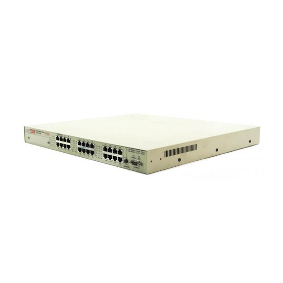
1. PRODUCT OVERVIEW Description This installation and user guide describes the Cabletron Systems ELS100-24TXM Ethernet switch. The switch is IEEE 802.1D-compliant and supports 24 IEEE 802.3u 100Base-TX Fast Ethernet ports. Each port can alternatively operate as an IEEE 802.3i 10Base-T port. In addition, two of the switch’s ports support Fast Ethernet over fiber (IEEE 802.3u... -
Page 16: Features
100Base-FX connections - 1 modular slot for 2 100Base-FX ports using SC connectors • Architecture: - 8-port 10/100 switch ASIC in a distributed switching architecture - 4.2 Gbps internal switching fabric - 12 MB packet buffering (512 KB/port) - 4096 MAC address forwarding table per port; up to 12,288 addresses per system - IEEE 802.3u auto-negotiation for full/half duplex and 10/100... -
Page 17: Front Panel
Test LED Console port * There are 24 total ports on the ELS100-24TXM switch. When the fiber module is installed, these ports become ports 1 and 2, used for fiber connections. Ports 1 and 2 RJ-45 connectors then become disabled. - Page 18 Figure 1-2 shows the Link and Activity LEDs for the 2 100Base-FX ports (fiber port LED functions are defined in Table 1-2). The LEDs are positioned to the left of their associated port. Figure 1-2. 100Base-FX Port LEDs Figure 1-3 shows the Link and Activity port LEDs for 24 10Base-T/ 100Base-TX ports (default configuration).
- Page 19 The port LEDs are grouped to the left of their corresponding RJ-45 ports. Table 1-2 defines the performance of the port LEDs for the 10Base-T/ 100Base-TX ports in both the default configuration and with the LED mode button pressed. Table 1-2. Port LEDs Defined Name Function Fiber Ports...
-
Page 20: Rear Panel
An aggregate address table containing 4096 entries per 8 switch ports is provided for learning, filtering, and forwarding. The switch can support up to a maximum of 12,288 addresses. Addresses are automatically learned by the switch, and can be individually assigned specific forwarding treatment by the network administrator if desired. -
Page 21: Spanning Tree Protocol
LAN segments for purposes of fault tolerance. Two or more physical paths between different segments can be created through the switch, with the Spanning Tree Protocol choosing a single path at any given time and disabling all others. If the chosen path fails for any reason, a disabled alternative is activated, thereby maintaining the connection. -
Page 22: Configuration And Management Interfaces
Configuration and Management Interfaces The ELS100-24TXM switch can be managed using any of the following three methods: • Serial console, out-of-band An RS-232 connection, using a DB-9 connector, is supported for out- of-band switch management. Serial console management is per- formed using a terminal, or computer system running communica- tions software. -
Page 23: Port Mirroring
Broadcast, multicast, and unknown destination address unicast packets received by the switch are typically flooded to all ports on the switch or on a given VLAN. When the number of these types of packets being forwarded is large, the performance of the switch in forwarding packets of other types may suffer. -
Page 24: Bootp/Dhcp
SNMP. LEDs The switch port LEDs provide a quick and accurate display of the integrity of switch connections and port mode. The default operation of the RJ-45 LEDs indicates Link (L) and Activity (A) for each of the ports. The operation of these LEDs can be changed by use of the LED mode button on the switch front panel. -
Page 25: Class Of Service
The ELS100-24TXM switch is ideal for meeting the needs of today’s high performance networks. The switch’s low cost and high port count makes it attractive and affordable for dedicated 10/100Mbps connections to the desktop. -
Page 26: Client/Server Network Application
10Mbps and 100Mbps speeds, through 10Mbps switches with 100Mbps uplinks, or through direct connections. The fiber uplinks are available to connect the switch to a remote location, such as another building floor or a separate building. -
Page 27: Local Backbone Application
100 Mbps ports. Routers and other networking devices can connect off of the switched backbone as well. The fiber uplinks are available to connect the switch to a remote location, such as another building floor or a separate building. -
Page 29: Installation
• Power cord • This document Site Requirements Before you install the switch, make sure the site meets the following requirements: • Mounting Provide a flat table, wall or shelf surface, or an optional 19 in. (48.3 cm) equipment rack. -
Page 30: Mounting The Switch On A Table Or Shelf
Mounting the Switch on a Table or Shelf Mount the switch on a table or shelf in a position which allows access to the front panel RJ-45 ports, visibility of the port LEDs, and access to the power cord. Make sure that the mounting surface can safely support the switch and that there is adequate space around the switch for ventilation and cooling. -
Page 31: Mounting The Switch On A Wall
Figure 2-1 shows the orientation of the mounting ears for attaching the ears to the switch for a wall mount application. Be sure that the wall surface can safely support the switch. Do the following: Mount one of the ears to the switch using two (2) of the supplied screws. -
Page 32: Mounting The Switch In A Rack
Figure 2-2 shows the orientation of the mounting ears for attaching the ears to the switch for a rack mount application. Mount the switch with the front panel facing forward. Do the following: Mount one of the ears to the switch using two (2) of the supplied screws. -
Page 33: Installing A Fiber Uplink Module Into The Switch
Installing a Fiber Uplink Module into the Switch The fiber uplink module option permits you to enable 100Base-FX fiber connections to the switch. A 2 port fiber module can be installed into the modular slot on the left side of the switch (Figure 2-3). -
Page 34: Connecting A Terminal To The Console Port
Terminal Equipment (DTE) connection. Alternatively, this port can be connected to an external modem to enable remote dial-in management. If you connect a terminal to the console port prior to powering the switch, you can observe the progress and results of the power-up diagnostics as the switch goes through its initialization process. -
Page 35: Powering The Switch
If you want to display the results of the tests after the switch has already been turned on, turn the power switch off and then back on. -
Page 36: Els100-24Txm
Memory tests on the CPU RAM are performed after the serial port test. No results are displayed on the console. After these two tests are performed, the operational software of the switch is loaded. A series of more extensive diagnostic tests are then conducted during which the Test LED remains lit. -
Page 37: 10Base-T/100Base-Tx Ports
10Base-T, Section 14 of the IEEE 802.3 specification. The ports are wired with the MDI-X function implemented. Workstations or servers can be connected to the ELS100-24TXM switch using standard straight-through wired cables. For connections to hubs or other switches, a crossover cable may be necessary (refer to the “MDI/MDI-X Crossover Cable Wiring”... -
Page 38: 100Base-Fx Fiber Ports
100Base-FX Fiber Ports The 100Base-FX Fiber ports use SC connectors. Figure 2-7 shows an SC fiber connector being inserted into a fiber port on the ELS100-24TXM. Figure 2-7. Inserting an SC Fiber Connector into a Fiber Port Depending on the fiber uplink module employed (see Table 2-3), these ports support either multi-mode 62.5/125 m fiber or single-mode 9/ 125 m fiber. -
Page 39: Els100-24Txm User Interface
Overview When you have connected a terminal to the console port, or used Telnet to access the switch over the network, access is gained to the console menus. These menus allow you to reconfigure the switch from its factory default settings, as well as to monitor switch status and performance. The menus have a layout similar to the sample Main Menu shown in Figure 3- 1. -
Page 40: User Access
READ/WRITE. READ-ONLY access allows you to view switch information, but not modify any operating parameters. READ/WRITE access allows you to both read and modify switch information. You are required to login with a password before obtaining READ/WRITE access. If no password is entered (press only the [Enter] key), you are logged in with READ-ONLY access. -
Page 41: Factory Defaults
Factory Defaults Table 3-1 lists the factory default settings for the switch configuration parameters. Each of these parameters can be changed via the console menus or Telnet. Table 3-1. Factory Default Settings Parameter Active Aging Time Auto-negotiation Enable Broadcast Cutoff Rate... -
Page 42: Menu Hierarchy
Menu Hierarchy Figure 3-2 shows the ELS100-24TXM switch user interface menu hierarchy. SNMP Configuration Menu System System Name Configuration System Location Menu System Contact IP Address Subnet Mask Default Gateway BootP/DHCP Enable Screen Timeout (minutes) Password Terminal Baud Rate Switch... -
Page 43: Main Menu
Logs out of the console interface. Once you logout, you must enter a password before you can access the console inter- face again. Reset Performs a software reset of the switch by restarting the sys- tem software and reloading all operating parameters. 9032785 Access Control: READ/WRITE... -
Page 44: System Configuration Menu
System Configuration Menu The System Configuration Menu enables modification of system-level switch configuration parameters. Select a from the Main Menu to view the System Configuration Menu. Figure 3-4 shows the System Configuration Menu and the accompanying table describes the System Configuration Menu. -
Page 45: Snmp Configuration Menu
SNMP Configuration Menu The SNMP Configuration Menu allows you to modify SNMP-related configuration parameters. Select a from the System Configuration Menu to view the SNMP Configuration Menu. Figure 3-5 shows the SNMP Configuration Menu and accompanying table describes the SNMP Configuration Menu. -
Page 46: Switch Configuration Menu
Switch Configuration Menu The Switch Configuration Menu allows you to modify switching-related configuration parameters. Select b from the Main Menu to view the Switch Configuration Menu. Figure 3-6 shows the Switch Configuration Menu and the accompanying table describes the Switch Configuration Menu. -
Page 47: Forwarding Table Configuration Menu
The MAC address of each forwarding table entry is displayed along with its type, disposition, and associated port number. Select a from the Switch Configuration Menu to view the Forwarding Table Configuration Menu. Figure 3-7 shows the Forwarding Table Configuration Menu and the accompanying table describes the Forwarding Table Configuration Menu. - Page 48 Selection Description Display Table Redisplays the forwarding table. Make Entry Static Makes a dynamic entry in the forwarding table static. Add Static Entry Adds a static entry to the forwarding table. Delete Static Entry Deletes a static entry from the forwarding table. Modify Static Entry Modifies a static entry from the forwarding table.
-
Page 49: Spanning Tree Configuration Menu
Spanning Tree Configuration Menu The Spanning Tree Configuration Menu allows you to view and modify Spanning Tree parameters. Select b from the Switch Configuration Menu to view the Spanning Tree Configuration Menu. A letter identifies selections that can be modified. All other fields are read-only. Figure 3-8 shows the Spanning Tree Configuration Menu and the accompanying table describes the Spanning Tree Configuration Menu. - Page 50 Bridge Priority 36 ELS100-24TXM User Interface Description Allows you to enable (Yes) or disable (No) the global Spanning Tree operation on the switch. Provides access to the Spanning Tree Port Configura- tion Menu. The time interval between the sending of Configuration BPDUs by the bridge, if it is root (1-10 second range).
-
Page 51: Spanning Tree Port Configuration Menu
Figure 3-9. Spanning Tree Port Configuration Menu Field Description Port ID A unique identifier for a port on the bridge (switch). Port Name The administrative name assigned to the port. Path Cost The contribution of the path through this port, when it is the root port, to the total path cost from this bridge to the root bridge. -
Page 52: Spanning Tree Port #N Configuration Menu
Spanning Tree Port #n Configuration Menu The Spanning Tree Port #n Configuration Menu allows you to view Spanning Tree Port Configuration information for an individual port. Select a from the Spanning Tree Port Configuration Menu to view the Spanning Tree Port # n Configuration Menu. Figure 3-10 shows the Spanning Tree Port # n Configuration Menu and the accompanying table describes the Spanning Tree Port # n Configuration Menu. -
Page 53: Vlan Configuration Menu
VLAN Configuration Menu The VLAN Configuration Menu allows you to configure the operation of Virtual LANs (VLANs) in the switch. Select c from the Switch Configuration Menu to view the VLAN Configuration Menu. Figure 3-11 shows the VLAN Configuration Menu and the accompanying table describes the VLAN Configuration Menu. -
Page 54: Vlan Menu
VLAN Menu The VLAN Menu displays the configuration of VLANs in the switch and allows access to the VLAN #n Configuration Menu to create and configure VLANs. Select b from the VLAN Configuration Menu to view the VLAN Menu. Figure 3-12 shows the VLAN Menu and the accompanying table describes the VLAN Menu. -
Page 55: Vlan #N Configuration Menu
VLAN #n Configuration Menu The VLAN #n Configuration Menu allows you to configure a name for a specific VLAN, add or remove a port in the VLAN, and add or remove an egress port in the VLAN. Select c from the VLAN Menu to view the VLAN #n Configuration Menu. -
Page 56: Vlan Port Menu
VLAN Port Menu The VLAN Port Menu displays a table of VLAN configuration information on a per port basis and allows you to modify the VLAN Port Type. Select c from the VLAN Configuration Menu to view the VLAN Port Menu. Figure 3-14 shows the VLAN Port Menu and the accompanying table describes the VLAN Port Menu. -
Page 57: Class Of Service Configuration Menu
The Class of Service Configuration Menu allows you to configure Class of Service settings for the system as well as to set the Class of Service for VLAN tagged frames. Select d from the Switch Configuration Menu to view the Class of Service Configuration Menu. Figure 3-15 shows the Class of Service Configuration Menu and the accompanying table describes the Class of Service Configuration Menu. -
Page 58: Port Priority Menu
Port Priority Menu The Port Priority Menu allows you to modify and display a table which shows Class of Service configuration information on a per port basis. Select c from the Class of Service Configuration Menu to view the Port Priority Configuration Menu. -
Page 59: Port Menu
Port Menu The Port Menu allows you to display information for each port in a table format, as well as to access the Port Configuration Menu. You can also refresh the screen information. Select c from the Main Menu to view the Port Menu. -
Page 60: Port Configuration Menu
Port Configuration Menu The Port Configuration Menu allows you to configure port settings for a specific port. Select c from the Port Menu to view the Port Configuration Menu. Figure 3-18 shows the Port Configuration Menu and the accompanying table describes the Port Configuration Menu. PORTS 1-5 CONFIGURATION a Port Name b. -
Page 61: Switch Statistics Screen
Switch Statistics Screen The Switch Statistics Screen provides a summary display of port-level statistics, and provides access to the Port Statistics screens. You can also clear or refresh the statistics. Select d from the Main Menu to view the Switch Statistics Screen. Figure 3-19 shows the Switch Statistics Screen and the accompanying table describes the Switch Statistics Screen. -
Page 62: Switch Summary Screen
Switch Summary Screen The Switch Summary Screen allows you to display sum total statistics for all ports of the switch. You can also clear or refresh the statistics. Select s from the Switch Statistics Screen to view the Switch Summary screen. -
Page 63: Port Statistics Screen
Port Statistics Screen The Port Statistics Screen allows you to display statistics for each port on the switch. Many of these statistics correspond to the Statistics group of RMON. You can also refresh or clear the statistics. Select s from the Switch Statistics Screen to view the Port Statistics screen. - Page 64 Field Description Multicasts Transmitted Total number of multicast frames transmitted on the port. Multicasts Received Total number of multicast frames received on the port. Bytes Transmitted Total number of bytes transmitted on the port. Bytes Received Total number of bytes received on the port. Pause Frames Transmitted Total number of flow control pause frames transmitted on the port.
-
Page 65: General Information Screen
The version of system software currently operating on the switch. The serial number of the switch. The base MAC address of the switch (port 1 ad- dress). The number of minutes the switch has been oper- ational since the last power cycle or reset. -
Page 66: Download Software Menu
Download Software Menu The Download Software Menu allows you to set up and initiate a software download. Select f from the Main Menu to view the Download Software Menu. Figure 3-23 shows the Download Software Menu and the accompanying table describes the Download Software Menu. DOWNLOAD SOFTWARE a. -
Page 67: Save Current Configuration
Save Current Configuration The Save Current Configuration screen ensures that all changes made to the ELS100-24TXM switch via the console menus will be stored in the event of power outages or power cycles. To save your current configuration, do the following: Select g from the Main Menu to view the Save Current Configuration screen. -
Page 68: Reset
Reset The Reset screen allows you to perform a switch hardware reset. You are first prompted as to whether or not to save the current switch configuration. To reset the switch, do the following: Select j from the Main Menu to view the Reset screen. -
Page 69: Configuring & Monitoring The Switch
Setting password protection for the switch to prevent unauthorized access to console menus • Assigning an IP address for the switch if you plan to manage the switch using SNMP, or if you use Telnet to access the switch •... -
Page 70: Setting Password Protection
Main Menu, all access rights change to READ-ONLY. The current level of access control is indicated at the top of the management screen. If you forget your password, contact your Cabletron Systems Support Representative. You are automatically logged out from the console menus based on the Screen Timeout setting in the System Config- uration Menu. -
Page 71: Assigning An Ip Address
Assigning an IP Address To assign an IP address to the switch, do the following: Select System Configuration Menu from the Main menu. Select IP address from the menu and enter the IP address. Press [Enter]. The IP address is now programmed. The subnet mask is automatically set to correspond to the class of the address entered. -
Page 72: Setting Snmp Management Access
Viewing Switch Statistics To view switch statistics, do the following: Select Switch Statistics Screen from the Main Menu. The screen lists the main statistical counts for all ports on the switch simultaneously. Select Switch Summary from the Switch Statistics Screen. -
Page 73: Configuring Port Mirroring
To configure port mirroring, do the following: Select Switch Configuration Menu from the Main Menu. Turn the switch port mirroring operation on or off by toggling the Port Mirroring Enable option (pressing g). Select Mirrored Port for the port to be mirrored (traffic information source) and enter the number of the port. -
Page 74: Downloading Via The Serial Port
A serial download is the easiest method to upgrade the ELS100-24TXM switch software, requiring the least amount of equipment and configuration. To download switch software via the serial port, do the following: Select Download Software Menu from the Main Menu. Select Start XMODEM Download. -
Page 75: Configuring Spanning Tree Parameters
If necessary, configure the address of an IP gateway to reach the server from the switch using the Default Gateway field on the System Configuration Menu. Configure the TFTP server by copying the download file from the upgrade disk to an appropriate directory and starting the server. -
Page 76: Configuring Vlans
To configure VLANs, do the following: Select Switch Configuration Menu from the Main Menu. Select VLAN Configuration Menu. Turn the global switch VLAN operation on or off by toggling the VLAN Enable option by pressing a. Select VLAN Menu. The VLAN Menu displays. This menu displays the current configura- tion of VLANs in the system. -
Page 77: Configuring Port Operation
Select Class of Service Configuration Menu from the Switch Configuration Menu. Turn the global switch Class of Service operation on or off by toggling the Class of Service Enable option by pressing a. Select Priority Threshold and type a number between 0 and 7. -
Page 78: Configuring The Forwarding Table
MAC addresses, allowing you to maintain the efficiency and security of your network. You can search for specific MAC addresses by the address itself or by port number. The switch learns addresses dynamically from incoming packets and builds a table of these addresses along with their associated ports. -
Page 79: Configuring Broadcast Cutoff Rate
Select Broadcast Cutoff Rate, enter the rate value, and press [Enter]. Valid values are in the range from 100 to 500,000 per second. This rate value is applied to each grouping of 8 ports on the switch. A set- ting of 500,000 essentially disables this feature. -
Page 80: Setting A Default Gateway
When this option is enabled, the switch first tries to obtain an IP address from a DHCP server. If this fails, the switch tries to obtain an IP address from a BootP server. If this fails, the switch uses a previously configured IP address, if one exists. -
Page 81: Snmp Management
Managed entities supporting SNMP typically contain software, which runs locally on the device and is referred to as an agent. In Figure 5-1, software in an ELS100-24TXM switch functions as an agent, monitoring and controlling the functionality of the switch. -
Page 82: Mib Objects
RFC 1493 - Definitions of Managed Objects for Bridges • RFC 1757 - Remote Network Monitoring Management Information Base The ELS100-24TXM switch also supports Cabletron Systems proprietary MIB extensions. RFC 1213 (MIB-II) RFC 1213 provides management of switch system-level parameters, including TCP/IP protocol-related statistics, IP addressing, routing table information, and interface statistics for each switch port. -
Page 83: Rfc 1398 (Ethernet Mib)
RFC 1398 (Ethernet MIB) RFC 1398 provides management and monitoring for the Ethernet-specific aspects of each port on the switch. This is the Ethernet-specific statistics subgroup of the MIB-II Transmission group. This group provides a set of statistics related to Ethernet’s physical level operation. Specifically, error and collision-related statistics are presented. -
Page 84: Cabletron Systems Proprietary Mib Extensions
Cabletron Systems Proprietary MIB Extensions Areas of ELS100-24TXM switch functionality not covered by the standard RFC MIBs are specified in the Cabletron Systems private MIB. This MIB definition is specified separately from MIB-II. Areas covered in this MIB include various system, switch, and port level information. System information MIB variables are shown in Table 5-1, switch information variables in Table 5-2, and port variables in Table 5-3. - Page 85 TFTP server IP address for TFTP downloads. TftpFilename Filename of the download upgrade file on the TFTP server. PowerUpCount Cumulative number of times switch has powered up or been reset. BroadcastCutoffRate Per second rate past which broadcast and destination un- known unicast frames are not flooded on each group of 8 ports on the switch.
- Page 86 The type of VLAN this port is operating as, either hybrid or access. SwitchPriorityEnable Enable/disable global traffic priority in the switch. SwitchPriorityThreshold Priority threshold level (0-7) in the switch which defines switch traffic to be high or low priority. SwitchPriorityPortTable Priority table indexed by SwitchPriorityPortId. SwitchPriorityPortId Port number or ID.
-
Page 87: Compiling Mib Extensions: Cabletron Website
SNMP management platform. Application modules specific to managing the ELS100-24TXM switch under different network management platforms are available. Contact Cabletron Systems for information regarding supported platforms. If you require assistance, contact the Cabletron Systems Global Support Center directly at either:... -
Page 89: Appendix A. Technical Specifications
APPENDIX A. TECHNICAL SPECIFICATIONS General Standards Compliance IEEE 802.1D Transparent Bridging Specifications (ISO/IEC 10038) IEEE 802.1p Traffic Class Expediting and Dynamic Multicast Filtering IEEE 802.1Q Virtual Bridged Local Area Networks IEEE 802.2 Local Area Networks, Logical Link Control (LLC) IEEE 802.3 CSMA/CD 9 (ISO/IEC 8802-3) IEEE 802.3i 10Base-T (ISO/IEC 8802-3, clause 14) IEEE 802.3u 100Base-TX (ISO/IEC 8802-3, clause 25) IEEE 802.3u 100Base-FX... -
Page 90: Electrical Specifications
Electrical Specifications Input voltage: Input frequency: Maximum power consumption: Physical Height: Length: Width: Weight: Microprocessor Type: Speed: Memory Processor DRAM: Packet Buffer Memory: Flash Memory: 76 Technical Specifications 100-240 VAC 50-60 Hz 75 VA 1.75 in. (4.4 cm) 16.0 in. (40.6 cm) 17.1 in. -
Page 91: Port Specifications
Table A-1 shows the console port pin assignments. Table A-1. RS-232 Console Port Pin Assignments 10Base-T and 100Base-TX Ports The ELS100-24TXM switch provides IEEE 802.3u auto-negotiation on its 10Base-T/100Base-TX ports for 10/100 speed and full/half duplex operation. Table A-2 shows the 10Base-T/100Base-TX pinouts. These ports are wired MDI-X. -
Page 92: Mdi/Mdi-X Crossover Cable Wiring
Power cord sets for use in other countries must meet the requirements of the country where you use the switch. For more information on power cord set requirements, contact your Cabletron Systems Support Representative. General Requirements The requirements listed below are applicable to all countries: •... -
Page 93: Country-Specific Requirements
Country-Specific Requirements Table A-3 lists the power cord set requirements by country and identifies the accredited agency within that country. Table A-3. Power Cord Set Requirements by Country Country Australia Austria Belgium Canada Denmark Finland France Germany Italy Japan Netherlands Norway Sweden Switzerland... -
Page 95: Appendix B. Spanning Tree Concepts
Spanning Tree Features The ELS100-24TXM switch meets the requirements of the Spanning Tree Protocol (STP) by performing the following functions: •... -
Page 96: Spanning Tree Protocol In A Network
If the connection between A and B goes down, the link between A and C becomes active, thereby establishing a path between A and B through switch C. Additionally, if the connection between B and C goes down, the link between A and C becomes active, establishing a path between B and C through switch A. -
Page 97: Spanning Tree Protocol Parameters
Several configuration parameters control the operation of the Spanning Tree Protocol. Table B-1 describes the parameters and lists the ELS100-24TXM switch default settings for each parameter. You can cause serious network performance degradation if you do not fully understand Spanning Tree concepts. -
Page 98: Spanning Tree Protocol Operation
Spanning Tree Protocol Operation When the Spanning Tree Protocol is enabled for the first time or when there is a change in the network topology, such as a failure or the addition or removal of a component, the Spanning Tree Protocol automatically sets up the active topology of the current network. - Page 99 There are five (5) states that the ports can be in for spanning tree: • Blocking: A port in this state does not participate in the transmission of frames, thus preventing duplication arising through multiple paths existing in the active topology of the bridged LAN. •...
-
Page 101: Appendix C. Flow Control
Figure C-1. Flow Control for Full and Half Duplex Applications Each port of the switch has a transmit queue which buffers frames to be sent out on that port. In this example, large amounts of data are being sent from Workstation A (connected to port X) and other ports on the switch to Workstation B (connected to port Y).The queue on port Y starts... - Page 102 For the full duplex pause frame mechanism to work, the device connected to the switch port must also support IEEE 802.3x flow control. Flow Control is configurable per port in the Port Configuration Menu of the console menu or via SNMP.
-
Page 103: Appendix D. Virtual Lans (Vlans)
In the example in Figure D-1 below, the workstations attached to the top switch are members of the same two VLANs as the workstations attached to the bottom switch. The 802.1Q tags are used to carry VLAN information in the frames traveling between the two switches. -
Page 104: Els100-24Txm Vlan Configuration
VLAN operation on the ELS100-24TXM is disabled by default. When VLANs are enabled, all frames are transferred internally through the switch with a VLAN tag. This tag may already be on the frame entering the switch, or added to the frame by the switch. VLAN information already existing on frames entering the switch is automatically handled by the switch. -
Page 105: Vlan Egress Ports
VLAN tagged frames are not allowed to enter or exit an Access port. If a tagged frame enters the switch on an Access port, the switch will drop the frame. End-user stations which do not support 802.1Q tags should be attached to ports on the switch configured as Access ports. -
Page 106: Vlan Hybrid Ports
VLAN Hybrid Ports A VLAN Hybrid port is used to connect one or more VLAN-aware or VLAN-unaware devices to the switch. Both tagged and untagged frames can be received and transmitted on Hybrid ports. Egress ports should typically be configured as Hybrid ports. - Page 107 In Example 3 in Figure D-3B, an untagged frame arrives at the left port (1). The switch tags the frame with the PVID for VLAN X (2). Since the destination MAC address has already been learned as a tagged station on VLAN X on the outgoing port, the frame is sent out with a VLAN X tag.
-
Page 108: Vlan Application Example
A network administrator can use VLANs to define user groups regardless of the physical LAN segment to which they are connected. The use of Hybrid and Access links can further refine traffic flow in a multi-switch environment. Figure D-4 shows the combination of both Hybrid and Access links used in a network with three different VLANs. -
Page 109: Appendix E. Class Of Service
• normal As traffic enters the switch, it is assigned to one of the two priority levels according to information located in the 802.1Q header tag of the frame (see Appendix D, “Virtual LANs”) or according to the incoming port number. - Page 110 Figure E-1 shows priority queuing operating within a switch. Frames entering the switch through ports 1 and 4 are tagged as normal traffic and placed in a normal priority queue on the outbound port. Frames entering through ports 2 and 5 are tagged as high priority traffic and placed in a high priority queue on the outbound port.
-
Page 111: Appendix F. Acronyms & Abbreviations
APPENDIX F. ACRONYMS & ABBREVIATIONS Term Definition 10Base-T 10Mbps twisted-pair Ethernet 100Base-FX 100Mbps fiber Fast Ethernet 100Base-TX 100Mbps twisted-pair Fast Ethernet ANSI American National Standards Institute ASIC Application Specific Integrated Circuit BootP Bootstrap Protocol BPDU Bridge Protocol Data Unit CAT5 Category 5 Class of Service Cyclic Redundancy Check... - Page 112 Term Definition Receive Data SNMP Simple Network Management Protocol Spanning Tree Protocol TCP/IP Transmission Control Protocol/Internet Protocol TFTP Trivial File Transfer Protocol Transmit Data Unshielded Twisted Pair VLAN Virtual Local Area Network Wide Area Network 98 Acronyms & Abbreviations ELS100-24TXM...
-
Page 113: Index
Class of Service Configuration Menu, 43 client/server network application, 12 communication settings, 21 community names, 31, 58 Configuring Port Mirroring, 59 configuring the switch common tasks, 55 connecting network cables, 22 console port, 3, 20, 77 connecting to, 20 defined, 3... - Page 114 Microprocessor, 76 mirrored port, 32 mirroring port, 32 modes of access read-only and read/write, 26 mounting ears, 17, 18 Mounting the Switch, 16, 17 rack, 18 table or shelf, 16 wall, 17 network configuration status, 57 password protection, 8, 26, 56...
- Page 115 Spanning Tree Protocol defaults, 83 Standards Compliance IEEE, 75 store-and-forward, 7, 83, 98 subnet mask, 57 Switch Configuration Menu, 29, 32 switch statistics, 58 Switch Statistics Screen, 29, 47 Switch Summary Screen, 48 System Configuration Menu, 29, 30 Telnet, 25...
- Page 116 102 Index ELS100-24TXM...
- Page 117 DOCUMENT 591-0046-02A...
Need help?
Do you have a question about the SmartSTACK ELS100-24TXM and is the answer not in the manual?
Questions and answers