Cabletron Systems Cabletron CyberSWITCH CSX400 User Manual
Cabletron systems switch user's guide
Hide thumbs
Also See for Cabletron CyberSWITCH CSX400:
- User manual (194 pages) ,
- Installation manual (118 pages) ,
- Configuration manual (164 pages)
Table of Contents
Advertisement
Quick Links
Advertisement
Table of Contents
Troubleshooting

Related Manuals for Cabletron Systems Cabletron CyberSWITCH CSX400


Summary of Contents for Cabletron Systems Cabletron CyberSWITCH CSX400
- Page 1 CSX400 AND CSX400-DC USER’S GUIDE...
-
Page 3: Fcc Notice
Notice Cabletron Systems reserves the right to make changes in specifications and other information contained in this document without prior notice. The reader should in all cases consult Cabletron Systems to determine whether any such changes have been made. The hardware, firmware, or software described in this manual is subject to change without notice. -
Page 4: Vcci Notice
IMPORTANT: Before utilizing this product, carefully read this License Agreement. This document is an agreement between you, the end user, and Cabletron Systems, Inc. (“Cabletron”) that sets forth your rights and obligations with respect to the Cabletron software program (the “Program”) contained in this package. The Program may be contained in firmware, chips or other media. -
Page 5: United States Government Restricted Rights
Acquisition Regulations, Section 52.227-7013 (c) (1) (ii) and its successors, and use, duplication, disclosure by the Government is subject to restrictions as set forth in subparagraph (c) (1) (ii) of the Rights in Technical Data and Computer Software clause at 252.227-7013. Cabletron Systems, Inc., 35 Industrial Way, Rochester, New Hampshire 03867-0505. CSX400 and CSX400-DC User’s Guide... - Page 6 Rochester, NH, USA ___________________________________ Location CSX400 and CSX400-DC User’s Guide DECLARATION OF CONFORMITY 89/336/EEC 73/23/EEC 91/263/EEC Cabletron Systems, Inc. 35 Industrial Way PO Box 5005 Rochester, NH 03867 Mr. J. Solari Cabletron Systems Limited Nexus House, Newbury Business Park London Road, Newbury...
-
Page 7: Table Of Contents
CHAPTER 1 INTRODUCTION Related Documentation ... 1 How to Use This Guide ... 1 Document Conventions... 3 Getting Help ... 4 CHAPTER 2 ABOUT THE CSX400 CSX400 Hardware ... 5 WAN Connection ... 5 Ethernet LAN Connection... 7 Remote Management Capabilities ... 7 Optional Features ... - Page 8 Contents CHAPTER 3 ISDN LINE ORDERING AND CONFIGURATION Arranging ISDN Service ... 23 Telephone Switch Support ... 24 ISDN BRI Line Configuration ... 24 ISDN BRI Configurations ... 25 SPIDs, Directory Numbers and Telephone Numbers ... 25 Telephone Switch Parameters ... 26 CHAPTER 4 PLANNING FOR CSX400 ISDN CONFIGURATION Configuration Process and Terminology ...
- Page 9 CSX-COMP/ENCR Installation ... 62 Installing the CSX400... 63 Tabletop and Shelf Installations ... 63 CSX400 and CSX400-DC Rackmount Installation ... 64 Connecting the CSX400 to the Power Source ... 68 Connecting the CSX400-DC to the Power Source... 69 CHAPTER 7 CSX400 CONFIGURATION WITH Ethernet Configuration ...
- Page 10 Contents CHAPTER 8 GENERAL CONFIGURATION USING LOCAL MANAGEMENT Chapter Organization ... 125 Local Management Overview... 126 Management Agent ... 126 Local vs. Remote Management ... 126 Local Management Screen Elements... 127 Local Management Keyboard Conventions... 129 Navigating Within Local Management Screens ... 130 Establishing a TELNET Connection ...
- Page 11 Bridge Setup Screen ... 149 Bridge Setup Screen Fields ... 149 Selecting a Spanning Tree Protocol ... 150 Selecting the Bridge Port Administrative Status ... 150 Selecting the Bridge Port Pair Administrative Status... 151 Router Setup Screen... 152 Router Setup Fields ... 152 IP Configuration Screen ...
- Page 12 Contents CHAPTER 10 TROUBLESHOOTING Troubleshooting CSX400 Hardware ... 208 Power (PWR) LED is OFF ... 208 Processor (CPU) LED is OFF... 208 Processor (CPU) LED is RED ... 208 Troubleshooting the LAN ... 208 Collision (CLN) LED is RED ... 208 Link (LNK) LED is OFF ...
- Page 13 APPENDIX B WPIM CABLE SPECIFICATIONS WPIM-T1 ... 223 WPIM-SY ... 225 EIA-449... 226 V.35 ... 227 EIA-232... 229 X.21 ... 230 EIA-530, EIA-530 ALT A, EIA-530 A, and EIA-530 A ALT A... 231 WPIM-DDS... 233 WPIM-E1... 234 WPIM-DI... 236 WPIM-HDSL... 237 WPIM-S/T...
- Page 14 Contents xii CSX400 and CSX400-DC User’s Guide...
-
Page 15: Chapter 1 Introduction
Use the READ ME FIRST! document included with the CSX400 to set up your computer before starting configuration. Use the Cabletron Systems QuickSTART Guide (the CD insert of the QuickSET CD case) to install the CSX400. Use the appropriate Cabletron Systems WPIM Local Management Guide to connect your CSX400 to a WAN using a TELNET connection. - Page 16 6, Installation, provides detailed installation instructions for attaching the CSX400 and CSX400-DC to a network. Chapter CSX400 Configuration with CSX400 to a Wide Area Network (WAN) using Cabletron Systems QuickSET management utility. Chapter General Configuration Using Local configuring the CSX400 through a TELNET connection.
-
Page 17: Document Conventions
Document Conventions The following conventions are used throughout this guide: Note symbol. Calls the reader’s attention to any item of information that may be of NOTE special importance. Tip symbol. Conveys helpful hints concerning procedures or actions. Caution symbol. Contains information essential to avoid damage to the equipment. CAUTION Electrical Hazard Warning symbol. -
Page 18: Getting Help
A description of any action(s) already taken to resolve the problem (e.g., changing mode switches, rebooting the unit, etc.) • The serial and revision numbers of all involved Cabletron Systems products in the network • A description of your network environment (layout, cable type, etc.) •... -
Page 19: About The Csx400
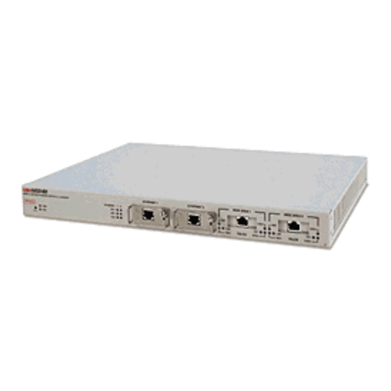
About the CSX400 The CSX400 (Figure 1) is an access device that provides Ethernet Local Area Network (LAN) connectivity via two Ethernet Port Interface Modules (EPIMs), and offers high-speed Wide Area Network (WAN) access to remote sites via two WAN Port Interface Modules (WPIMs). The CSX400 supports IEEE 802.1d transparent bridging, IP and IPX routing, ISDN, Dynamic Host Configuration Protocol (DHCP), Network Address Translation (NAT) routing, and Inverse Multiplexing (IMUX) between Ethernet LANs across a WAN. - Page 20 About the CSX400 • The WPIM-Sync provides a synchronous serial connection of up to 2.048 Mbps to external communications equipment (e.g., a multiplexer or CSU/DSU). The WPIM-Sync uses a subminiature 26-pin connector that supports the electrical signal interfaces listed below. Appendix B, provides complete part number and cable pinout information for the following electrical signal interfaces:...
-
Page 21: Ethernet Lan Connection
FLASH EEPROMs — Read-Only Memory (EEPROM) that allows new and updated firmware to be downloaded in conjunction with Cabletron Systems QuickSET or any device using BootP or TFTP protocols. Cabletron Systems LANVIEW Status Monitoring and Diagnostics System is LANVIEW LEDs —... -
Page 22: Optional Features
About the CSX400 Optional Features The CSX400 can be installed in a 19-inch rack with the Rack Mounting Capabilities — included mounting brackets and screws. Refer to Chapter 6 Installation, for complete rack mounting instructions. The same industry standard Hardware Data Compression Module (CSX-COMP/ENCR) — STAC Electronics Stacker LZS Compression algorithm supported by CSX400 software is made available by an optional hardware data compression module that accelerates data compression for the CSX400 over PPP and Frame Relay. -
Page 23: Wan Protocols
WAN Protocols This device supports the following WAN protocols over the WAN port: • Point-to-Point Compression Control Protocol (CCP) as defined by RFC 1962 • Inverse Multiplexing (IMUX) • Dynamic Host Configuration Protocol (DHCP) as defined by RFC 1541 • Network Address Translation (NAT) routing as defined by RFC 1631 •... -
Page 24: Firmware Data Compression
Inverse Multiplexing (IMUX) Cabletron Systems products that support IMUX, such as the CSX400, HSIM-W6 and NOTE HSIM-4T1, must exist on both ends of the WAN link for the IMUX function to work. -
Page 25: Hdlc
HDLC Cabletron Systems has provided the High-level Data Link Control (HDLC) protocol which is used in conjunction with the Inverse Multiplexing (IMUX) feature and the WPIM-HDSL to conserve a user’s WAN bandwidth between two Cabletron Systems products, over a point-to-point connection. -
Page 26: Point-To-Point Protocol (Ppp)
About the CSX400 The NAT method allows several DHCP clients on a sub network to connect to WAN clients by allowing the DHCP clients to share a single public IP address. When the CSX400 uses NAT, the NAT method modifies the IP headers and addresses, and the selected fields in upper layer protocol headers. -
Page 27: Lqm
About the CSX400 In half-duplex operation, the authenticator device challenges the peer device by generating a CHAP challenge, and the challenge contains an MD5 algorithm with a random number that has your encrypted password and system name. The peer device then applies a one-way hash algorithm to the random number and returns this encrypted information along with the system name in the CHAP response. -
Page 28: Isdn
About the CSX400 ISDN ISDN provides an inexpensive switched digital access to remote sites. The ISDN BRI standard provides for two high speed 64 Kbps bearer (B) channels used for voice or data connections and one 16 Kbps signaling data (D) channel used for call setup, signaling and other information. ISDN allows all types of information to be transmitted including voice, data, fax and video. -
Page 29: Isdn Back-Up
About the CSX400 ISDN Back-up The ISDN back-up feature provides a back-up link for a remote site or branch office when one or more primary WAN interfaces for a frame relay circuit or a nailed-up PPP connection fails. The WPIM-S/T serves as the backup medium for this primary connection. The WPIM-S/T uses the ISDN interfaces to back-up any primary interfaces which have been configured for ISDN back-up. -
Page 30: Hdsl
About the CSX400 HDSL High-bit rate Digital Subscriber Line (HDSL) technology uses existing copper twisted pair cables designed for conventional analog voice transmission from a telephone carrier servicing area as a low-cost alternative to the quality and speed of fiber optic cables, and provides high-speed full-duplex digital transmission links of up to 1.544 Mbps. - Page 31 About the CSX400 Routing provides a way to transfer user data from source to destination over different Routing — LAN and WAN links using one or more network protocol formats. Routing relies on routing address tables to determine the best path for each packet. Routing tables can be seeded (i.e., addresses for remote destinations are placed in the table along with network address masks and a metric for path latency).
-
Page 32: Bridging And Routing Protocol Filtering
About the CSX400 Bridging and Routing Protocol Filtering Filtering is used to allow efficient usage of network resources and provide security for your network and hosts. The CSX400 supports IP Internet Firewall filtering to prevent IP Internet Firewall — unauthorized access to your system and network resources from the Internet or a corporate Intranet. -
Page 33: Simple Network Management Protocol (Snmp)
This access level allows editing of some device configuration parameters not read-write — including changing system passwords. This access level allows full management privileges. At this level you must access super-user — the CSX400 to run QuickSET. Simple Network Management Protocol (SNMP) The CSX400 provides SNMP agent support for the following: standard and Enterprise Specific Management Information Bases (MIBs), and support for standard and Enterprise Specific SNMP Traps. - Page 34 About the CSX400 Cabletron Enterprise MIBs Cabletron Enterprise MIBs include the following: CTWAN-MIB, CTMIB2-EXT-MIB, CTDOWNLOAD-MIB, CTBRIDGE-MIB, RREV-4-MIB, CTROUTER-MIB, CTFAULT-MIB, CTIP-MIB, CHASSIS-MIB, CTNETDIAG-MIB, IP-MIB, IPX-MIB, CTDEFAULT-MIB, CTNAT-MIB.TXT, CTDHCP-MIB.TXT, CTWAN-IMUX-MIB, CTISDN-DIALCONTROL-MIB, CTISDN-DCHANNEL-MIB, and CTISDN-REMOTEPROFILE-MIB. SNMP Trap Support SNMP Traps are notifications of network events sent by an SNMP compliant device to an SNMP management station.
- Page 35 • IP Framing Type has been changed on interface # • IP has detected Link UP on interface # • IP has detected Link DOWN on interface # • IP Primary address has been changed on interface # • IP Secondary address has been changed on interface # •...
-
Page 36: Software And Firmware Upgrades
About the CSX400 • IPX has detected Port DOWN (WAN devices only) • IPX RIP has been enabled on interface # • IPX RIP has been disabled on interface # • IPX SAP has been enabled on interface # • IPX SAP has been disabled on interface # Software and Firmware Upgrades Software and Firmware upgrades can be performed remotely through the Windows-based... -
Page 37: Chapter 3 Isdn Line Ordering And Configuration
ISDN Line Ordering and Configuration This chapter provides ISDN BRI (Basic Rate Interface) line ordering and configuration information. It contains the following sections: • Arranging ISDN Service • Telephone Switch Support • ISDN BRI Line Configuration • SPIDs, Directory Numbers and Telephone Numbers •... -
Page 38: Telephone Switch Support
ISDN Line Ordering and Configuration Telephone Switch Support Your telephone company may offer a variety of ISDN switch types. You must contact your service provider and find out which type of ISDN service is available. The following switch types are currently supported by the CSX400 within the U.S.: •... -
Page 39: Isdn Bri Configurations
ISDN Line Ordering and Configuration In the U.S. and Canada, Network Terminator equipment (NT1) is required to provide an interface between the CSX400 and the ISDN line. The NT1 offers conversion between the two-wire twisted pair (U-loop interface) used by telephone companies and the four-wire terminal equipment (S/T Interface) as well as line-testing capabilities. -
Page 40: Telephone Switch Parameters
ISDN Line Ordering and Configuration Service Profile Identifiers SPIDs, also assigned by the ISDN service provider, identify the services and features that the telephone company switch provides to the ISDN device. Commonly implemented in the U.S. and Canada, the SPID is often derived from the directory number, combined in a series with other digits. - Page 41 Table 1 National ISDN 1 (NI-1) (Continued) ISDN Switch Parameters CSD Limit CA Pref EKTS Nail Up Table 2 AT&T 5ESS with Custom Software ISDN Switch Parameters Multipoint Terminal Type Display MTERM MAXB CHL ACT USR CSD CHL CSD Limit CA Pref Nail Up ISDN Line Ordering and Configuration...
- Page 42 ISDN Line Ordering and Configuration ISDN Switch Parameters EKTS Ringing Indicator Release Key PVER MAXKEYS Nail Up 28 CSX400 and CSX400-DC User’s Guide Table 3 DMS-100 Value Circuit Switched Data & Voice Circuit Switched Data & Voice Signaling Only Dynamic None...
-
Page 43: Chapter 4 Planning For Csx400 Isdn Configuration
Planning for CSX400 ISDN Configuration This chapter explains the CSX400 ISDN-BRI configuration process and terminology. It also describes the information that is required for configuration. Configuration Process and Terminology During configuration, you specify information identifying the CSX400 and define the LAN and WAN connections of the CSX400. -
Page 44: Collect Network Information
Planning for CSX400 ISDN Configuration Collect Network Information Before you begin, you need to obtain information about the network to which you are adding the CSX400. Some of the information is obtained from your central site or remote site network administrator. -
Page 45: Isdn Line Information
ISDN Line Information You need to know the telephone switch type and phone numbers associated with the ISDN line. The telephone switch types supported are listed in provider gives you up to three sets of numbers for identifying the ISDN line and attached devices. You may be assigned none, one or two SPIDs or DNs and this varies by service provider and country. -
Page 46: Network Information Diagrams
Planning for CSX400 ISDN Configuration Network Information Diagrams It is helpful to draw a diagram including all locations, addresses, router names, etc. This section includes diagrams needed to configure the CSX400. You may need different addressing information depending on whether you are configuring IP routing and/or NetWare IPX routing. The diagrams show the information required to configure only the CSX400. - Page 47 Planning for CSX400 ISDN Configuration If the CSX400 is to direct traffic to networks or stations beyond the TCP/IP Route Addresses — remote router, the routing table in the CSX400 can be “seeded” with static IP routes. An IP route includes an IP address, subnet mask and metric.
- Page 48 Planning for CSX400 ISDN Configuration If the remote router supports unnumbered mode, neither address needs to be specified. provides a simple example of an unnumbered mode configuration. CSX400 For numbered mode, consider the capabilities of the remote router as well as your requirements. Specify a Source WAN IP address if the CSX400 must be on the same subnetwork as the remote router.
- Page 49 Specify a Remote WAN IP Address if the remote router does not support IP address negotiation under PPP (i.e., does not have a pre-assigned IP address as shown in 128.1.129.1 255.255.255.0 CSX400 *SOURCE IP ADDRESS *SPECIFY SOURCE IP ADDRESS IF IT MUST BE ON SAME SUBNETWORK AS THE REMOTE ROUTER. **SPECIFY REMOTE IP ADDRESS IF REMOTE ROUTER DOES NOT HAVE A PRE-ASSIGNED IP ADDRESS.
- Page 50 Planning for CSX400 ISDN Configuration An Ethernet LAN IPX network number is required for the CSX400 NetWare IPX Routing — local Ethernet LAN connection. The ISDN WAN link to each remote router must have an assigned IPX network number. IPX Routes and IPX SAPs for each remote router are also required for the configuration process.
- Page 51 Planning for CSX400 ISDN Configuration If the CSX400 is to direct traffic to network segments and servers beyond the IPX Routes — remote router, the routing table in the CSX400 can be “seeded” with static IPX routes. An IPX route includes a network number, hop count and ticks. The hop count is the number of routers through which traffic must pass to reach the remote network segment or server.
-
Page 52: Network Information Tables
Planning for CSX400 ISDN Configuration Servers can have internal and external node numbers. The internal node Node Numbers — number is a logical number assigned by the system administrator to the server. The external node number is the MAC address of the server. When adding SAP services to the SAP table, internal node numbers are used. - Page 53 Table 4 Configuring System Settings (Continued) Configuration Section Item ISDN Line Numbers (supplied by the service provider) System Settings ISDN Settings Type of Telco switch System Settings Ethernet IP Address and Ethernet IP Address Subnet Mask System Settings Ethernet IPX Network Ethernet IPX Network # Number Table 5 Configuring the Remote Router Database...
- Page 54 Planning for CSX400 ISDN Configuration Table 5 Configuring the Remote Router Database (Continued) Remote Router Configuration Database TCP/IP Route Addresses IPX Routes IPX SAPs a. Used only in PPP numbered mode of addressing b. Used only in PPP numbered mode of addressing Make one chart for each remote router in the remote router database.
- Page 55 Table 6 Bridging and Routing Controls Bridging/Routing Item Configuration Database Remote Bridging Destination Bridging/Routing TCP/IP Routing NetWare IPX Routing Internet Firewall Planning for CSX400 ISDN Configuration Description Destination dialed when bridging any outbound data traffic (required for outbound bridging) TCP/IP routing to all destinations On or IPX routing to all destination On or Off Internet Firewall active or not CSX400 and CSX400-DC User’s Guide 41...
-
Page 56: Sample Configuration
Planning for CSX400 ISDN Configuration Sample Configuration A sample configuration of a hypothetical network is provided in this section. small office (FP2) accessing a central site (FP3) via an ISDN link. The small office also has access to Internet through an Internet Service Provider (ISP). The small office and central site have IP routing with a Class B addressing scheme and IPX routing. - Page 57 Table 7 CSX400 Sample Configuration Settings Configuration Section System Settings System Settings Dial Authentication Password System Settings ISDN Settings System Settings Ethernet IP Address System Settings Ethernet IPX Network # Planning for CSX400 ISDN Configuration Item Setting Router Name Message Configured_Mar_1996 Dial Authentication FP2passwd...
- Page 58 Planning for CSX400 ISDN Configuration Configuration Section Remote Router Database Dial Settings Remote Router Database Dial-In Security Remote Router Database Bridging Remote Router Database TCP/IP Route Addresses 44 CSX400 and CSX400-DC User’s Guide Table 8 Remote Router: FP3 Item Setting ISDN Phone #1 5551113 ISDN Phone #2...
- Page 59 Configuration Section Remote Router Database NetWare IPX Routes Remote Router Database NetWare IPX SAPs a. Used only in PPP numbered mode of addressing b. Used only in PPP numbered mode of addressing Use one chart for each remote router in the remote router database. NOTE Table 9 Remote Router: ISP (Internet Service Provider) Configuration Section...
- Page 60 Planning for CSX400 ISDN Configuration Table 9 Remote Router: ISP (Internet Service Provider) (Continued) Configuration Section Remote RouterDatabase Bridging Remote Router Database TCP/IP Routes Remote Router Database NetWare IPX Routes Remote Router Database NetWare IPX SAPs a. Used only in PPP numbered mode of addressing b.
-
Page 61: Names And Passwords Example
Configuration Section Bridging and Routing Names and Passwords Example In the sample configuration provided in site FP3 and an Internet Service Provider ISP. As indicated in this example, router FP2 has a system password “FP2passwd”. This password is used when FP2 dials out to site FP3 for authentication by that site, and at any time when FP3 challenges FP2. - Page 62 Planning for CSX400 ISDN Configuration System Name: FP2 Router System Password Remote Router Database Remote Router FP3 Remote’s Password Remote Router ISP Remote’s Password 48 CSX400 and CSX400-DC User’s Guide Table 11 Router Names and Passwords System Name: FP3 Router System Password FP2passwd Remote Router Database...
-
Page 63: Chapter 5 Ethernet Cabling Requirements
Ethernet Cabling Requirements This chapter contains general networking guidelines. Before attempting to install the CSX400 or any additional EPIMs or WPIMs, review the requirements and specifications outlined in this chapter. Your network installation must meet the conditions, guidelines, specifications, and NOTE requirements included in this chapter to ensure satisfactory performance of this equipment. -
Page 64: 10Base-T Twisted Pair Network
Impedance — Cabletron Systems 10BASE-T products work on twisted pair cable with 75-to-165 ohms impedance. Unshielded twisted pair cables typically have an impedance of between 85 and 110 ohms. You can also use Shielded Twisted Pair cables, such as IBM Type 1 cable, but this cable has an impedance of 150 ohms. -
Page 65: Multimode Fiber Optic Network
8–10 dB/100 m at 20 C (68 F). The attenuation of PVC insulated cable varies significantly with temperature. At temperatures greater than 40 C (104 F), Cabletron Systems strongly recommends using plenum-rated cable to ensure attenuation remains within specification. -
Page 66: Single Mode Fiber Optic Network
Ethernet Cabling Requirements Budget and Propagation Delay — to incorporate fiber runs into the network, calculate and consider the fiber optic budget (a total loss of 11.0 dB or less is permissible between stations) and total network propagation delay. To determine the fiber optic budget, combine the optical loss due to the fiber optic cable, in-line splices, and fiber optic connectors. -
Page 67: 10Base2 Coaxial Cable Network
If you use an excessive number of barrel connectors within the cable segment (e.g., finished wall plates with BNC feed-throughs), you may need to reduce the number of host connections. For special network design information, contact Cabletron Systems Technical Support. For safety, ground only one end of a thin coaxial cable segment. Do NOT connect Grounding —... - Page 68 Ethernet Cabling Requirements 54 CSX400 and CSX400-DC User’s Guide...
-
Page 69: Chapter 6 Installation
Unpacking the CSX400 Unpack the CSX400 as follows: Remove the shipping material from the box and carefully remove the CSX400. Visually inspect the CSX400. If there are any signs of damage, contact Cabletron Systems (refer to the Getting Help Read the CSX400 Release Notes included in the shipping box. -
Page 70: Installing Interface Modules
(EPIM) to upgrade or change the capabilities of your CSX400. After installing your new EPIM, refer to Chapter Ethernet Cabling Appendix EPIM Specifications, provides specification information on Cabletron Systems EPIMs. Before performing installation procedures, ensure that the requirements outlined in the section, Guidelines for CAUTION CSX400 and CSX400-DC User’s Guide... - Page 71 To install an EPIM, perform the following steps: When removing an existing EPIM, make sure to pull the module straight out to avoid damaging the connector. CAUTION Attach the disposable grounding strap to your wrist (refer to the instructions outlined on the disposable grounding strap package).
-
Page 72: Removing The Csx400 Cover
Installation Removing the CSX400 Cover This section describes how to remove the CSX400 chassis cover. The cover must be removed to install a WAN Port Interface Module. DO NOT REMOVE THE COVER FROM THE CSX400 WHILE POWER IS APPLIED TO THE UNIT. CAUTION DO NOT POWER UP THE DEVICE AGAIN UNTIL THE COVER AND SCREWS ARE IN PLACE. -
Page 73: Removing The Csx400-Dc Cover
Removing the CSX400-DC Cover This section describes how to remove the CSX400-DC chassis cover. The cover must be removed to install a WAN Port Interface Module (WPIM). Do not remove the cover from the CSX400-DC while power is applied to the unit. Do not power up the device again until the cover and screws are in place. -
Page 74: Installing Wan Port Interface Modules (Wpims)
Installation Installing WAN Port Interface Modules (WPIMs) Before performing installation procedures, ensure that the requirements outlined in the section, Guidelines for CAUTION To install a WPIM into the CSX400, refer to When removing an existing WPIM, make sure to pull the module straight out to avoid damaging the connector. - Page 75 WPIM Figure 13 Installing WPIMs WPIM Screws WPIM Connector Pins Standoffs CSX400 and CSX400-DC User’s Guide Installation WPIM Connector...
-
Page 76: Csx-Comp/Encr Installation
Unpack the CSX-COMP/ENCR by carefully removing it from the shipping box and then from the protective plastic bag. Do not cut the bag as the device could be damaged. If there are any signs of damage, contact the Cabletron Systems Global Call Center (refer to the section). -
Page 77: Installing The Csx400
Standoff Screws CSX-COMP/ENCR Standoff Installing the CSX400 The CSX400 may be installed on a tabletop, shelf or in a 19-inch rack. Refer to Tabletop and Shelf Installations installation. CSX400 and CSX400-DC Rackmount Installation installation. Tabletop and Shelf Installations The following two subsections provide guidelines for installation on a tabletop or shelf. Before performing installation procedures, ensure that the requirements outlined in the section, Guidelines for... -
Page 78: Csx400 And Csx400-Dc Rackmount Installation
Installation Peel the paper backing off the round rubber feet, and adhere them to the bottom of the CSX400. Place one rubber foot near each of the four corners of the CSX400, and evenly space the remaining two near the center. 18 IN. -
Page 79: Rackmount Brackets
Materials Required The following parts are included with the CSX400: • Left (P/N 8501242-01) and right (P/N 8501241-01) rackmount brackets • 6-32 x 1/4 inch flat-head screws (4) Do not use screws other than those supplied with the CSX400 to perform the following procedures. - Page 80 Installation Using the four 6-32 x 1/4 inch flat-head screws, attach the rackmount brackets to the sides of the CSX400 as shown in Figure 17 Installing the Rackmount Brackets Position the CSX400 between the vertical frame members of the 19-inch rack. Fasten the CSX400 with mounting screws as shown in Bonding the Rackmount Brackets to the CSX400-DC If the CSX400-DC is going to be mounted in a rack and needs to meet the GR-1089-CORE...
- Page 81 Locate the four 6-32 x 3/8-inch flathead cover replacement screws in the rackmount kit. Use these screws to attach the rackmount brackets to the CSX400-DC as shown in Figure 18 Installing the Rackmount Brackets Position the CSX400 between the vertical frame members of the 19-inch rack. Fasten the CSX400-DC with thread-forming screws as shown in Figure 19 Installing the CSX400 and CSX400-DC in a Rack Rackmount Brackets (2)
-
Page 82: Connecting The Csx400 To The Power Source
Verify that the PWR LED is on, indicating that the CSX400 is receiving power. After the CSX400 runs a self test, the CPU LED blinks green indicating normal operation. If the LED remains red, the processor is faulty; contact Cabletron Systems Technical Support (refer to Getting Help... -
Page 83: Connecting The Csx400-Dc To The Power Source
Connecting the CSX400-DC to the Power Source Th CSX400-DC requires either a 48 Vdc or 60 Vdc (48/60 Vdc), 3.5 A (maximum), external power source supplied by three 18 AWG (American Wire Gauge) copper wires. These wires must be terminated to the dc input power strip shown in dc power supply in the CSX400-DC has its own on/off switch and is rated at 100 watts. - Page 84 Restore power from the 48/60 Vdc power source. Press the on/off switch to on. If the alarm sounds again, press the power switch to off and call Cabletron Systems. Refer to Getting Help.
-
Page 85: Chapter 7 Csx400 Configuration With Quickset
CSX400 Configuration with This chapter provides step-by-step instructions for configuring the CSX400 using QuickSET. Before configuring the device, you must set up your computer based on the READ ME NOTE FIRST! documentation included with the product and installed the CSX400 using the QuickSTART Guide located in the QuickSET CD case. - Page 86 CSX400 Configuration with QuickSET Enter the IP address of the CSX400 in the appropriate field and the password if applicable (the default password is public). Click on the OK button and QuickSET locates the CSX400 on the network and displays the First Introductory window shown in The QuickSET version number shown on each window in this chapter may not reflect NOTE the QuickSET version number running on your system.
- Page 87 CSX400 Configuration with QuickSET Figure 23 The Second Introductory Window Click on the Next>> button and go to the Ethernet 1 and 2 configuration window to continue the CSX400 configuration. CSX400 and CSX400-DC User’s Guide...
-
Page 88: Ethernet Configuration
CSX400 Configuration with QuickSET Ethernet Configuration This section explains how to configure the CSX400 Ethernet 1 and 2 fields using QuickSET. Ethernet 1 and 2 Configuration Window The Ethernet 1 and 2 configuration window, shown in Figure 24, displays after clicking on the Next>>... - Page 89 This section describes each of the fields on the Ethernet 1 and 2 configuration window. Local Ethernet 1 IP Address — cursor in this field and type the preferred IP address in Dotted Decimal Notation (DDN) format. The IP address must be entered in this field to continue. Local Ethernet 1 Subnet Mask —...
- Page 90 CSX400 Configuration with QuickSET The Secondary IPs window shown in Figure 25 displays after clicking on the Secondary IPs — Secondary IPs... button, and shows the list of current Secondary IP addresses. The CSX400 can support multiple IP Subnets, therefore, there can be multiple Secondary IP Addresses assigned to an Ethernet interface.
- Page 91 CSX400 Configuration with QuickSET The System Passwords window shown in Figure 26 displays after System Passwords — clicking on the Passwords button in the Ethernet 1 and 2 configuration window. The system passwords used by QuickSET are the same as the Community Names of the device that are used in Local Management through a TELNET application.
- Page 92 CSX400 Configuration with QuickSET The following definitions explain the fields in the System Passwords window shown in This access level allows reading of device parameters not including Read Only Access — system passwords. Place the cursor in this field and type the new system password. Retype the system password in the Confirm Password field below the Read Only Access field.
-
Page 93: Wide Area 1 And 2 Configuration
Wide Area 1 and 2 Configuration When configuring WAN interfaces 1 and 2 with QuickSET , the Wide Area configuration NOTE window that displays corresponds to the specific WPIM that is installed into the CSX400. Configuration for the Wide Area 2 interface is the same as the configuration for the NOTE Wide Area 1 interface. -
Page 94: Wide Area T1 Configuration Window
CSX400 Configuration with QuickSET Wide Area T1 Configuration Window The Wide Area T1 configuration window shown in Figure 27 displays after clicking on the Next>> button in either the Ethernet 1 and 2 configuration window or the Wide Area Frame Relay Time Slot and PPP configuration windows, depending on whether you have installed one or two WPIMs in the CSX400, and in what order you are configuring them. - Page 95 This section explains how to configure the CSX400 Wide Area T1 interface using QuickSET. The service provider (i.e., AT&T, Sprint, MCI, etc.) determines the settings for many of NOTE the following fields. Consult the service provider for the correct settings. The line configuration information shown in The CSX400 factory default settings are in bold.
- Page 96 CSX400 Configuration with QuickSET Network Loopback is a testing procedure that segments the line and allows you T1 Loop-Back — to isolate faults. The selections for this field are No Loop and Line Loop. In Line Loop all 24 channels are looped back to the T1 line. The CyberSWITCH must be in Loop-Timing mode to use this option.
-
Page 97: Wide Area E1 Configuration Window
Wide Area E1 Configuration Window The Wide Area (E1) configuration window shown in Next>> button in either the Ethernet 1 and 2 configuration window or the Wide Area Frame Relay Time Slot and PPP configuration windows, depending on whether you have installed one or two WPIMs in the CSX400, and what order you are configuring them. - Page 98 CSX400 Configuration with QuickSET The line configuration information shown in The CyberSWITCH factory default settings are in bold type. Configuration Information Required by User E1 Frame Type E1 Line Coding E1 Loop-Back E1 Transmit Clock Source Time Slots (for Fractional E1) The following definitions explain the fields in the Wide Area E1 configuration window.
-
Page 99: Wide Area Di Configuration Window
Once the E1 WAN configuration is complete, click on the Next>> button and go to the Frame Relay Time Slot Configuration Window Window section, depending on which protocol you are using. Wide Area DI Configuration Window The Wide Area (DI) configuration window shown in Next>>... - Page 100 CSX400 Configuration with QuickSET The line configuration information shown in The CyberSWITCH factory default settings are in bold. Configuration Information Required by User T1 Frame Type T1 Line BuildOut T1 Line Coding T1 Loop-Back T1 Transmit Clock Source Time Slots (for Fractional T1) The WPIM-DI has two connectors allowing two devices to share the available Time Slots in a T1 WAN link.
- Page 101 Displays the signal level for the physical DI line. Set this to 0 dB unless the T1 Line BuildOut — service provider recommends another setting. The default setting for this field is 0 dB. Click on the appropriate radio button for the following levels: •...
-
Page 102: Wide Area Synchronous Configuration Window
CSX400 Configuration with QuickSET Wide Area Synchronous Configuration Window The Wide Area Synchronous configuration window shown in the Next>> button in either the Ethernet 1 and 2 configuration window or the Wide Area Frame Relay Time Slot and PPP configuration windows, depending on whether you have installed one or two WPIMs in the CSX400, and in what order you are configuring them. - Page 103 The line configuration information shown in CSX400 factory default settings are in bold. Configuration Information Required by User Sync Port Type Sync Flow Control Sync Clock Speed The following definitions explain the fields in the Synchronous WAN configuration window. Displays the Synchronous port electrical interface type. The selections for Sync Port Type —...
- Page 104 CSX400 Configuration with QuickSET Displays your configured receive clock speed. The default setting for this Sync Clock Speed — field is 64000 bits per second. The information necessary for you to set this field is normally determined by the service provider. Select the down arrow button to make your selection from the list of clock speeds using the information provided by your service provider (if it is not listed, type the value in).
-
Page 105: Wide Area Dds Configuration Window
Wide Area DDS Configuration Window The Wide Area DDS configuration window shown in Next>> button in the Ethernet 1 and 2 configuration window or the Wide Area Frame Relay Time Slot and PPP configuration windows, depending on whether you have installed one or two WPIMs in the CSX400, and the order in which you are configuring them. - Page 106 CSX400 Configuration with QuickSET Table 17 shows the line configuration information normally determined by your service provider. The CSX400 factory default settings are in bold. Configuration Information Required by User DDS Line Mode DDS Clock Source DDS Loop Back This section describes the fields in the Wide Area DDS configuration window. Displays the DDS Line Mode.
-
Page 107: Wide Area Hdsl Configuration Window
Wide Area HDSL Configuration Window The Wide Area HDSL configuration window shown in Next>> button in the Ethernet 1 and 2 configuration window or the PPP-HDSL configuration window. This section explains how to configure the CSX400 Wide Area HDSL interface using QuickSET. Figure 32 Wide Area HDSL Configuration Window The wiring provider (i.e., Internet Service Provider (ISP) contractor, etc.) determines NOTE... - Page 108 CSX400 Configuration with QuickSET Table 18 shows the line configuration information normally determined by your wiring provider. The CSX400 factory default setting is in bold. Configuration Information Required by User HDSL Transmit Clock Source This section describes the fields in the Wide Area HDSL configuration window. HDSL Transmit Clock Source —...
-
Page 109: Wide Area Frame Relay Time Slot Configuration Window
CSX400 Configuration with QuickSET Wide Area Frame Relay Time Slot Configuration Window The Wide Area Frame Relay Time Slot configuration window shown in Figure 33 displays when you click on the Next>> button in the Wide Area T1, E1, or DI configuration windows when Frame Relay is chosen as the WAN Protocol. -
Page 110: Wide Area Ppp Time Slot Configuration Window
CSX400 Configuration with QuickSET If you are configuring a WPIM-DI Time Slot table, any available Time Slots that are not NOTE checked are mapped to the DI Interface. In other words, If you lease an entire T1 line, any Time Slots that are not selected in the Frame Relay configuration window are used by the device connected to the DI interface. - Page 111 The following section defines the Time Slots field in the Wide Area PPP Time Slot configuration window. A full line consists of 24 Time Slots (T1 and DI) or 31 Time Slots (E1) that are Time Slots — each capable of up to 64 Kbps throughput. Using the PPP Protocol, up to 24 interfaces (T1 and DI) or 31 interfaces (E1) can be assigned to the WAN link.
-
Page 112: Wide Area Hdsl Time Slot Configuration Window
CSX400 Configuration with QuickSET Wide Area HDSL Time Slot Configuration Window The Wide Area HDSL Time Slot configuration window shown in Figure 35 displays when you click on the Next>> button in the Wide Area HDSL configuration window. Figure 35 Wide Area HDSL Time Slot Configuration Window The following section defines the Time Slots field in the Wide Area HDSL Time Slot configuration window. -
Page 113: Bridging And Routing Configuration
CSX400 Configuration with QuickSET Once the Wide Area HDSL Time Slot configuration is complete, click on the Next>> button, and go to the Bridging and Routing Configuration window. Bridging and Routing Configuration Once all the necessary network information is collected for the WAN, the CSX400 can be configured for inverse multiplexing or bridging and/or routing. - Page 114 IPX routing functions are all disabled. The WAN device at the other end of the WAN link(s) must be a Cabletron Systems device, capable of receiving the balanced WAN traffic. The Inverse Mux function is enabled or disabled through QuickSET , not Local NOTE Management.
- Page 115 Firewall Configuration Window The Firewall configuration window shown in button in the first Bridging and Routing configuration window. The Firewall configuration window is used to configure an Access Control List (ACL), and to allow or deny specified IP addresses to communicate through the CSX400.
- Page 116 CSX400 Configuration with QuickSET The following definitions explain the fields in the Firewall configuration window. The Add Firewall button clears the fields in the Firewall configuration window, NOTE allowing you to type in the fields as necessary. The Apply Changes button adds the newly entered filter to the Access Control List.
- Page 117 CSX400 Configuration with QuickSET The Source IP field displays the IP address of the source device accorded the Source IP — permissions set in the permissions field. To set permissions for a source device, place the cursor in the Source IP field and type the IP address of the source that you wish to set permissions. Displays the mask for the Source IP address specified in the Source IP field.
- Page 118 CSX400 Configuration with QuickSET Enter the port number in this field to create an access control filter that applies only to Port — traffic for a specific TCP or UDP service. TCP and UDP port numbers. TCP Services FTP (File Transfer Protocol) -data TELNET (Terminal Connection) SMTP (Simple Mail Transport Protocol) Time...
-
Page 119: Bridging And Routing (Wan Frame Type) Configuration Window
CSX400 Configuration with QuickSET Bridging and Routing (WAN Frame Type) Configuration Window The second Bridging and Routing (WAN Frame Type) window shown in Figure 38 displays after clicking on the Next>> button at the bottom of the first Bridging and Routing configuration window. - Page 120 CSX400 Configuration with QuickSET To change the WAN Frame Type information, scroll through the list of interface entries, and select the interface number you wish to modify by pressing the arrow button on the left side of the Interface # field and press the Modify... button. The WAN Frame Type window displays. The WAN Frame Type window shown in Figure 39 allows you to select one of three frame types...
-
Page 121: Routing Configuration Window
Routing Configuration Window The (IP/IPX) Routing configuration window shown in Next>> button in the second Bridging and Routing (WAN Frame Type) configuration window. This section describes the fields in the (IP/IPX) Routing configuration window. Refer to the Routing Configuration section to configure the CSX400 for IP routing. Otherwise, refer to Routing Configuration section to configure the CSX400 for IPX routing. -
Page 122: Ip Routing Configuration
CSX400 Configuration with QuickSET IP Routing Configuration This section describes the fields in the IP Routing Configuration section of the Routing configuration window. Displays an interface number assigned an IP subnet. Interface # — Displays the IP subnet assigned to the interface number. Remote LAN Subnet —... - Page 123 CSX400 Configuration with QuickSET Host Map Window The Host Map window shown in Figure 41 displays after clicking on the Host Map... button in the (IP/IPX) Routing configuration window. Host Map entries are used for IPX routing using Frame Relay Protocol only. The IPX Host Map is a database of remote IPX hosts, defined (generally) by the WAN Network number and MAC Address, and (more specifically) by the Interface Number and Data Link Connection Identifier (DLCI).
- Page 124 CSX400 Configuration with QuickSET Displays the remote Ethernet MAC address. Use this field to enter the Remote MAC Address — remote MAC address of the device on the other end of the WAN link. Use this button to add the configured Host Map entry to the IPX Host Map Apply Changes —...
-
Page 125: Advanced Routing Configuration Window
CSX400 Configuration with QuickSET Advanced Routing Configuration Window The Advanced Routing configuration window shown in Figure 42 displays after you click on the Advanced button in the (IP/IPX) Routing configuration window. Use this window to enable RIP routing, configure a Dynamic Host Configuration Protocol (DHCP) server on the CSX400, set an IP address for a remote DHCP server, or set up Network Address Translation. - Page 126 CSX400 Configuration with QuickSET Advanced IP Routing Settings This section describes the fields for the Advanced IP Routing Settings of the Advanced Routing configuration window. Displays the active interface number. Interface # — Set this value only if you are going to use numbered mode. In Local WAN IP Address —...
- Page 127 CSX400 Configuration with QuickSET DHCP Settings Configuration Window The DHCP Settings configuration window shown in Figure 44 displays after clicking on the DHCP Server... button in the Advanced Routing configuration window. The DHCP Settings configuration window is used to configure the DHCP settings for the CSX400. Figure 44 DHCP Settings Configuration Window CSX400 and CSX400-DC User’s Guide 113...
- Page 128 CSX400 Configuration with QuickSET The following definitions explain the fields in the DHCP Settings configuration window: DHCP Server is Enabled — DHCP IP Address Pool — to devices requesting an IP address. A location to send any packets that are not assigned to your subnet. Default Gateway —...
- Page 129 CSX400 Configuration with QuickSET NAT Settings Configuration Window The Network Address Translation (NAT) Settings configuration window shown in Figure 45 displays after clicking on the NAT Settings... button in the Advanced Routing configuration window. The NAT Settings configuration window is used to set up Network Address Translation on Ethernet ports 1 and 2.
- Page 130 CSX400 Configuration with QuickSET The following definitions explain the fields in the NAT Settings configuration window. This pull-down menu is used to disable (OFF) Ethernet address translation to Interface # — or enable NAT for an interface number. To enable NAT click the pull-down menu button and select an interface number to run NAT through.
-
Page 131: Quickset Pull-Down Menus
CSX400 Configuration with QuickSET QuickSET Pull-Down Menus The File, Firmware Upgrade and Advanced Configuration QuickSET pull-down menus allow you to store and restore configurations, initiate TFTP/BootP Services, and configure Compression and Congestion Settings for your CSX400. File Menu This section describes the pull-down menu options from the File menu as shown in Figure Figure 47 File Menu CSX400 and CSX400-DC User’s Guide 117... - Page 132 CSX400 Configuration with QuickSET The Store Configuration window shown in Figure 48 displays after Store Configuration — clicking on the File pull-down menu and selecting Store Configuration at the top of any QuickSET configuration window. The Store Configuration window stores the entire CyberSWITCH configuration to a file name and drive that you specify.
-
Page 133: Firmware Upgrade Menu
CSX400 Configuration with QuickSET Firmware Upgrade Menu This section describes the pull-down menu option available from the Firmware Upgrade menu as shown in Figure Figure 50 Firmware Upgrade Menu CSX400 and CSX400-DC User’s Guide 119... - Page 134 CSX400 Configuration with QuickSET The TFTP/BootP Services window shown in Figure 51 displays after TFTP/BootP Services — clicking on the Firmware Upgrade pull-down menu and selecting TFTP/BootP Services at the top of any QuickSET configuration window. The TFTP/BootP Services window allows you to access a TFTP (Trivial File Transfer Protocol) server or BootP server to download the latest version of CSX400 firmware.
- Page 135 CSX400 Configuration with QuickSET This section describes the modifiable fields of the TFTP /BootP Services window: The IP Address field shows the IP Address of the CSX400 to which you are IP Address — upgrading the firmware. The Community field allows you to enter the password of your CSX400. Community —...
-
Page 136: Advanced Configuration Menu
CSX400 Configuration with QuickSET Advanced Configuration Menu This section describes the pull-down menu options available from the Advanced Configuration menu as shown in Figure Figure 52 Advanced Configuration Menu CSX400 and CSX400-DC User’s Guide... -
Page 137: Compression And Congestion Window
CSX400 Configuration with QuickSET Compression and Congestion Window The Compression and Congestion window shown in Figure 53 displays after you click on the Advanced Configuration pull-down menu and select Compression & Congestion at the top of any QuickSET configuration window. Figure 53 Compression and Congestion Window The Compression and Congestion window allows you to enable data compression on each interface. - Page 138 CSX400 Configuration with QuickSET The following defines the fields in the Compression and Congestion window. Displays the available, pre-configured interface numbers. Interface — Displays the status of data compression for a specific interface. Options for this Compression — field are either on (box shows a check mark) or off. The following defines the fields for Frame Relay only: Displays the Committed Burst size, which is the maximum amount of Committed # Burst —...
-
Page 139: Chapter 8 General Configuration Using Local Management
This chapter explains how to access and manage the CSX400 and its attached segments through a TELNET connection. A general working knowledge of basic network operations and an understanding of management applications is helpful prior to using Cabletron Systems Local Management. -
Page 140: Local Management Overview
For all other WPIMs, refer to your specific WPIM(s) Local Management Guide for information on this screen Local Management Overview Cabletron Systems Local Management is a management tool that allows a network manager to perform the following tasks: •... -
Page 141: Local Management Screen Elements
Local Management Screen Elements There are five basic field elements shown in the Local Management screen in EVENT MESSAGE FIELD SAVED OK Local Management 01/23/96 System Date: Host IP Address 000.000.000.000 Subnet Mask 255.255.0.0 Phys Address 00-00-1D-16-26-F8 COM 1 Application: [LM] [UNASSIGNED] COM 2 Application:... - Page 142 General Configuration Using Local Management The following list explains each of the basic Local Management screen fields: This field briefly displays messages that indicate if a Local Event Message Field — Management procedure was executed correctly or incorrectly, that changes were saved or not saved to Non-Volatile Random Access Memory (NVRAM), or that a user did not have access privileges to an application.
-
Page 143: Local Management Keyboard Conventions
Local Management Keyboard Conventions All key names in this manual display as capital letters. For example, the ENTER key displays as ENTER, the Escape key displays as ESC, and the Backspace key displays as BACKSPACE. Table 22 explains the keyboard conventions used in this manual as well as the key functions. Function These selection keys perform the same Local Management function. -
Page 144: Navigating Within Local Management Screens
General Configuration Using Local Management Navigating Within Local Management Screens To navigate within a Local Management screen, use the arrow keys of the terminal or the workstation providing terminal emulation services. The Local Management screen cursor responds to the LEFT-ARROW, RIGHT-ARROW, UP-ARROW, and DOWN-ARROW keys. Each time you press an arrow key, the Local Management screen cursor moves to the next available field in the direction of the arrow key. -
Page 145: Establishing A Telnet Connection
However, to establish a TELNET connection, your computer must be on the same subnet as the CSX400. Cabletron Systems recommends that you assign a temporary IP Address of 192.168.254.253 to your computer to ensure that both devices are on the same subnet. TELNET connections to the host device require the community name passwords assigned at the SNMP Community Names screen or if you are doing an initial configuration, use the default password... -
Page 146: Accessing Local Management
CSX400 and CSX400-DC User’s Guide CSX400 Local Management CABLETRON Systems, Incorporated P.O. Box 5005 Rochester, NH 03867-5005 USA (603) 332-9400 (c) Copyright CABLETRON Systems, Inc. 19XX Device Model Number: Serial Number: Functionality Level: Flash Image Version: XX.XX.XX XX.XX.XX BOOTPROM Version:... -
Page 147: Main Menu Screen
• If you enter an invalid password, the cursor returns to the beginning of the password entry field. • If no activity occurs for several minutes, the Password screen displays again, ending your current session. You must reenter the password to perform Local Management tasks. Main Menu Screen The Main Menu screen is the starting point from which all the Local Management screens are accessed. -
Page 148: Setup Menu Screen
General Configuration Using Local Management Setup Menu Screen The Setup Menu screen provides access to the Local Management screens that are used to configure the CSX400. Examples of functions accessible through the Setup Menu include configuring the host IP address and Subnet Mask, assigning the SNMP community names, and configuring the SNMP trap notification. -
Page 149: System Level Screen
The Flash Download screen allows you to download a firmware image from Flash Download — a TFTP server to the CSX400. The Bridge Setup screen allows you to select a Spanning Tree protocol and Bridge Setup — enable/disable switch ports. The Router Setup screen accesses two other screens that provide general IP or Router Setup —... - Page 150 General Configuration Using Local Management Access the System Level screen to highlight the System Level option and pressing ENTER. The System Level screen displays. CSX400 Local Management System Date: 12/30/97 Host IP Address 0.0.0.0 Subnet Mask 255.255.0.0 Phys Address 00-00-1D-16-26-F8 COM 1 Application: [LM] SAVE The following definitions explain each System Level screen field.
- Page 151 This field displays the default Subnet Mask, and allows you to enter a new value Subnet Mask — for the Subnet Mask if necessary. Subnets are logical divisions of the network that isolate groups of devices. The Subnet Mask determines how the CSX400 directs SNMP traps to a management workstation.
-
Page 152: Setting The System Date
General Configuration Using Local Management Setting the System Date The CSX400 is year 2000 compliant so that the System Date field can be set beyond the year 1999. To set the system date, perform the following steps: Use the arrow keys to highlight the System Date field. ENTER the date in an MM/DD/YY YY format. -
Page 153: Setting The Host Ip Address
Setting the Host IP Address To set the host IP address, perform the following steps: Use the arrow keys to highlight the Host IP Address field. Enter the IP address using Decimal Dotted Notation (DDN) format. For example: 134.141.25.17 Press ENTER. If the IP address entered was a valid format, the cursor returns to the beginning of the Host IP Address field. -
Page 154: Setting The Default Interface
General Configuration Using Local Management ENTER the IP address of the Default Gateway using DDN format. For example: 134.141.79.121 Press ENTER. If the Default Gateway address entered was a valid format, the cursor returns to the beginning of the Default Gateway field. If the entry was not valid, the Event Message field displays “INVALID DEFAULT GATEWAY OR FORMAT ENTERED”. -
Page 155: Snmp Community Names Screen
SNMP Community Names Screen This section explains how to assign community names. Community names allow you to control Local Management access by establishing three passwords. Each password controls varying levels of access to CSX400 Local Management. Access the SNMP Community Names screen, shown in by using the arrow keys to highlight the SNMP Community Names option and pressing ENTER. -
Page 156: Setting Snmp Community Names
General Configuration Using Local Management Displays the user-defined names through which a user accesses the Community Name — CSX400 Local Management. Any community name entered here acts as a password to Local Management. Indicates the access status accorded each community name. Possible status Access Policy —... -
Page 157: Snmp Traps Screen
SNMP Traps Screen The SNMP Traps screen, shown in traps to as many as eight remote management workstations. SNMP traps are messages about network events and device operational statistics. Access the SNMP Traps screen from the Setup Menu screen by using the arrow keys to highlight the SNMP Traps option and pressing ENTER. -
Page 158: Setting The Snmp Trap Destination
General Configuration Using Local Management Use this field to enable the transmission of SNMP traps to the management Enable Traps — workstation. Setting the SNMP Trap Destination Each management workstation designated to receive SNMP traps from the CSX400 must have a valid IP address and community name. -
Page 159: Flash Download Screen
Flash Download Screen The Flash Download screen allows you to download a firmware image from a TFTP server to the CSX400. Access the Flash Download screen from the Setup Menu screen by using the arrow keys to highlight the Flash Download option and pressing ENTER. The Flash Download screen, shown in Figure 62, displays. -
Page 160: Selecting A Flash Download Method
General Configuration Using Local Management • Reboot After Download — chosen. Selecting YES forces the CSX400 to reboot and use the new firmware image immediately. Selecting NO allows the CSX400 to continue using the existing firmware image without interrupting network operation. •... - Page 161 RUNTIME Download If you select RUNTIME Download, perform the following steps: Use the arrow keys to highlight the Reboot After Download field. Press the SPACE bar or BACKSPACE to select one of the following: • YES, if you want the CSX400 to reboot and use the new firmware image immediately. •...
- Page 162 General Configuration Using Local Management Use the arrow keys to highlight the Download File Name field. Type the complete path and filename of the new image file to be downloaded. You must include all directories and subdirectories involved in accessing the file. Type the new entry over the previous entry.
-
Page 163: Bridge Setup Screen
Bridge Setup Screen The Bridge Setup screen enables you to select a Spanning Tree protocol and enable/disable bridge ports. Access the Bridge Setup screen, shown in Bridge Setup option and pressing ENTER. The Bridge Setup screen displays. CSX400 Local Management SPANNING TREE PROTOCOL: BRIDGE PORT ADMIN STATUS: BRIDGE PORT PAIR ADMIN STATUS:... -
Page 164: Selecting A Spanning Tree Protocol
General Configuration Using Local Management Bridge_Port X — Use this command field to select the CSX400 bridge port you want to configure. Selecting a Spanning Tree Protocol To select the Spanning Tree protocol to be used by the CSX400, perform the following steps: Use the arrow keys to highlight the SPANNING TREE PROTOCOL field. -
Page 165: Selecting The Bridge Port Pair Administrative Status
Selecting the Bridge Port Pair Administrative Status To select the bridge port pair administrative status, perform the following steps: Use the arrow keys to highlight the [BRIDGE_PORT XX] field at the bottom of the Bridge Setup screen. Press the SPACE bar or BACKSPACE to select the bridge port you want to configure. The selected bridge port displays in the Bridge Port Pair Admin Status field. -
Page 166: Router Setup Screen
General Configuration Using Local Management Router Setup Screen The Router Setup screen allows you to choose either IP or IPX routing for your CSX400. Access the Router Setup screen, shown in ROUTER SETUP menu item in the Setup Menu and pressing ENTER. The Router Setup screen displays. -
Page 167: Ip Configuration Screen
IP Configuration Screen The IP Configuration screen enables you to access the IP General Config and IP RIP screens to configure the CSX400 for IP Routing and enable RIP on the CSX400. Access the IP Configuration screen, shown in IP menu item on the Router Setup screen and pressing ENTER. The IP Configuration screen displays. -
Page 168: Ip General Config Screen
General Configuration Using Local Management IP General Config Screen The IP General Config screen allows you to configure the CSX400 for IP routing. Access the IP General Config screen by using the arrow keys to highlight the IP General Config menu item and pressing ENTER. -
Page 169: Ip General Configuration Fields
General Configuration Using Local Management Displays the amount of time elapsed since an IP address was assigned to AdminStatusTime — the CSX400. Displays the User Datagram Protocol (UDP) Service to which the selected UDP UDP Type — Port number corresponds. Describes the selected Port. - Page 170 General Configuration Using Local Management Selecting a Port for Configuration Routing Services allows you to choose the ports that you want to configure for IP routing. To select a router port to configure for IP routing, complete the following steps: Use the arrow keys to highlight the PORT option.
- Page 171 Use the arrow keys to highlight the SAVE command field at the bottom of the screen and then press ENTER. The message “SAVED OK” displays. Setting the Maximum Transmission Unit (MTU) The Maximum Transmission Unit specifies the maximum packet size for all IP packets that are transmitted.
- Page 172 General Configuration Using Local Management Use the arrow keys to highlight the SAVE command field at the bottom of the screen and then press ENTER. The message “SAVED OK” displays. Configuring the UDP Broadcast Redirector To locate a server that can provide a particular network service, many IP hosts rely on the use of LAN broadcasts to send UDP service requests.
- Page 173 Use the arrow keys to highlight the SAVE command field at the bottom of the screen and then press ENTER. The message “SAVED OK” displays. You can type in the UDP port number, or you can use the +REDIRECTOR- option at NOTE the bottom of the screen to scroll through a list of commonly used UDP port numbers.
-
Page 174: Enabling The Rip Routing Protocol On A Port
General Configuration Using Local Management Use the arrow keys to highlight the SAVE command field at the bottom of the screen, and then press ENTER. The message “SAVED OK” displays. Configuring the Network Broadcast Type on a Port IP Routing Services recognizes and accepts network broadcasts, IP packets with the host portion of the IP address as either all 1’s or all 0’s. - Page 175 Use the ENTER key to toggle the entry to ENABLED. Use the arrow keys to highlight the SAVE command field at the bottom of the screen, and then press ENTER. The message “SAVED OK” displays. CSX400 Local Management IP Address: xxx.xxx.xxx.xxx Port: +PORT- General Configuration Using Local Management...
-
Page 176: Ipx Configuration Screen
General Configuration Using Local Management IPX Configuration Screen The IPX Configuration screen enables you to access the IPX General Config, IPX RIP, and IPX SAP screens to configure the CSX400 for IPX Routing and enable RIP routing or Source Advertisement Protocol (SAP) routing on the CSX400. Access the IPX Configuration screen, shown in IPX menu item on the Router Setup and pressing ENTER. -
Page 177: Ipx General Configuration Screen
IPX General Configuration Screen The IPX General Configuration screen allows you to configure the CSX400 for IPX routing. Access the IPX General Configuration screen by using the arrow keys to highlight the IPX General Config menu item and pressing ENTER. The IPX General Configuration screen shown Figure 69 displays. -
Page 178: Ipx General Configuration Fields
General Configuration Using Local Management Displays the amount of time elapsed since an IP address was assigned to AdminStatusTime — the CSX400. Describes the selected Port. Description — MAC Address — Displays the physical (MAC) address of the CSX400. Interf. Type — Displays the type of interface used by the specified port. - Page 179 If you type in an invalid port number the error message: “PORT NUMBER IS OUT OF RANGE” displays. Perform steps 1 and 2 again. Entering the IPX Address All IPX hosts must have an IPX Address for each network interface. These addresses identify each network connection.
- Page 180 General Configuration Using Local Management Enabling IPX Routing Services on a Port The ability to switch IPX Routing Services on and off on a port-by-port basis provides great flexibility. On the same device, some ports can be routing IPX traffic while other ports are bridging it.
-
Page 181: Ipx Routing Over Frame Relay
IPX Routing over Frame Relay An additional step is required when routing IPX over Frame Relay. This step requires that entries are created in the IPX Host Map. The IPX Host Map is a database of remote IPX hosts that are defined generally by the WAN Network number and MAC Address, and more specifically by the Interface Number and Data Link Connection Identifier (DLCI). -
Page 182: Enabling The Ipx Sap Routing Protocol On A Port
General Configuration Using Local Management Enabling the IPX SAP Routing Protocol on a Port IPX Source Advertisement Protocol (SAP) is used by IPX to exchange information about Novell service providing nodes, such as file servers and print servers that are available. IPX SAP builds and maintains a database, the Service Advertisement Table, containing the addresses and routes to specific service providing nodes, and advertises this information over the network. - Page 183 To enable SAP Routing, complete the following steps: From the IPX Configuration screen, highlight IPX SAP and then press ENTER. The IPX SAP Configuration screen, shown in Use the arrow keys to highlight the Port option. Type in the number of the port that you wish to enable SAP routing, then press ENTER. Use the arrow keys to highlight the Port Level SAP option.
-
Page 184: Enabling Rip On A Port
General Configuration Using Local Management Enabling RIP on a Port IPX RIP (Routing Information Protocol) is a widely implemented routing protocol that is used extensively on IPX intermediations. IPX Routing Services uses the RIP to send and gather information about the internetwork topology. This information is used to construct and maintain a database, called the RIP Route Table, containing the addresses and available routes to all the networks and hosts that RIP has learned. - Page 185 To enable RIP Routing, complete the following steps: From the IPX Configuration screen, highlight IPX RIP and then press ENTER. The IPX RIP Configuration screen, shown in Use the arrow keys to highlight the Port option. Type in the number of the port that you wish to enable RIP routing and then press ENTER. Use the arrow keys to highlight the Port Level RIP option.
-
Page 186: Wan Setup
General Configuration Using Local Management WAN Setup This section describes the HDSL WPIM. For all other WPIMs, refer to your specific NOTE WPIM(s) Local Management Guide for information on this screen The WAN Setup menu item accesses two screens which allow you to configure the CSX400 for a WAN Physical Interface Module (WPIM). -
Page 187: Wan Physical Configuration Screen Fields
WAN Physical Configuration Screen Fields The following list describes the WAN Physical Configuration screen fields. The CSX400 supports a variety of WPIMs. NOTE Configuration screen for the WPIM-HDSL and the WPIM-T1. To select the WPIM you wish to configure, use the arrow keys to highlight the [WPIM #] field at the bottom of the screen. -
Page 188: Wan Interface Configuration Screen
General Configuration Using Local Management WAN Interface Configuration Screen To access the WAN Interface Configuration screen shown in highlight the WAN INT CONFIG selection at the bottom of the WAN Physical Configuration screen, then press ENTER. Local Management Interface Number: Max Xmit Unit: Line Coding: Active Protocol:... - Page 189 Displays the active OSI Layer protocol. This field displays None, FR (Frame Active Protocol — Relay), or PPP (Point-to-Point). The default setting is None. If you select PPP, the following field appears: This field displays BNCP or LEX. PPP Type: Circuit State: Toggles between Active, Inactive and Invalid.
- Page 190 General Configuration Using Local Management CSX400 and CSX400-DC User’s Guide...
-
Page 191: Chapter 9 Mib Navigator
MIB Navigator This chapter explains how to use the MIB Navigator utility. The MIB Navigator allows access to a command set from which you can configure and manage the CSX400. Chapter Organization The following list summarizes the organization of this chapter: MIB Navigator Screen –... -
Page 192: Mib Navigator Screen
MIB Navigator MIB Navigator Screen Access the MIB Navigator screen from the Main Menu screen using Local Management (refer to Accessing Local Management MIB NAVIGATOR option, then press ENTER. The MIB Navigator screen shown in displays. Welcome to MIB Navigator MIBNav->... -
Page 193: Mib Navigator Command Set Overview
The MIB Navigator views the MIB tree hierarchy as a directory. hierarchy. Each layer is numerically encoded, so that every branch group and leaf object in the MIB is identified by a corresponding number, known as an Object Identifier (OID). This allows the MIB Navigator to navigate through the MIB and access the manageable leaf objects. -
Page 194: Conventions For Mib Navigator Commands
MIB Navigator Other commands allow you to access and manage network devices Other Commands — connected to the device running the MIB Navigator. The commands are as follows: dhcp ping secondIP snmpnext Special Commands allow you to exit from the MIB Navigator. The Special Commands —... -
Page 195: Navigation Commands
MIB Navigation Commands are listed in the format shown below: command: Syntax: This entry provides the format that the MIB Navigator command requires. It indicates where arguments, if any, must be specified. Description: This entry briefly describes the command and its uses. Options: This entry lists any additional fields which may be added to the command and their format. - Page 196 MIB Navigator cd [path] or cd <option> Syntax: Description: The cd command allows you to change directories within a MIB subtree (branch). The path specified must be valid, or the MIB Navigator will not perform the cd operation. Options: .. Moves you one subtree above the current one. / Moves you to the root.
- Page 197 help: help <command> Syntax: Description: The help command provides general help on how to use the MIB Navigator or how to use a particular MIB Navigator command. Options: A particular MIB Navigator command. Example: mib2: mib2 Syntax: Description: The mib2 command allows you to move directly to the MIB II subtree (1.3.6.1.2.1) without entering the entire path.
- Page 198 MIB Navigator next: next [path] Syntax: Description: The next command enables you to determine the next leaf in the specified path within the managed device’s MIB. Options: Not Applicable Example: pwd: Syntax: Description: The pwd command displays the full pathname for the directory in which you are currently working.
- Page 199 set: set <OID> <value> Syntax: Description: The set command enables you to set the value of a managed object. This command is valid only for leaf entries in the current MIB tree, or for managed objects in the MIB. If the leaf specified does not exist for the given path, MIB Navigator asks for a value.
- Page 200 MIB Navigator su [community name] Syntax: Description: The su command enables you to change your community name to allow for different access to the MIB. The community name that you enter allows you either read-only, read-write, or super-user access to that device’s MIBs, depending on the level of security access assigned the password through the SNMP Community Names screen.
- Page 201 whoami: whoami Syntax: Description: The whoami command displays your community string and access privileges to the MIB. When using the whoami command, one of these three access levels displays: read-only, read-write, and super-user. Options: Not Applicable Example: grep: grep <option> string Syntax: Description: Allows a user to search the MIB tree for a specific character string.
- Page 202 MIB Navigator dir: dir [- 1pdm] [PATH] Syntax: Description: Lists the contents of the directory sub-tree specified. If no [directory-path] is specified, the contents of the current directory are displayed. The display options are: -1: Displays the OID value along with the ASCII name of the leaf object. -p: Lists all the entries along with the path name of the leaf object.
- Page 203 ls [-1pdm] [PATH] Syntax: Description: Lists the contents of the directory sub-tree specified. If no [directory-path is specified, the contents of the current directory are displayed. The display options are: -1: Displays the OID value along with the ASCII name of the leaf object. -p: Lists all the entries along with the path name of the leaf object.
-
Page 204: Other Commands
MIB Navigator Other Commands The Other commands listed in this section activate functions on the LM managed device or devices being accessed through MIB Navigation. arp: arp <options> Syntax: Description: The arp command provides access to the ARP (Address Resolution Protocol) cache, enabling you to view cache data, delete entries, or add a static route. - Page 205 Example: defroute: defroute [interface number] [IP address] Syntax: Description: The defroute command allows you to set the default IP route to a managed device through the specified interface. Options: Not Applicable Example: dhcp: dhcp <options> Syntax: Description: The dhcp command provides a status of the Dynamic Host Configuration Protocol feature.
- Page 206 MIB Navigator dhcp reclaim <IPADDRESS> Reclaims an IP address so another client can use it. dhcp <IFNUM> <GATEWAY> <DNSADDRESS> <WINSADDRESS> <DOMAINNAME> The IFNUM is the Ethernet port number. The four configuration parameters can be passed to the hosts (clients). These are the IP address of their default gateway, the IP address of their domain name server, the IP address of their WINS server, and their domain name.
- Page 207 nat: nat <options> Syntax: Description: The nat command provides status relating to Network Address Translation. Allows the user to assign a private network to an interface, to define an interface to access the internet through, and to create a public IP address to be used on the internet.
- Page 208 MIB Navigator netstat: netstat <option> Syntax: Description: The netstat command provides a display of general network statistics for the managed device. The netstat command must be used with one of the two display options. -i Display status and capability information for each interface Options: -r Display routing information for each interface Example:...
- Page 209 snmpbranch: snmpbranch [IP address] [community name] [OID] Syntax: Description: The snmpbranch command enables you to query another SNMP device. The command provides a display of objects that match the specified OID. If no match is made, no object is displayed. Options: Not Applicable Example:...
- Page 210 MIB Navigator snmpset: snmpset [IP address] [community name] Syntax: Description: The snmpset command enables you to set the value of an object in other SNMP devices. This command requires the appropriate community string and OID. When defining a new leaf set, MIB Navigator asks for a value. The following lists possible value types: (i)nteger - number (c)ounter - number...
- Page 211 snmptree: snmptree [IP address] [community name] Syntax: Description: The snmptree command provides a display of all objects in the device and their corresponding values. Options: Not Applicable Example: traceroute: traceroute [IP address] Syntax: Description: The traceroute command generates a TRACEROUTE request to a specified IP address and provides a display of all next-hop routers in the path to the device.
- Page 212 MIB Navigator bridge: bridge <ENABLE/DISABLE> <IFNUM/ALL> Syntax: Description: Allows management of bridging upon one or more interfaces of the device. Bridging may be enabled or disabled at your request, either one at a time or all at once. Specifying a single interface number affects the bridging status of that interface, while specifying ALL affects every interface of the device.
- Page 213 circuitmap: circuitmap -a <PROTOCOL> Syntax: circuitmap -f <PROTOCOL> circuitmap -d <PROTOCOL> <INTERFACENUM> <NETADDRESS> <MACADDRESS> circuitmap -s <PROTOCOL> <INTERFACENUM> <NETADDRESS> <MACADDRESS> <CIRCUIT> Description: Allows the user to view and/or modify a Protocol’s Circuit Map (i.e., address-to-circuit) table for the device. The -a option shows the user the current Host Map information for the device.
- Page 214 MIB Navigator reset: reset Syntax: Description: The reset command allows you to perform a soft reset of the device. The user is queried to confirm the reset command to insure against unwanted resets. Note: The MIB Navigator’s connection to the device is terminated upon execution of this command.
- Page 215 show: show <PROTOCOL> [TABLE] Syntax: Description: The show command displays information concerning various components of the device. Protocols currently supported are IP and IPX. Components of those protocols that are currently supported are ARP caches, route tables, FIB tables, server tables, and interface tables. The number of valid entries in the table is outputted at the end of the table display.
- Page 216 Inverse Multiplexing via QuickSET, bridging, IP routing, and IPX routing functions are all disabled. The WAN device at the other end of the WAN link(s) must be a Cabletron Systems device, capable of receiving the balanced WAN traffic. The imux command with no options displays the status information.
-
Page 217: Special Commands
Special Commands done, quit, exit: done Syntax: Description: These commands enable you to exit from the MIB Navigator and return to the Main Menu screen. Options: Not Applicable Example: MIBNav-> done Connection closed CSX400 and CSX400-DC User’s Guide MIB Navigator 051472... - Page 218 MIB Navigator CSX400 and CSX400-DC User’s Guide...
-
Page 219: Chapter 10 Troubleshooting
Troubleshooting Use this chapter in conjunction with the LANVIEW status monitoring and diagnostic LEDs on the CSX400 to diagnose power failures, collisions, cable faults and link problems. the front panel LEDs. Table If you are having difficulty installing and configuring the CSX400, perform the following steps: •... - Page 220 Troubleshooting Receive (RCV) Collision (CLN) Link (LNK) Transmit (XMT) Receive (RCV) Link (LNK) Test 206 CSX400 and CSX400-DC User’s Guide Table 25 CSX400 LAN LED States Color State Port Enabled, No Activity AMBER (flashing) Receiving traffic NORMAL Collision Power Off or Failure GREEN NORMAL, link exists Table 26 CSX400 WAN LED States...
- Page 221 Table 27 CSX400 WAN LED States for STS 1 WPIM Color T1, DI, and E1 AMBER SYNC GREEN HDSL GREEN GREEN Table 28 CSX400 WAN LED States for STS 2 WPIM Color T1, D1, and E1 AMBER SYNC GREEN HDSL GREEN GREEN State...
-
Page 222: Troubleshooting Csx400 Hardware
If the CPU stays OFF for an extended amount of time, and the power (PWR) light remains on, the CPU is in an unknown state. • Contact Cabletron Systems Global Call Center for technical support (refer to Chapter Processor (CPU) LED is RED The processor has detected a fault condition. -
Page 223: Troubleshooting The Wan
Troubleshooting the WAN Link (LNK) LED is OFF The WAN interface is not configured for operation. • Use QuickSET or Local Management to make sure that the WAN interface is configured correctly. Link (LNK) LED is RED The WAN interface is configured, but there is no signal indicating that a valid connection is present on the WAN interface. -
Page 224: Status 1 (Sts1) Led Is Red
Troubleshooting WPIM-SYNC Installed in CSX400 The port is operating normally. If it is not, and this LED is OFF the port may be disabled or RTS may be inactive. • Use QuickSET or Local Management to make sure that the WAN interface on the Local device is configured correctly. -
Page 225: Status 1 (Sts1) Led Is Amber
WPIM-HDSL Installed in CSX400 WPIM-HDSL is configured for either Full or Fractional T1 and the WPIM is not able to establish synchronization on Loop 1 with the remote HDSL circuit. • Use QuickSET or Local Management to verify that one of the WPIM-HDSLs is involved in the connection is set to Master (Local) Timing and that the other one is set to Slave (Loop) Timing. -
Page 226: Status 2 (Sts2) Led Is Off
Troubleshooting WPIM-HDSL is installed in CSX400 The Port is operating normally, Loop 1 has synchronized with the HDSL circuit at the remote end. WPIM-S/T is installed in CSX400 The Port is operating normally, ISDN BRI channel B1 or B2 or both are active. Status 2 (STS2) LED is OFF WPIM-T1, WPIM-E1, WPIM-DI, or WPIM-DDS Installed in CSX400 The port is operating normally. -
Page 227: Status 2 (Sts 2) Led Is Red Wpim-Hdsl Installed In Csx400
Status 2 (STS 2) LED is RED WPIM-HDSL Installed in CSX400 WPIM-HDSL is configured for either Full T1 and the WPIM is not able to establish synchronization on Loop 2 with the remote HDSL circuit. • Verify using QuickSET of Local Management that one of the WPIM-HDSL is involved in the connection is set to Master (Local) Timing and that the other one is set to Slave (Loop) Timing. -
Page 228: Test (Tst) Led Is Amber (Blinking)
Troubleshooting WPIM-HDSL Installed in CSX400 The port is operating normally, Loop 2 has synchronized with the HDSL circuit at the remote end (Full T1 mode only). WPIM-S/T Installed in CSX400 The port is operating normally, ISDN BRI channel B2 is active. Test (TST) LED is AMBER (blinking) The device is in test mode. -
Page 229: User Cannot Communicate With Remote Network Station
User Cannot Communicate with Remote Network Station If Bridging, • Check that the Bridging Default Destination is set. • Check that bridging to/from the remote router is set on. • Be sure to reboot if you have made any bridging destination or control changes. If TCP/IP Routing, •... - Page 230 Troubleshooting 216 CSX400 and CSX400-DC User’s Guide...
-
Page 231: Epim Specifications
EPIMs Cabletron Systems offers. EPIM-T The EPIM-T is an RJ45 connector supporting UTP cabling. It has an internal Cabletron Systems TPT-T 10BASE-T Twisted Pair Transceiver. The slide switch on the EPIM-T determines the crossover status of the cable pairs. If the switch is on the X side, the pairs are internally crossed over. -
Page 232: Epim-F1 And Epim-F2
EPIM-F1 and EPIM-F2 The EPIM-F1 and EPIM-F2 support Multimode Fiber Optic cabling. Each EPIM has an internal Cabletron Systems FOT-F Fiber Optic Transceiver. The EPIM-F1 is equipped with SMA Connectors and the EPIM-F2 is equipped with ST Connectors. Specifications for the EPIMs are listed in Table 29 EPIM-F1 &... - Page 233 Parameter 50/125 m fiber 62.5/125 m fiber 100/140 m fiber Error Rate The transmitter power levels and receive sensitivity levels listed are Peak Power Levels after optical overshoot. A Peak Power Meter must be used to correctly compare the NOTE values given above to those measured on any particular port.
-
Page 234: Epim-F3
EPIM Specifications EPIM-F3 The EPIM-F3 supports Single Mode Fiber Optic cabling. It has an internal Cabletron Systems FOT-F Fiber Optic Transceiver and is equipped with ST Connectors. EPIM-F3. Specifications for the EPIM-F3 are listed in Transmitter Power decreases as temperatures rise and increases as temperatures fall. -
Page 235: Epim-C
EPIM-C The EPIM-C supports thin coaxial cabling and is equipped with an internal Cabletron Systems TMS-3 Transceiver. You can use the TERM switch on the front of the EPIM-C to set the internal 50-ohm terminator. This eliminates the need to connect the port to a T-connector and terminator. -
Page 236: Epim-A And Epim-X (Aui Port)
EPIM Specifications EPIM-A and EPIM-X (AUI Port) The EPIM-A is a DB15 female connector used to attach segments to an external transceiver. The EPIM-X is equipped with dual internal transceivers. It has a DB15 male connector used to attach segments to an AUI cable. Figure 82 pinouts. -
Page 237: Wpim-T1
For example: 9372095-3 denotes a 3 foot cable; 9372095-3M denotes a 3-meter cable. WPIM-T1 This section provides the Cabletron Systems part number and connector specifications for WPIM-T1 interface cables. Table 33 provides connector type and part number information. - Page 238 WPIM Cable Specifications Table 35 provides RJ48 DTE pin assignments. Table 36 provides RJ48 network pin assignments. CSX400 and CSX400-DC User’s Guide Table 35 DTE Pin Assignments Signal Receive Ring Receive Tip Not Used Transmit Ring Transmit Tip Not Used Shield Ground Shield Ground Table 36 Network Pin Assignments...
-
Page 239: Wpim-Sy
WPIM-SY This section provides the Cabletron Systems part number and connector specifications for the WPIM-SY interface cables. Table 37 provides the cable and interface types, electrical types, and part numbers for the WPIM-SY. Cable and Interface Type RS449 V.35 RS232 X.21... -
Page 240: Eia-449
WPIM Cable Specifications EIA-449 Table 38 shows the connector number, cable assembly description, and connector type. Connector Number Table 39 provides pin assignments for the EIA-449 interface cable. Table 39 EIA-449 Interface Cable Pin Assignment Connector 1 EIA-530A ALT A DIRECT MNEMONIC Transmit Data A... -
Page 241: V.35
Table 39 EIA-449 Interface Cable Pin Assignment (Continued) Connector 1 EIA-530A ALT A DIRECT MNEMONIC Ring Indicator Test Mode DCE Ready DTE Ready Signal Common Signal Common V.35 Table 40 shows the connector number, cable assembly description, and connector type. Connector Number Table 41 provides pin assignments for the V.35 interface cable. - Page 242 WPIM Cable Specifications Table 41 V.35 Interface Cable Pin Assignment (Continued) Connector 1 EIA-530A ALT A DIRECT MNEMONIC Transmit Signal Transmit Signal Receive Signal Receive Signal Transmit Signal Transmit Signal Ring Indicator Test Mode DCE Ready DTE Ready Remote Loopback Local Loopback Signal Common Signal Common...
-
Page 243: Eia-232
EIA-232 Table 42 shows the connector number, cable assembly description, and connector type. Connector Number Table 43 provides pin assignments for the EIA-232 interface cable. Table 43 EIA-232 Interface Cable Pin Assignment Connector 1 EIA-530A ALT A DIRECT MNEMONIC Request to Send Transmit Signal Timing Receive Signal Timing Transmit Signal Timing... -
Page 244: X.21
WPIM Cable Specifications X.21 Table 44 shows the connector number, cable assembly description, and connector type. Connector Number Table 45 provides pin assignments for the X.21 interface cable. Table 45 X.21 Interface Cable Pin Assignment Connector 1 EIA-530A ALT A DIRECT MNEMONIC Transmit Data A... -
Page 245: Eia-530, Eia-530 Alt A, Eia-530 A, And Eia-530 A Alt A
EIA-530, EIA-530 ALT A, EIA-530 A, and EIA-530 A ALT A Table 46 shows the connector number, cable assembly description, and connector type for the EIA-530, EIA-530 ALT A, EIA-530A, and EIA-530A ALT A, interface cables. Table 46 EIA-530, EIA-530 ALT A, EIA-530A, and EIA-530A ALT A Interfaces Connector Number Table 47 provides the cable pin assignments for the EIA-530, EIA-530 ALT A, EIA-530A, and... - Page 246 WPIM Cable Specifications Table 47 EIA-530, EIA-530 ALT A, EIA-530A, and EIA-530A ALT A Interface Cable Pin Assignments Connector 1 EIA-530A ALT A DIRECT MNEMONIC Transmit Signal Timing A 15 Transmit Signal Timing B 12 Receive Signal Timing A 17 Receive Signal Timing B Transmit Signal Timing A 24 Transmit Signal Timing B 11...
-
Page 247: Wpim-Dds
WPIM-DDS This section provides Cabletron Systems part number and connector specifications for the WPIM-DDS interface cable. The WPIM-DDS has one RJ45 port for a direct connection to a single Digital Data Service (DDS) circuit. Table 48 provides cable and interface type, and part number information for the WPIM-DDS... -
Page 248: Wpim-E1
WPIM Cable Specifications WPIM-E1 This section provides the Cabletron Systems part number and connector specifications for the WPIM-E1 interface cable. Table 50 shows the WPIM-E1 connector number, cable and interface type, connector type and part number information. Connector Number Table 51 provides WPIM-E1 network interface cable pin assignments. - Page 249 Table 52 provides WPIM-E1 DTE interface cable pin assignments. Table 53 provides WPIM-E1 RJ45 network interface cable pin assignments. Table 52 DTE Interface Signal Receive Ring Receive Tip Shield Ground Transmit Ring Transmit Tip Shield Ground Not Used Not Used Table 53 Network Interface Signal Receive Ring...
-
Page 250: Wpim-Di
WPIM Cable Specifications WPIM-DI This section provides Cabletron Systems part number and connector specifications for the WPIM-DI interface cables. Table 54 shows the connector number, cable assembly description, cable and interface type, connector type and part number information for the WPIM-DI interface. -
Page 251: Wpim-Hdsl
Table 56 provides the WPIM-DI drop and insert interface cable pin assignments. WPIM-HDSL This section provides connector specifications for the WPIM-HDSL interface cables. provides pin assignments for the RJ-45 network interface connector. Table 57 WPIM-HDSL Network Interface Cable Pin Assignments Table 56 WPIM-DI Drop and Insert Signal Transmit Ring... -
Page 252: Wpim-S/T
WPIM Cable Specifications WPIM-S/T This section provides connector specifications for the WPIM-S/T interface cable. provides pin assignments for the RJ-45 network interface connector. Table 58 WPIM-S/T Network Interface Cable Pin Assignments CSX400 and CSX400-DC User’s Guide Signal Not Used Not Used Transmit + Receive + Receive -... -
Page 253: Csx400, Csx400-Dc, And Wpim Environmental Requirements
Specifications and Standards Compliance This chapter contains hardware specifications, and safety and compliance standards for the CSX400, CSX400-DC, and for the individual WPIMs that can be configured with these devices. CSX400, CSX400-DC, and WPIM Environmental Requirements Operating Temperature Storage Temperature Operating Humidity CSX400 Specifications and Compliance Standards WAN Interface... -
Page 254: Csx400-Dc Specifications And Compliance Standards
Specifications and Standards Compliance CSX400-DC Specifications and Compliance Standards WAN Interface LAN Interface Other Interfaces Processor Width Height Depth Weight Power Supply Voltage Power Consumption Heat Dissipation CSX400 and CSX400-DC Regulatory Compliance This unit meets the safety requirements of UL 1950, CSA C22.2 No. 950 and Safety —... -
Page 255: Individual Wpim Regulatory Compliance
Specifications and Standards Compliance Individual WPIM Regulatory Compliance The following sections provide regulatory compliance standards for the WPIM-TI, WPIM-SY, WPIM-DDS, WPIM-E1, WPIM-DI, WPIM-S/T, and the WPIM-HDSL. Cabletron Systems reserves the right to change these specifications at any time without notice. WPIM-TI This section describes the environmental specifications and safety and approval requirements for... -
Page 256: Wpim-Sy
Specifications and Standards Compliance WPIM-SY This section describes the environmental specifications and safety and approval requirements for the WPIM-SY. This unit meets the safety requirements of UL1950, CSA C22.2 No. 950, EN 60950, Safety — IEC 950, and 73/23/EEC. This unit meets the EMI requirements of FCC Part 15, EN 55022, EN 50082-1, AS/NZS EMI —... -
Page 257: Wpim-E1
WPIM-E1 This section describes the environmental specifications and safety and approval requirements for the WPIM-E1. This unit meets the safety requirements of EN 60950, IEC 950, 73/23/EEC and AS/ Safety — NZS 3260. Electromagnetic Compatibility (EMC) — EN 50082-1, AS/NZS 3548, and 89/336/EEC. 91/263/EEC, CTR 12, TS 001, and TS 016. -
Page 258: Wpim-Hdsl
Specifications and Standards Compliance WPIM-HDSL This section describes the environmental specifications and safety and approval requirements for the WPIM-HDSL. This unit meets the safety requirements of UC1950, CSA 22.2 No. 950, EN 60950, Safety — IEC 950 73/23/EEC. This unit meets the EMC requirements of FCC Electromagnetic Compatibility (EMC) —... -
Page 259: Network Information Worksheets
Network Information Worksheets Configuration Section System Settings System Settings Dial Authentication Password System Settings ISDN Settings System Settings Ethernet IP Address System Settings Ethernet IPX Network # Configuration Section Remote Router Database Dial Settings Remote Router Database Security Remote Router Database Bridging Table 62 CSX400 Item... - Page 260 Network Information Worksheets Configuration Section Remote Router Database TCP/IP Route Addresses Remote Router Database IPX Routes Remote Router Database IPX SAPs a. Used only in PPP numbered mode of addressing b. Used only in PPP numbered mode of addressing Make one chart for each remote router in the remote router database. NOTE Configuration Section Bridging/ Routing...
- Page 261 FCC Part 68 - User’s Information For CSX400 and CSX400-DC The following instructions are to ensure compliance with the Federal Communications Commission (FCC) Rules, Part 68: All connections to the WPIM-T1, WPIM-DI and WPIM-DDS must be made using standard plugs and jacks. The WPIM-S/T must only be connected to the network connected behind an FCC Part 68 registered channel service unit.
- Page 262 FCC Part 68 - User’s Information For CSX400 and CSX400-DC If the unit appears to be malfunctioning, it should be disconnected from the telephone lines until you learn if your equipment or the telephone line is the source of the trouble. If your equipment needs repair, it should not be reconnected until it is repaired.
- Page 263 AFFIDAVIT FOR THE CONNECTION OFCUSTOMER EQUIPMENT TO 1.544 MBPS AND/OR SUBRATE DIGITAL SERVICES For the work to be performed in the certified territory of Telco’s name: State of: Country of: (Name of Authorized Representative) (Customer’s Address) being duly sworn, state: I have responsibility for the operation and maintenance of the terminal equipment to be connected 1.544 Mbps and/or terminal equipment to be connected complies with Part 68 of the Commission’s rules except for...
- Page 264 FCC Part 68 - User’s Information For CSX400 and CSX400-DC I attest that the operator(s) maintainer(s) of the digital CPE responsible for the establishment, maintenance and adjustment of the encoded analog content and billing information has (have) been trained to perform these functions by successfully completing one of the following: Check appropriate one(s).
- Page 265 Glossary IEEE 802.3 standard for the use of Ethernet LAN technology over Unshielded 10BASE-T — Twisted Pair wiring, running at 10 Mbps. Address Resolution Protocol. An Internet protocol used to bind an IP address to Ethernet/ ARP — 802.3 addresses. American Standard Code for Information Interchange.
- Page 266 Glossary Techniques used to reduce the number of bits transferred across the Data Compression — communication links that represent the actual data bits. Compression is used to optimize use of WAN links and speed data transmission. Dynamic Host Configuration Protocol is a protocol for automatic TCP/IP configuration DHCP —...
- Page 267 Glossary Internet protocol. A network layer protocol which allows a packet to traverse multiple IP — networks on the way to its final destination. Internet address. A 32-bit address assigned to devices that participate in a network IP Address — using TCP/IP.
- Page 268 Glossary A Network Operating System developed by Novell, Inc. providing shared access to NetWare — files and other network services. Layer 3 of the OSI reference model that provides the protocol routing Network Layer — function. Refers to a termination point for communication links; entity that can access a network. Node —...
- Page 269 Glossary EIA standard specifying the physical layer interface used to connect a device to RS-232 — communications media. Frames sent out by servers under IPX to check whether illegal copies of Serialization Frames — NetWare are in use on the network. Protocol used in IPX for broadcasting information about Service Advertising Protocol —...
- Page 270 Glossary Bridging technique used in Ethernet networks that allows transfer of Transparent Bridging — frames across intermediate nodes using tables associating end nodes with bridging addresses. Bridges are unknown to the end nodes. User Datagram Protocol. A connectionless protocol used to pass packets across an UDP —...
- Page 271 Numerics 10BASE2 grounding 53 link length 53 specifications 53 10BASE-F attenuation multimode 51 single mode 52 link length multimode 52 single mode 53 specifications 51 10BASE-T impedance 50 insertion loss 50 link length 50 specifications 50 AT & T 5ESS switch parameters 27 Attenuation 10BASE-F multimode 51...
- Page 272 Index Fiber optics - see 10BASE-F Firmware Data Compression 10 Flash Download bootprom 146, 147 runtime 147 Flash EEPROMs 7 Getting help 4 Grounding 10BASE2 53 Hardware specs 239, 240 Host IP Address 136, 139 Host Name Server 158 IEEE 802.1d bridging 17 IEEE 802.3 Ethernet 8 Impedance 10BASE-T 50...
- Page 273 Management Agent 126 description 178 tree hierarchy 179 MIB Navigator exiting 177, 180 navigation commands 179 other commands 180 special commands 180 MIB support 19 National ISDN 1 26 NETBIOS Datagram Server 158 Name Server 158 Network Address Translator (NAT) 11 Network information worksheets 223, 245 Network Management local 126...
- Page 274 Index Safety Requirements 242 Selecting a port for configuration IP 156, 164 SNMP 19 SNMP Community Names read-only 18, 78, 142 read-write 19, 78, 142 super-user 19, 78, 142 SNMP Traps enable traps 144 trap community name 143 trap destination 143 Software and firmware upgrades 22 SPIDs 25, 26 Subnet Mask 137, 139...
-
Page 275: Power Supply Cord
POWER SUPPLY CORD The mains cord used with this equipment must be a 2 conductor plus ground type with minimum 0.75 mm square conductors and must incorporate a standard IEC appliance coupler on one end and a mains plug on the other end which is suitable for the use and application of the product and that is approved for use in the country of application.
Need help?
Do you have a question about the Cabletron CyberSWITCH CSX400 and is the answer not in the manual?
Questions and answers