Cabletron Systems CSX200 CyberSWITCH Installation Manual
Cabletron systems installation guide cyberswitch csx200
Hide thumbs
Also See for CSX200 CyberSWITCH:
- User manual (261 pages) ,
- Configuration manual (164 pages) ,
- Setup manual (2 pages)
Table of Contents
Advertisement
Quick Links
Advertisement
Table of Contents
Troubleshooting

Related Manuals for Cabletron Systems CSX200 CyberSWITCH


Summary of Contents for Cabletron Systems CSX200 CyberSWITCH
- Page 1 CSX200 CyberSWITCH Installation Guide 2012 01 9032753...
-
Page 3: Industry Canada Notice
Notice Cabletron Systems reserves the right to make changes in specifications and other information contained in this document without prior notice. The reader should in all cases consult Cabletron Systems to determine whether any such changes have been made. The hardware, firmware, or software described in this manual is subject to change without notice. -
Page 4: Vcci Notice
IMPORTANT: Before utilizing this product, carefully read this License Agreement. This document is an agreement between you, the end user, and Cabletron Systems, Inc. (“Cabletron”) that sets forth your rights and obligations with respect to the Cabletron software program (the “Program”) contained in this package. The Program may be contained in firmware, chips or other media. -
Page 5: United States Government Restricted Rights
Acquisition Regulations, Section 52.227-7013 (c) (1) (ii) and its successors, and use, duplication, disclosure by the Government is subject to restrictions as set forth in subparagraph (c) (1) (ii) of the Rights in Technical Data and Computer Software clause at 252.227-7013. Cabletron Systems, Inc., 35 Industrial Way, Rochester, New Hampshire 03867-0505. CSX200 Installation Guide... -
Page 6: Declaration Of Conformity
EN 55022 EN 50082-1 EN 60950 Networking Equipment, for use in a Commercial or Light Industrial Environment. Legal Representative in Europe Mr. J. Solari ___________________________________ Full Name Managing Director - E.M.E.A. ___________________________________ Title Newbury, Berkshire, England ___________________________________ Location CSX200 Installation Guide... -
Page 7: Table Of Contents
ABOUT THE CSX200 CSX200 Hardware...2-1 WAN Connection...2-1 Ethernet LAN Connection ...2-2 Remote Management Capabilities ...2-3 Optional Features ...2-3 CSX200 Firmware Support ...2-4 IEEE 802.3 Ethernet ...2-4 WAN Protocols ...2-4 Firmware Data Compression ...2-5 HDLC ...2-5 DHCP and NAT ...2-5 Frame Relay Protocol ...2-6 Point-to-Point Protocol (PPP) ...2-7... - Page 8 Installing the CSX200 ...4-6 Tabletop and Shelf Installations ...4-6 Rackmount Installation ...4-7 Attaching the Strain-Relief Bracket...4-8 Attaching the Rackmount Brackets ...4-9 Installing the CSX200 in a 19-Inch Rack ...4-10 Powering the CSX200...4-10 CHAPTER 5 TROUBLESHOOTING Troubleshooting CSX200 Hardware ...5-4 Power (PWR) LED is OFF ...5-4 Processor (CPU) LED is OFF ...5-4...
- Page 9 Status 1 (STS1) LED is AMBER ...5-7 Status 1 (STS1) LED is GREEN...5-7 Status 2 (STS2) LED is OFF ...5-8 Status 2 (STS 2) LED is RED WPIM-HDSL Installed in CSX200 ...5-8 Status 2 (STS2) LED is AMBER ...5-9 Status 2 (STS2) LED is GREEN...5-9 Test (TST) LED is AMBER (blinking) ...5-10...
- Page 10 Contents APPENDIX C FCC PART 68 - USER’S INFORMATION FOR CSX200 APPENDIX D GLOSSARY INDEX viii CSX200 Installation Guide...
-
Page 11: Chapter 1 Introduction
Use the Cabletron Systems CSX200 QuickSTART Guide (the CD insert of the QuickSET CD case) to install your CSX200. Use the READ ME FIRST! document included with the CSX200 to set up your computer before you begin configuration of your CSX200. - Page 12 Chapter 1: Introduction Chapter 5, Troubleshooting, shows how to use the LANVIEW LEDs on the CSX200 for network troubleshooting. Appendix WPIM Cable WPIMs (Wide Area Port Interface Modules). Appendix Specifications and Standards safety and compliance standards for the CSX200. Appendix FCC Part 68 - User’s Information for...
-
Page 13: Document Conventions
Caution symbol. Contains information essential to avoid damage to the equipment. CAUTION Warning symbol. Warns against an action that could result in the presence of an electrical shock hazard. Warning symbol. Warns against an action that could result in personal injury or death. WARNING CSX200 Installation Guide Document Conventions... -
Page 14: Getting Help
A description of any action(s) already taken to resolve the problem (e.g., changing mode switches, rebooting the unit, etc.) • The serial and revision numbers of all involved Cabletron Systems products in the network • A description of your network environment (layout, cable type, etc.) •... -
Page 15: Chapter 2 About The Csx200
Wide Area Network (WAN) access to a remote site, such as the Internet or an enterprise network. The CSX200 supports IEEE 802.1d transparent bridging, IP, and IPX routing, ISDN, Dynamic Host Configuration Protocol (DHCP), and Network Address Translation (NAT) routing between Ethernet LANs across a WAN. -
Page 16: Ethernet Lan Connection
• The WPIM-S/T provides an Integrated Services Digital Network (ISDN) 128 Kbps Basic Rate Interface for the CSX200. An NT-1 adapter is necessary for this interface in the United States. • The WPIM-HDSL provides a 1.544 Mbps connection for: users in a campus environment, or for access to local subscriber loops. -
Page 17: Remote Management Capabilities
Each twisted pair port on the CSX200 incorporates a Polarity Detection and Correction — Polarity Detection and Correction feature that allows the CSX200 to pass data regardless of the polarity of the twisted pair segment’s receive link. We do not recommend operating in this condition. -
Page 18: Csx200 Firmware Support
Chapter 2: About the CSX200 CSX200 Firmware Support The CSX200 firmware supports IEEE 802.1d bridging, and IP and IPX routing,. Wide Area Networking includes Point-to-Point Protocol or Fractional T1, E1, Synchronous, Digital Data Service, ISDN, or HDSL connections. This device supports industry-standard protocols, security features, compression algorithms and network management tools to ensure interoperability with equipment from other vendors. -
Page 19: Firmware Data Compression
WINs server. On the Wide Area Network (WAN) side, the Network Address Translation (NAT) routing scheme lets clients with local IP addresses use the public IP address(es) of the CSX200 WAN interface(s) to access the WAN. -
Page 20: Frame Relay Protocol
InterNic assigned IP addresses that can be sent over the outside network on the WAN interfaces. Once the CSX200 is assigned at least one public IP address, over 250 IP clients can share this address simultaneously using NAT. This public IP address is assigned statically by the Internet Service Provider (ISP). -
Page 21: Point-To-Point Protocol (Ppp)
The CSX200 supports synchronous PPP over an ISDN WAN port (WPIM-S/T). In Single Link Mode, PPP uses one ISDN B channel for data transmission. PPP runs over each ISDN B channel for two separate conversations (split B channel). -
Page 22: Lqm
Chapter 2: About the CSX200 Full-duplex operation places an additional step to half-duplex operation that mirrors the operation for a peer to validate the authenticator. The peer device challenges the authenticator by generating a CHAP challenge, and the authenticator returns a CHAP response. -
Page 23: Hdsl
The CSX200 supports one ISDN BRI line and either or both of the B channels for transferring data. If the two B channels are used for separate connections, each provides up to 64 Kbps transfer rate. Both channels can be used together to provide uncompressed data transfer at up to 128 Kbps. - Page 24 The CSX200 can operate as a bridge, a router, or both. The CSX200 Bridging and Routing — CSX200 operates as a router for network protocols that are supported when routing is enabled and operates as a bridge when bridging is enabled. When both bridging and routing are enabled, routing takes precedence over bridging;...
-
Page 25: Bridging And Routing Protocol Filtering
CSX200 Firmware Support The CSX200 uses the Spanning Tree Algorithm to prevent data loops and duplicate data. This is a self-learning bridge, i.e., the bridge builds and updates an address table with each MAC source address and associated information when the packets are received. -
Page 26: System Passwords
Chapter 2: About the CSX200 System Passwords You can control access to the CSX200 by the use of three passwords. Each password provides a different level of access to the CSX200. The default password for each access level is pre-set to public. - Page 27 IP Routing has been enabled on interface # • IP Forwarding has been enabled on interface # • IP MTU size has been changed on interface # • IP Framing Type has been changed on interface # CSX200 Installation Guide CSX200 Firmware Support 2-13...
- Page 28 Chapter 2: About the CSX200 IP Events, continued: • IP has detected Link UP on interface # • IP has detected Link DOWN on interface # • IP Primary address has been changed on interface # • IP Secondary address has been changed on interface # •...
-
Page 29: Software And Firmware Upgrades
QuickSET allows you to retrieve or upgrade the firmware, software, and configuration files from its Firmware Upgrade menu by selecting the TFTP/BootP Services to access a TFTP (Trivial File Transfer Protocol) server. CSX200 Installation Guide CSX200 Firmware Support 2-15... - Page 30 Chapter 2: About the CSX200 2-16 CSX200 Installation Guide...
-
Page 31: Chapter 3 10Base-T Lan Requirements
10BASE-T Twisted Pair Network When connecting a 10BASE-T twisted pair segment to any of the CSX200 ports (Interfaces 1 through 12), ensure the network meets the following requirements: Length —... -
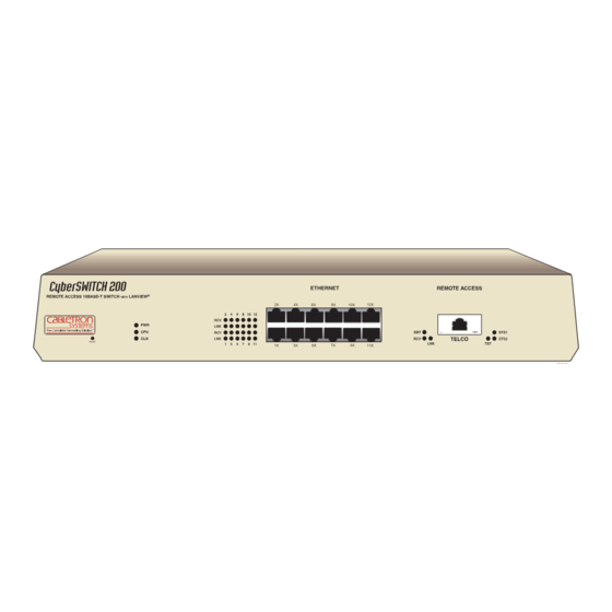
Page 32: Port Descriptions
Ethernet twisted pair ports 1 through 12. Table 3-1 Ethernet Twisted Pair Ports (1-12) Pin Number Signal Name Twisted Pair Transmit + Twisted Pair Transmit - Twisted Pair Receive + Ground Ground Twisted Pair Receive - Ground Ground CSX200 Installation Guide... -
Page 33: 10Base-T Lan Configuration
10BASE-T LAN Configuration This section contains the procedures for connecting a UTP segment from the 10BASE-T network or other devices to the CSX200. Ports 1 through 12 on the CSX200 have RJ45 connectors for UTP connections. Connecting UTP Cables to Ports 1 Through 12 Before connecting a segment to the CSX200, check each end of the segment to verify wire crossover. - Page 34 Figure 3-2 Cable Pinouts - (RJ45) Crossover Cable Check that the twisted pair connection meets the dB loss and cable specifications outlined 10BASE-T LAN If a link is not established, contact Cabletron Systems Technical Support. Refer to Help Chapter 1, Introduction, for details.
-
Page 35: Chapter 4 Installation
Installation This chapter shows you how to connect your CSX200 to the network. Ensure that the network meets the guidelines and requirements outlined in before installing your CSX200. Unpacking the CSX200 Remove the shipping material from the box and carefully remove the CSX200. Visually inspect the CSX200. -
Page 36: Removing The Csx200 Cover
To remove the chassis cover, proceed as follows: • If the CSX200 is installed, unplug the power cord from the rear of the CSX200 chassis. Before disconnecting any network cables, mark them according to their associated port numbers. This will make reinstallation easier. -
Page 37: Installing A Wpim
CAUTION When removing an existing WPIM, make sure to pull the module straight out to avoid damaging the connector. CAUTION To install a WPIM into the CSX200, refer to CSX200 Installation Guide Chassis Cover Chassis on page 4-6, are met. - Page 38 Remove the blank faceplate from the appropriate WPIM slot. • Orient the WPIM as shown in the WPIM connector pins on the CSX200. • Press down firmly on the WPIM until the pins slide all the way into the connector. Ensure that the WPIM seats flush on the standoffs.
-
Page 39: Comp/Encr Module Installation
Carefully insert the connector pins of the CSX200-COMP/ENCR module into the CSX200 D-type connector. • Press down firmly on the CSX200 COMP/ENCR module until the pins fit all the way into the connector. • Secure the CSX200-COMP/ENCR with the standoff screws supplied with the CSX200-COMP/ENCR module. -
Page 40: Installing The Csx200
Locate the six round rubber feet included with your CSX200, and peel the paper backing off the round rubber feet. Place one rubber foot near each of the four corners of the CSX200, and evenly space the remaining two near the center. -
Page 41: Rackmount Installation
Cabletron Systems offers an accessory kit that includes rackmount brackets, mounting screws, and a strain-relief bracket for cable management. The accessory kit is not included with the CSX200, but can be purchased separately from Cabletron Systems as part number CSX200-ACCY-KIT. -
Page 42: Attaching The Strain-Relief Bracket
• 8-32 x 1/4-inch, pan-head screws (4) • 8-32 x 3/8-inch, pan-head screws (4) Do not use any screws other than those supplied with the CSX200-ACCY-KIT to perform the following procedures. CAUTION Attaching the Strain-Relief Bracket Attach the strain-relief bracket to the front of the CSX200 as follows: •... -
Page 43: Attaching The Rackmount Brackets
Locate the four 8-32 x 1/4-inch screws and the two rackmount brackets in the CSX200-ACCY-KIT package. • Using the four 8-32 x 1/4-inch screws, attach the rackmount brackets to the bottom of the CSX200 as shown in Figure Figure 4-7 Installing the Rackmount Brackets CSX200 Installation Guide 4-7, below. -
Page 44: Installing The Csx200 In A 19-Inch Rack
Plug the other end of the power cord into a grounded wall outlet. Verify that the PWR LED is on, indicating that the CSX200 is receiving power. After the CSX200 runs a self test, the CPU LED blinks green indicating normal operation. If the LED remains red, the processor is faulty;... -
Page 45: Chapter 5 Troubleshooting
CSX200 to diagnose power failures, collisions, cable faults and link problems. the front panel LEDs. Table states. If you are having difficulty installing and configuring the CSX200, take the following steps: • Review your CSX200 QuickSTART Guide to insure proper installation. •... - Page 46 Chapter 5: Troubleshooting Receive (RCV) Link (LNK) Transmit (XMT) Receive (RCV) Link (LNK) Test Table 5-2 CSX200 LAN LED States Color State Not receiving traffic AMBER (flashing) Receiving traffic Link does not exist GREEN NORMAL, link exists Table 5-3 CSX200 WAN LED States...
- Page 47 Table 5-4 CSX200 WAN LED States for STS 1 WPIM T1, DI, and E1 SYNC HDSL Table 5-5 CSX200 WAN LED States for STS 2 WPIM T1, DI, and E1 SYNC HDSL CSX200 Installation Guide Color State Normal or port disabled...
-
Page 48: Troubleshooting Csx200 Hardware
Troubleshooting CSX200 Hardware Power (PWR) LED is OFF • Check that the power connection is firmly attached to the back panel of the CSX200, and the other end to an active power source. Processor (CPU) LED is OFF If the CPU stays OFF for an extended amount of time, and the power (PWR) light remains on, the CPU is in an unknown state. -
Page 49: Troubleshooting The Wan
The WAN interface is configured, but there is no signal indicating that a valid connection is present on the WAN interface. • Check that the CSX200 and the device at the other end of the segment are powered up. • Use QuickSET or Local Management to make sure that both WAN interfaces, local and remote, are configured correctly. -
Page 50: Status 1 (Sts1) Led Is Red
Use QuickSET or Local Management to make sure that the WAN interface on the Remote device is configured correctly. Status 1 (STS1) LED is RED WPIM-T1, WPIM-E1, or WPIM-DI Installed in CSX200 is in RED Alarm Mode A RED alarm indicates that the WAN connection is not receiving proper framing or has lost framing. -
Page 51: Status 1 (Sts1) Led Is Amber
The Port is operating normally. Request to Send (RTS) has been activated by your WAN device. • Use QuickSET or Local Management to make sure that the WAN interface on the local device is configured properly. • Verify the cabling being used between the CSX200 and the CSU/DSU. CSX200 Installation Guide Troubleshooting the WAN... -
Page 52: Status 2 (Sts2) Led Is Off
Use QuickSET or Local Management to make sure that the WAN interface on the Remote device is configured correctly. Status 2 (STS 2) LED is RED WPIM-HDSL Installed in CSX200 WPIM-HDSL is configured for either Full T1 and the WPIM is not able to establish synchronization on Loop 2 with the remote HDSL circuit. -
Page 53: Status 2 (Sts2) Led Is Amber
Status 2 (STS2) LED is AMBER WPIM-T1, WPIM-E1, or WPIM-DI Installed in CSX200 The device is in Yellow alarm mode. A Yellow alarm indicates that the CSX200 is receiving proper framing from the Telco, but the Telco is not receiving proper framing. -
Page 54: Test (Tst) Led Is Amber (Blinking)
Check that your LAN cable is wired correctly and each end securely plugged in. • Make sure that an IP route exists between your local PC and the CSX200. The PC and CSX200 must be on the same IP subnetwork or the CSX200 must be reachable through a router on your LAN. - Page 55 Check that you have seeded the routing table, if RIP is not allowed to flow on the WAN link. • Be sure to reboot if you have made any IP address, control or protocol option changes. CSX200 Installation Guide Investigating Software Configuration Problems 5-11...
- Page 56 Chapter 5: Troubleshooting 5-12 CSX200 Installation Guide...
-
Page 57: Wpim-T1
For example: 9372095-3 denotes a 3 foot cable; 9372095-3M denotes a 3-meter cable. WPIM-T1 This section provides the Cabletron Systems part number and connector specifications for WPIM-T1 interface cables. Table A-1 provides connector type and part number information. - Page 58 Receive Ring Receive Tip Not Used Transmit Ring Transmit Tip Not Used Shield Ground Shield Ground Table A-4 Network Pin Assignments Signal Receive Ring Receive Tip Not Used Transmit Ring Transmit Tip Not Used Not Used Not Used CSX200 Installation Guide...
-
Page 59: Wpim-Sy
WPIM-SY This section provides the Cabletron Systems part number and connector specifications for the WPIM-SY interface cables. Table A-5 provides the cable and interface types, electrical types, and part numbers for the WPIM-SY. Cable and Interface Type RS449 V.35 RS232 X.21... -
Page 60: Eia-449
MNEMONIC Send Data A Send Data B Receive Data A Receive Data B Clear to Send A Clear to Send B Request to Send A Send Timing A Send Timing B Receive Timing A Receive Timing B CSX200 Installation Guide... -
Page 61: V.35
MNEMONIC Transmit Data A Transmit Data B Receive Data A Receive Data B Clear to Send A Request to Send A CSX200 Installation Guide PAIR NAME SHIELD 20 Receive Common Table A-8 V.35 Interface Cable Assembly Description EIA-530A ALT A to V.35... - Page 62 Timing B Receiver Signal Timing A Receiver Signal Timing B Transmitter Signal Timing A Transmitter Signal Timing B Calling Indicator Test Indicator Data Set Ready Data Terminal Ready Loopback Maintenance Local Loopback DRAIN Signal Common Signal Common CSX200 Installation Guide...
-
Page 63: Eia-232
Request to Send Transmit Signal Timing Receive Signal Timing Transmit Signal Timing Remote Loopback Local Loopback Signal Common Signal Common CSX200 Installation Guide Table A-10 EIA-232 Interface Cable Assembly Description EIA-530A ALT A to EIA-232 NAME PIN PIN Transmit Data Receive Data... -
Page 64: X.21
Sub DB 26-pin male DB-15 pin male Connector 2 X.21 DIRECT NAME MNEMONIC Transmit A Transmit B Receive A Receive B Indication A Indication B Control A Control B Signal Element Timing A Signal Element Timing B DRAIN Signal Ground CSX200 Installation Guide... -
Page 65: Eia-530, Eia-530 Alt A, Eia-530 A, And Eia-530 A Alt A
Receive Data B Clear to Send A Clear to Send B Request to Send A Request to Send B CSX200 Installation Guide Cable Assembly Description EIA-530A ALT A to EIA-530 EIA-530A ALT A to EIA-530 ALT A EIA-530A ALT A to EIA-530A... - Page 66 Transmit Signal Timing B Receive Signal Timing A Receive Signal Timing B Transmit Signal Timing A Transmit Signal Timing B Local Loopback Test Mode DCE Ready DTE Ready DRAIN Signal Common Signal Common Signal Common Ring Indicator CSX200 Installation Guide...
-
Page 67: Wpim-Dds
WPIM-DDS This section provides Cabletron Systems part number and connector specifications for the WPIM-DDS interface cable. The WPIM-DDS has one RJ45 port for a direct connection to a single Digital Data Service (DDS) circuit. Table A-16 provides cable and interface type, and part number information for the WPIM-DDS... -
Page 68: Wpim-E1
Appendix A: WPIM Cable Specifications WPIM-E1 This section provides the Cabletron Systems part number and connector specifications for the WPIM-E1 interface cable. Table A-18 shows the WPIM-E1 connector number, cable and interface type, connector type and part number information. Table A-18 WPIM-E1 Connector Information... - Page 69 Table A-20 provides WPIM-E1 DTE interface cable pin assignments. Table A-21 provides WPIM-E1 RJ45 network interface cable pin assignments. CSX200 Installation Guide Table A-20 DTE Interface Signal Receive Ring Receive Tip Shield Ground Transmit Ring Transmit Tip Shield Ground Not Used...
-
Page 70: Wpim-Di
Appendix A: WPIM Cable Specifications WPIM-DI This section provides Cabletron Systems part number and connector specifications for the WPIM-DI interface cables. Table A-22 shows the connector number, cable assembly description, cable and interface type, connector type and part number information for the WPIM-DI interface. -
Page 71: Wpim-Hdsl
WPIM-HDSL This section provides connector specifications for the WPIM-HDSL interface cables. provides pin assignments for the RJ-45 network interface connector. Table A-25 WPIM-HDSL Network Interface Cable Pin Assignments CSX200 Installation Guide Table A-24 WPIM-DI Drop and Insert Signal Transmit Ring... - Page 72 Appendix A: WPIM Cable Specifications A-16 CSX200 Installation Guide...
- Page 73 Specifications and Standards Compliance This chapter contains hardware specifications, and safety and compliance standards for the CSX200, and for the individual WPIMs that can be configured with this device. WAN Interface LAN Interface Other Interfaces Processor Width Height Depth Weight...
-
Page 74: Appendix Bspecifications And Standards Compliance
15, EN 55022, EN 50082-1, 89/336/EEC, AS/NZS 3548, CSA C108.8, and VCCI V-3. Individual WPIM Regulatory Compliance The following sections provide regulatory compliance standards for the WPIM-TI, WPIM-SY, WPIM-DDS, WPIM-E1, WPIM-DI, WPIM-S/T, and the WPIM-HDSL. Cabletron Systems reserves the right to change these specifications at any time without notice. WPIM-T1 This section describes the environmental specifications and safety and approval requirements for... -
Page 75: Wpim-Sy
This unit meets the EMC requirements of FCC Part 15, CSA108.8, and VCCI V-3. (EMC) — NEBS — This unit meets a minimum of Level 1 NEBS requirements in accordance with Bellcore SR 3580. FCC Part 68, CS-03. TELECOM — CSX200 Installation Guide Individual WPIM Regulatory Compliance... -
Page 76: Wpim-E1
This unit meets a minimum of Level 1 NEBS requirements in accordance with Bellcore GR 1089. This unit meets the EMI requirements of EN 55022, This unit meets the EMI requirements of FCC Part This unit meets the EMC requirements of FCC CSX200 Installation Guide... - Page 77 FCC Part 68 - User’s Information for CSX200 The following instructions are to ensure compliance with the Federal Communications Commission (FCC) Rules, Part 68: All connections to the WPIM-T1, WPIM-DI and WPIM-DDS must be made using standard plugs and jacks.
- Page 78 Appendix C: FCC Part 68 - User’s Information for CSX200 If the telephone company alters their equipment in a manner that will affect use of this device, they must give you advance warning so as to give you the opportunity for uninterrupted service.
- Page 79 • The encoded analog and billing protection is factory set and is not under the control of the customer. CSX200 Installation Guide FCC Part 68 - User’s Information for CSX200 , of (Customer Name) (Telephone Number) Subrate digital services. The...
- Page 80 Appendix C: FCC Part 68 - User’s Information for CSX200 I attest that the operator(s) maintainer(s) of the digital CPE responsible for the establishment, maintenance and adjustment of the encoded analog content and billing information has (have) been trained to perform these functions by successfully completing one of the following: Check appropriate one(s).
- Page 81 Techniques used to reduce the number of bits transferred across the communication links that represent the actual data bits. Compression is used to optimize use of WAN links and speed data transmission. CSX200 Installation Guide Feature providing the capability of adjusting the bandwidth (opening...
- Page 82 TCP/IP. An IP address consists of four octets separated with periods defining network, optional subnet and host sections. A proprietary Network layer protocol developed by Novell IPX (Internet Packet Exchange) — and used in NetWare networks. CSX200 Installation Guide...
- Page 83 files and other network services. Layer 3 of the OSI reference model that provides the protocol routing Network Layer — function. Node — Refers to a termination point for communication links; entity that can access a network. CSX200 Installation Guide...
- Page 84 file servers, CD-ROM drives and modem pools. An echo message, available within the TCP/IP protocol suite, A Data Link layer protocol that provides asynchronous and Protocols used in IP and IPX for broadcasting open path Protocol used in IPX for broadcasting information about CSX200 Installation Guide...
- Page 85 Bridges are unknown to the end nodes. User Datagram Protocol. A connectionless protocol used to pass packets across an UDP — internet network, requiring no handshaking between source and destination. CSX200 Installation Guide...
- Page 86 Frames sent out by servers to clients, under IPX, to verify that clients are Watchdog Frames — still logged on. Wide Area Network — A communications network that is geographically dispersed thus requiring links provided by communications carriers. Computer or terminal used by the systems administration or user. Workstation — CSX200 Installation Guide...
- Page 87 COMP/ENCR installation Daughter Board Dynamic Host Configuration Protocol (DHCP) EMC B-2, B-3, EMI B-3, Firmware Data Compression Flash EEPROMs Getting help CSX200 Installation Guide Index Hardware specs HDLC Help related manuals High-bit rate Digital Subscriber Line (HDSL) IEEE 802.1d bridging IEEE 802.3 Ethernet...
- Page 88 2-12 super-user 2-12 Software and firmware upgrades technical support Troubleshooting bridging 5-10 power software 5-10 TCP/IP routing 5-11 Worksheets (network info) WPIMs WPIM-DDS 2-2, WPIM-DI 2-2, WPIM-E1 2-2, WPIM-HDSL 2-2, WPIM-SY 2-2, WPIM-T1 2-1, Index-2 2-15 CSX200 Installation Guide...
Need help?
Do you have a question about the CSX200 CyberSWITCH and is the answer not in the manual?
Questions and answers