Table of Contents
Advertisement
Quick Links
Advertisement
Table of Contents

Related Manuals for Cabletron Systems MMAC-Plus 9H421-12


Summary of Contents for Cabletron Systems MMAC-Plus 9H421-12
- Page 1 SmartSwitch 9000 9H421-12, 9H422-12 and 9H429-12 User’s Guide 9031928-03...
- Page 3 Notice Notice Cabletron Systems reserves the right to make changes in specifications and other information contained in this document without prior notice. The reader should in all cases consult Cabletron Systems to determine whether any such changes have been made. The hardware, firmware, or software described in this manual is subject to change without notice.
-
Page 4: Fcc Notice
Notice FCC Notice This device complies with Part 15 of the FCC rules. Operation is subject to the following two conditions: (1) this device may not cause harmful interference, and (2) this device must accept any interference received, including interference that may cause undesired operation. NOTE: This equipment has been tested and found to comply with the limits for a Class A digital device, pursuant to Part 15 of the FCC rules. -
Page 5: Declaration Of Conformity
DECLARATION OF CONFORMITY Application of Council Directive(s): Manufacturer’s Name: Manufacturer’s Address: European Representative Name: European Representative Address: Conformance to Directive(s)/Product Standards: Equipment Type/Environment: We the undersigned, hereby declare, under our sole responsibility, that the equipment packaged with this notice conforms to the above directives. Manufacturer Mr. -
Page 6: Safety Information
Notice Safety Information CLASS 1 LASER TRANSCEIVERS The 9H421-12, 9H429-12 and FE-100FX are Class 1 Laser Product The 9H421-12, 9H429-12 and FE-100FX use a Class 1 Laser transceiver. Read the following safety information before installing or operating The Class 1 laser transceivers use an optical feedback loop to maintain Class 1 operation limits. - Page 7 Notice Safety Information CLASS 1 LASER TRANSCEIVERS Laser Radiation and Connectors When the connector is in place, all laser radiation remains within the fiber. The maximum amount of radiant power exiting the fiber (under normal conditions) is -12.6 dBm or 55 x 10 watts.
- Page 8 Notice...
-
Page 9: Table Of Contents
Installing the SmartSwitch 9000 Module Unpacking the Module... 2-1 Installing an FEPIM ... 2-1 User Accessible Components ... 2-2 Installing the Module into the SmartSwitch 9000 Chassis... 2-6 The Reset Switch ... 2-8 Chapter 3 Operation FENIB... 3-3 SmartSwitch ASIC... 3-3 Traditional Switch... - Page 10 Contents Physical... 5-2 Dimensions ... 5-2 Weight... 5-2 Environment ... 5-2 Appendix A FEPIM Specifications FE-100TX...A-1 FE-100FX...A-2 viii...
-
Page 11: Chapter 1 Introduction
The FEPIM port accepts either the FE-100TX, for use with twisted pair copper, or the FE-100FX, for use with mulitmode fiber optic cabling. The 9H421-12 is a twelve port switch module, equipped with twelve 100BASE-FX multimode fiber (MMF) ports. The 9H429-12 is a twelve port switch module, equipped with twelve 100BASE-FX single mode fiber (SMF) ports. - Page 12 Introduction Management The 9H421-12, 9H422-12 and the 9H429-12 modules support SNMP for local and remote management. Local management is provided through the RS-232 Com ports on the SmartSwitch 9000 Environmental Module using a standard VT-220 terminal or emulator. Remote management is possible through Cabletron’s SPECTRUM or any SNMP compliant management tool as well as telneting to the module.
- Page 13 Introduction Management Information Base (MIB) Support The 9H421-12, 9H422-12 and the 9H429-12 modules provide MIB support including: • Cabletron Fast Ethernet MIB • IETF MIB II • IETF Bridge MIB • RMON • a host of Cabletron Enterprise MIBs For a complete list of supported MIBs, refer to the release notes provided in the NOTE 9H421-12, 9H422-12 and the 9H429-12 module packages.
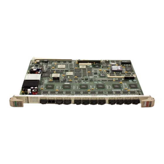
- Page 14 Introduction FAST ENET FAST ENET FAST ENET 9H421-12 9H429-12 9H422-12 Figure 1-1. The 9H421-12, 9H429-12 and 9H422-12 Modules...
-
Page 15: Related Manuals
Related Manuals The manuals listed below should be used to supplement the procedures and technical data contained in this manual. SmartSwitch 9000 Installation Guide SmartSwitch 9000 9C300-1 Environmental Module User’s Guide SmartSwitch 9000 9C214-1 AC Power Supply User’s Guide INB Terminator Modules Installation Guide SmartSwitch 9000 Module Local Management User’s Guide Getting Help For additional support related to this device or document, contact the Cabletron Systems Global Call... - Page 16 Introduction...
-
Page 17: Installing The Smartswitch 9000 Module
Installing the SmartSwitch 9000 Module The 9H421-12, 9H422-12 and the 9H429-12 modules each occupy a single slot in the SmartSwitch 9000 chassis. Install any of these modules by following the steps starting below. Unpacking the Module 1. Carefully remove the module from the shipping box. (Save the box and packing materials in the event the module must be reshipped.) 2. -
Page 18: User Accessible Components
User Accessible Components Figure 2-2 shows the various components that are accessible to the user. These consist of an eight position DIP switch (explained below), replaceable PROMs and sockets for RAM. These will be used for future upgrades. Instructions for installing the components will be supplied with the upgrade kit. - Page 19 SMB 10 FEPIM Connector Flash CNXSTATS Connector Boot Prom DRAM Dip Switches Figure 2-2. 9H422-12 User Accessible Components Installing the SmartSwitch 9000 Module...
- Page 20 DRAM Dip Switches Figure 2-3. 9H421-12 and 9H429-12 User Accessible Components An eight position DIP switch is located on the module card as shown in Figure 2-2 and Figure 2-3. The function of the switches are listed in Table 2-1.
- Page 21 See the Cautions at the end of this table. Switch Caution: Do not toggle Switch 8 unless you intend to reset the user configured passwords to their factory default settings. CAUTION Caution: Do not toggle Switch 7 unless you intend to reset the user parameters to the factory default settings.
-
Page 22: Installing The Module Into The Smartswitch 9000 Chassis
Installing the SmartSwitch 9000 Module Installing the Module into the SmartSwitch 9000 Chassis To install the SmartSwitch 9000 module, follow the steps below: The INB Terminator Modules must be installed on the rear of the chassis before powering up this module. Refer to the INB Terminator Modules Installation Guide for NOTE information and installation procedure. - Page 23 Metal Back-Panel Module Guides Warning: Ensure that the circuit card is between the card guides. Lock down the top and bottom plastic tabs at the same time, applying even pressure. Figure 2-4. Installing the 9H421-12, 9H422-12 and 9H429-12 Modules Installing the SmartSwitch 9000 Module Plastic Tab Jack for ESD Wrist Strap...
-
Page 24: The Reset Switch
Installing the SmartSwitch 9000 Module The Reset Switch The Reset switch is located under the top plastic tab as shown in Figure 2-5. It serves two functions: • Pressing the reset switch twice within three seconds causes the processor (i960) to reset. -
Page 25: Chapter 3 Operation
FE-100FX, for use with mulitmode fiber optic cabling. The 9H421-12 is a twelve port switch module, equipped with twelve multimode fiber 100BASE-FX ports. The 9H429-12 is a twelve port switch module, equipped with twelve single mode fiber 100BASE-FX ports. - Page 26 Data packets are then converted from the canonical format to the proper format for the interface destination whether it is a front panel port, or connection to the INB. Diagnostic i960 Controller Processor DC/DC Convertor Smart Switch ASIC Figure 3-1. Packet Flow SMB 1 SMB 10...
-
Page 27: Fenib
INB backplane, and LAN/WAN interfaces on the front panel of SmartSwitch 9000 modules. The SmartSwitch ASIC can operate in two modes; as a traditional switch or as a SecureFast Switch (SFS). Traditional Switch When operating as a traditional switch, the SmartSwitch ASIC makes filtering/... -
Page 28: I960 Core
Operation i960 Core The i960 core provides the SNMP protocol stacks, to support industry standard MIBs. Additionally, Cabletron enterprise extension MIBs are supported for each media type. Advanced management services, such as telnet and network address to MAC address mapping, are also provided by the i960 core. The Host engine sends and receives packets via the CPU’s SmartSwitch ASIC Interface. -
Page 29: Smb-10 Bus
SMB-10 Bus The SMB-10 is a 10 Mbps management bus located within the SmartSwitch 9000. This bus is used for inter-chassis communication of modules as well as serving as a side-band management channel into the SmartSwitch 9000. The SMB-10 is externalized from the chassis via an optional Ethernet Port Interface Module (EPIM) located on the front of the Environmental Module. -
Page 30: Inb Interface
Operation INB Interface The INB Backplane is designed to transport fixed length data blocks between modules in the SmartSwitch 9000 using a Time Division Multiplexing (TDM) design. The SmartSwitch 9000 INB bus delivers 2.0 Gbps of true data bandwidth with all control and management communication being serviced on the 8 bit out- of-band bus. -
Page 31: Lanview Leds
LANVIEW LEDs The front panel LANVIEW LEDs indicate the status of the module and may be used as an aid in troubleshooting. Figure 4-1 and Figure 4-2 show the LANVIEW LEDs of the 9H421-12, 9H422-12 and the 9H429-12 modules. INB Receive FAST ENET 9H422-12 System Status... - Page 32 LANVIEW LEDs INB Receive Figure 4-2. 9H421-12 and 9H429-12 LANVIEW LEDS FAST ENET Port Receive System Status INB Transmit Port Transmit...
- Page 33 The function of the two System Status LEDs, System Management Bus (SMB) and CPU (Central Processing Unit), are listed in Table 4-1. Table 4-1. System Status (SMB and CPU) LEDs LED Color State Green Functional Yellow Testing Yellow (Blinking) Crippled Yellow/Green Booting Reset...
- Page 34 LANVIEW LEDs The functions of the INB Transmit LEDs are listed in Table 4-3. LED Color Green (Flashing) Yellow (Blinking) Red (Flashing) The functions of the Port Receive LEDs are listed in Table 4-4. LED Color Green Green (Flashing) Yellow (Flashing) The functions of the Port Transmit LEDs are listed in Table 4-5.
-
Page 35: Chapter 5 Specifications
Specifications Technical Specifications Intel i960 RISC based microprocessor Memory 4 Mb Flash Memory (expandable to 16 Mb) 16 Mb DRAM (expandable to 48 Mb 2 Mb Packet RAM Additional 64K buffer per port Standards IEEE 802.3u Network Interface 11 100BASE-TX and 1 Cabletron FEPIM (for the 9H422-12) 12 Multi-mode 100BASE-FX (for the 9H421-12) 12 Single Mode 100BASE-FX (for the 9H429-12) Safety... -
Page 36: Service
Specifications This equipment meets the safety requirements of: • UL 1950 • CSA C22.2 No. 950 • EN 60950 • IEC 950 • EMI Requirements of FCC Part 15 Class A • EN 55022 Class A • VCCI Class I •... -
Page 37: Appendix A Fepim Specifications
The slide switch on the FE-100TX determines the crossover status of the cable pairs. If the switch is on the X side, the pairs are internally crossed over. If the switch is on the = side, the pairs are not internally crossed over. Figure A-1 shows the pinouts for the FEPIM-100TX in both positions. -
Page 38: Fe-100Fx
FEPIM Specifications FE-100FX The FE-100FX shown in Figure A-2 supports multimode fiber optic cabling. The FE-100FX is equipped with an SC style port. Table A-1 lists the specifications for the FE-100FX. Cable Type 50/125 µm fiber 62.5/125 µm fiber 100/140 µm fiber The transmitter power levels and receive sensitivity levels listed are Peak Power Levels after optical overshoot.
Need help?
Do you have a question about the MMAC-Plus 9H421-12 and is the answer not in the manual?
Questions and answers