Table of Contents
Advertisement
Quick Links
MP141E
L-509 Stage
User Manual
Version: 1.1.0
PI miCos GmbH, Freiburger Strasse 30, 79427 Eschbach, Germany
Phone +49 7634 5057-0, Fax +49 7634 5057-99, Email info@pimicos.ws, www.pi.ws
Date: 17.03.2017
This document describes the following stages:
L-509.x0DG10:
with gear motor and rotary encoder
L-509.x0SD00:
with 2-phase stepper motor, without encoder
L-509.xASD00:
with 2-phase stepper motor and linear encoder
L-509.x0AD10:
with Active Drive and rotary encoder
L-509.x4AD00:
with Active Drive and linear encoder
x stands for travel range:
1 = 26 mm
2 = 52 mm
4 = 102 mm
Advertisement
Table of Contents

Related Manuals for PI L-509 Series


Summary of Contents for PI L-509 Series
- Page 1 Active Drive and linear encoder x stands for travel range: 1 = 26 mm 2 = 52 mm 4 = 102 mm PI miCos GmbH, Freiburger Strasse 30, 79427 Eschbach, Germany Phone +49 7634 5057-0, Fax +49 7634 5057-99, Email info@pimicos.ws, www.pi.ws...
- Page 2 NEXACT®, Picoactuator®, PInano®, NEXSHIFT, PITOUCH, PIMag®, PIHera, Q-Motion® © 2017 Physik Instrumente (PI) GmbH & Co. KG, Karlsruhe, Germany. The text, photographs and drawings in this manual are protected by copyright. With regard thereto, Physik Instrumente (PI) GmbH & Co. KG retains all the rights.
-
Page 3: Table Of Contents
Contents About this Document Objective and Target Audience of this User Manual..........1 Symbols and Typographic Conventions..............1 Definition ........................2 Figures ........................2 Other Applicable Documents ..................3 Downloading Manuals ....................3 Safety Intended Use ......................5 General Safety Instructions ..................5 Organizational Measures .................... - Page 4 Start-Up General Notes on Start-Up ..................33 Starting Up the stage ....................36 6.2.1 L-509 Entries in the Stage Database of PI ............ 36 6.2.2 Operating Parameters of the Models with DC Motor ......... 37 6.2.3 Operating Parameters of the Models with Stepper Motor ......38 Maintenance General Notes on Maintenance ................
-
Page 5: About This Document
1 About this Document About this Document In this Chapter Objective and Target Audience of this User Manual ..............1 Symbols and Typographic Conventions ..................1 Definition ............................2 Figures ............................2 Other Applicable Documents ......................3 Downloading Manuals ........................3 Objective and Target Audience of this User Manual This manual contains information on the intended use of the L-509. -
Page 6: Definition
1 About this Document Symbol/ Meaning Label Action consisting of several steps whose sequential order must be observed Action consisting of one or several steps whose sequential order is irrelevant List item p. 5 Cross-reference to page 5 RS-232 Labeling of an operating element on the product (example: socket of the RS-232 interface) -
Page 7: Other Applicable Documents
1 About this Document Other Applicable Documents The devices and software tools that are mentioned in this documentation are described in their own manuals. Product Document Stages with electric motors MP146EK Short instructions for stages with electric motors C-863.11 DC Motor Controller MS205E User Manual C-663.11 Stepper Motor Controller MS208E User Manual... - Page 8 1 About this Document Downloading manuals 1. Open the website www.pi.ws. 2. If access to the manuals is protected by a password: a) Click Login. b) Log in with the user name and password. 3. Click Search. 4. Enter the product code up to the period (e.g., P-882) or the product family (e.g., PICMA®...
-
Page 9: Safety
2 Safety Safety In this Chapter Intended Use ..........................5 General Safety Instructions......................5 Organizational Measures ....................... 6 Intended Use The L-509 is a laboratory device as defined by DIN EN 61010. It is intended for indoor use and use in an environment that is free of dirt, oil and lubricants. In accordance with its design and realization, the L-509 is intended for single-axis positioning, adjusting and shifting of loads at different velocities. -
Page 10: Organizational Measures
2 Safety Organizational Measures User manual Always keep this user manual available with the L-509. The latest versions of the user manuals are available for download (p. 3) on our website. Add all information from the manufacturer to the user manual, for example supplements or technical notes. -
Page 11: Product Description
3 Product Description Product Description In this Chapter Model Overview ..........................7 Product View ..........................9 Direction of Motion ........................9 Product Labeling .......................... 10 Scope of Delivery ......................... 11 Accessories ........................... 12 Suitable Controllers ........................12 Technical Features ........................13 Model Overview Classification of the stages All models are electromotive linear positioning stages with precision leadscrew. - Page 12 3 Product Description Detailed Model Overview Order number Product name L-509.10AD10 Precision Linear Stage, 85 mm Wide, ActiveDrive DC Motor, 26 mm (1") Travel Range, Optical Limit Switches L-509.10DG10 Precision Linear Stage, 85 mm Wide, DC Gear Motor, 26 mm (1") Travel Range, Optical Limit Switches L-509.10SD00 Precision Linear Stage, 85 mm Wide, 2-Phase Stepper Motor, 26 mm (1")
-
Page 13: Product View
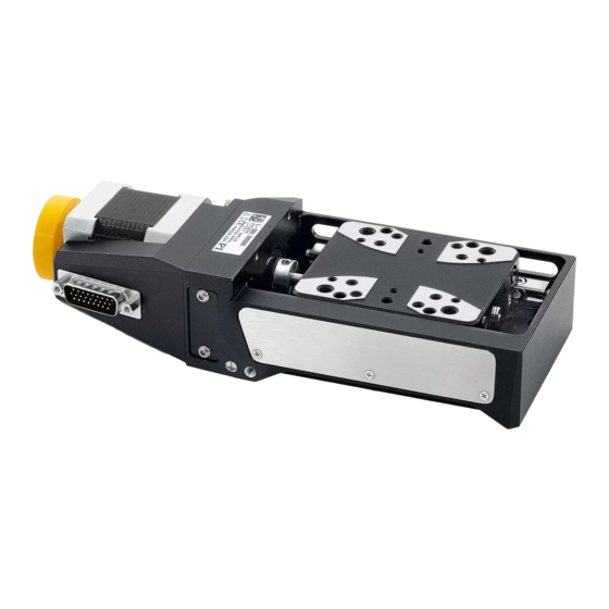
3 Product Description Product View Figure 1: Parts of the L-509, examples: L-509.2ASD00 (left), L-509.20AD10 (right) Motor Sensor unit (only L-509.xASD00 and L-509.x4AD00 models) Motion platform Base body Sensor connection (Sub-D 9 panel plug; only L-509.xASD00 models) Motor connection (for L-509.x0SD00 / L-509.xASD00 / L-509.x0DG10: Panel plug HD Sub-D 26; for L-509.x0AD10 / L-509.x4AD00: Sub-D 15 panel plug) Vibration absorber (only L-509.x0SD00 and L-509.xASD00 models) Power supply connection (M8 panel plug 4-pin, only L-509.x0AD10 and L-509.x4AD00 models) -
Page 14: Product Labeling
2, 7 Warning sign "Observe manual!" 2, 8 Country of origin: Germany Country of origin 2, 10 CE conformity mark 2, 11 WWW.PI.WS Manufacturer's address (website) 2, 12 Old equipment disposal Sensor Linear encoder connection (only L-509.xASD00 models) 4, 5 Warning sign "Risk of crushing": Reference to... -
Page 15: Scope Of Delivery
3 Product Description Scope of Delivery Item number Component L-509 model. L-509.xxxxxx Stage according to order (p. x0AD10 x4AD00 x0DG10 x0SD00 xASD00 Motor cable and, if applicable, sensor cable according to the ordered controller 62345070 (for Screw set for mounting the L-509.1xxxxx) stage or 62345016... -
Page 16: Accessories
Daisy chain interface network SMC Hydra RS-232, .xASD00 TCP/IP PC software is included in the scope of delivery of the controllers from PI. The operation of the controllers is described in the corresponding user manuals. Version: 1.1.0 MP141E L-509 Stage... -
Page 17: Technical Features
3 Product Description Technical Features 3.8.1 Encoder The L-509.x0SD00 models are not equipped with an encoder. Linear encoder The L-509.x4AD00 and L-509.xASD00 models are equipped with an optical linear encoder. For the encoder resolution, refer to the table in the "Specifications" section (p. 47). Optical linear encoders measure the actual position directly (direct metrology). -
Page 19: Unpacking
2. Compare the contents with the items listed in the contract and the packing list. 3. Inspect the contents for signs of damage. If parts are missing or you notice signs of damage, contact PI immediately. 4. Keep all packaging materials in case the product needs to be returned. -
Page 21: Installation
5 Installation Installation In this Chapter General Notes on Installation ...................... 17 Mounting the L-509 onto a Surface ..................... 19 Connecting the L-509 to the Protective Earth Conductor ............22 Affixing the Load to the L-509 ...................... 24 Setting Up a Multi-Axis System ....................25 Connecting the L-509 to the Controller .................. - Page 22 5 Installation NOTICE Heating up of the L-509 during operation! The heat produced during operation of the L-509 can affect your application. Install the L-509 so that your application is not affected by the dissipating heat. INFORMATION For optimum repeatability, all components must be firmly affixed to each other. INFORMATION The use of locating pins during mounting reduces deviations from the ideal alignment of the stage.
-
Page 23: Mounting The L-509 Onto A Surface
5 Installation Mounting the L-509 onto a Surface NOTICE Protruding screw heads! Protruding screw heads can damage the L-509. Ensure that the screw heads do not protrude from countersunk holes so that they do not interfere with the stage motion. NOTICE Warping of the L-509 due to mounting on uneven surfaces! Mounting the L-509 on an uneven surface can warp the L-509. - Page 24 5 Installation Figure 4: Position of the holes for mounting the stage Figure 5: Position of the locating holes for aligning the stage Requirements You have read and understood the general notes on installation (p. 17). You have provided a suitable surface (for the required position and depth of the holes for accommodating the screws and locating pins, see "Dimensions"...
- Page 25 5 Installation Tools and accessories Mounting accessories, in the scope of delivery (p. 11) − 4 or 8 socket head cap screws, ISO 4762 M4x14 − 2 dowel pins, ISO 8734 - 4 m6 × 12, for use as locating pins Allen wrench AF 3 ...
-
Page 26: Connecting The L-509 To The Protective Earth Conductor
5 Installation Connecting the L-509 to the Protective Earth Conductor INFORMATION It is only necessary to connect the L-509 to the protective earth conductor when both of the following conditions are met: The load on the motion platform of the L-509 must be connected to the protective earth conductor, but it is not possible to connect the protective earth conductor directly to the load. - Page 27 5 Installation Figure 7: Connecting the protective earth conductor (profile view) Base body of the L-509 Flat washer Safety washer Screw Cable lug Protective earth conductor Requirements You have read and understood the general notes on installation (p. 17). Tools and accessories Suitable protective earth conductor: Cross-sectional area of the cable ≥...
-
Page 28: Affixing The Load To The L-509
5 Installation Affixing the Load to the L-509 NOTICE Impermissibly high load on the stage! An impermissibly high load interferes with the motion of the motion platform and can damage the stage. In respect to the mass and mounting type of the load, observe the maximum permissible forces that are allowed to act on the motion platform according to the specification (p. -
Page 29: Setting Up A Multi-Axis System
5 Installation Affixing the Load 1. Align the load so that the selected mounting holes in the motion platform can be used to affix it. If you use locating pins to align the load: a) Insert the locating pins into the locating holes in the platform. b) Place the load on the motion platform so that the locating pins are inserted into the corresponding locating holes on the other side. -
Page 30: Setting Up An Xy System
5 Installation 5.5.2 Setting Up an XY System NOTICE Screws that are too long! Screws and locating pins that are inserted too deeply can damage the lower stage. Observe the depth of the mounting holes in the motion platform (p. 52) of the lower stage. - Page 31 5 Installation Setting up an XY system Figure 9: Moving the platform and mounting the screws Lower stage Upper stage Screw M4x14 L-509 Stage MP141E Version: 1.1.0...
-
Page 32: Setting Up A Z System
5 Installation 1. Allow access to two of the required mounting holes in the base body of the stage. Possible measures: − Temporary start-up of the upper stage (p. 33) and commanding the platform to a suitable position − Moving the motion platform manually (p. 43) 2. - Page 33 5 Installation Requirements You have read and understood the general notes on installation (p. 17). You have read and understood the general notes on setting up a multi-axis system (p. 25). You have accounted for the space required to route cables without bending and according to regulations.
- Page 34 5 Installation 1. Mount the upper stage to the long side of the adapter bracket: a) Align the upper stage so that the motor module points away from the origin of the sides of the adapter bracket; i.e., upwards in the Z system. b) Place the stage on the long side of the adapter bracket so that the mounting holes in the stage and the mounting bracket are covered (see figure above).
-
Page 35: Connecting The L-509 To The Controller
5 Installation Connecting the L-509 to the Controller NOTICE Damage if an incorrect controller or motor cable is connected! Connecting a stage to an unsuitable controller or using an unsuitable motor cable can cause damage to the stage or controller. ... -
Page 36: Connecting The Power Supply To The L-509
5 Installation Connecting the Power Supply to the L-509 Connecting a power supply is only necessary for the L-509.xxADxx models. Requirements The power cord is not connected to the power socket. Tools and accessories Supplied components: − 24 V wide-range-input power supply −... -
Page 37: Start-Up
6 Start-Up Start-Up In this Chapter General Notes on Start-Up ......................33 Starting Up the stage ........................36 General Notes on Start-Up CAUTION Risk of crushing by moving parts! There is a risk of minor injury from crushing between the movable parts of the stage or the load and a fixed part or obstacle. - Page 38 6 Start-Up NOTICE Damage if an incorrect controller or motor cable is connected! Connecting a stage to an unsuitable controller or using an unsuitable motor cable can cause damage to the stage or controller. Only connect a stage to a suitable controller (p. 12). ...
- Page 39 The repeatability of the positioning is only ensured when the reference point switch is always approached from the same side. Controllers from PI fulfill this requirement due to the automatic direction sensing for reference moves to the reference point switch.
-
Page 40: Starting Up The Stage
Configure the controller during start-up using the PC software for the stage used (see user manual of the controller, and the PC software): − If you use a controller from PI: Select the entry in the stage database that exactly fits the stage model (p. 36) used. −... -
Page 41: Operating Parameters Of The Models With Dc Motor
6 Start-Up 6.2.2 Operating Parameters of the Models with DC Motor If you use a DC motor controller from a third-party supplier, it may be necessary to enter operating parameters for adaptation to the stage used. Parameter L-509 model Unit .x0DG10 .x0AD10 .x4AD00... -
Page 42: Operating Parameters Of The Models With Stepper Motor
6 Start-Up 6.2.3 Operating Parameters of the Models with Stepper Motor If you use a stepper motor controller from a third-party supplier, it may be necessary to enter operating parameters to adapt it to the stage used. Parameter L-509.xxSD00 Unit Stage characteristics Max. -
Page 43: Maintenance
7 Maintenance Maintenance In this Chapter General Notes on Maintenance ....................39 Performing a Maintenance Run ....................39 Cleaning the L-509 ........................40 General Notes on Maintenance NOTICE Damage due to improper maintenance! Improper maintenance can lead to misalignment and failure of the L-509. ... -
Page 44: Cleaning The L-509
7 Maintenance Cleaning the L-509 Prerequisites You have disconnected the stage from the controller and the power supply. Cleaning the stage If necessary, clean the surfaces of the stage with a cloth that is lightly dampened with a mild cleanser or disinfectant. -
Page 45: Troubleshooting
Carry out a maintenance run over the entire motions over a long period travel range (p. 39). of time Functional impairment Controller from PI: Controller was replaced. after system Load the parameters from the stage database L-509 has been replaced... - Page 46 PC software. For details, see the user manual of the controller. Motion platform has If you use a controller from PI: triggered the limit switch. 1. Switch on the servo mode for the affected axis again in the PC software.
-
Page 47: Moving The Platform Manually
8 Troubleshooting Moving the Platform Manually INFORMATION It can be necessary to move the motion platform manually to provide access to mounting holes for mounting screws in the base body of the stage. INFORMATION Manual movement of the motion platform of the L-509.x0AD10 / L-509.x4AD00 / L-509.x0DG10 models is not possible. -
Page 49: Customer Service
9 Customer Service Customer Service For inquiries and orders, contact your PI sales engineer or send us an email (mailto:info@pi.ws). If you have questions concerning your system, have the following information ready: − Product codes and serial numbers of all products in the system −... -
Page 51: Technical Data
10 Technical Data Technical Data In this Chapter Specifications ..........................47 Dimensions ..........................52 Tightening Torque for Screws, ISO 4762 - A2 ................55 Pin Assignment ..........................56 10.1 Specifications 10.1.1 Data Table L-509.x4AD00 / L-509.x0AD10 / L-509.x0DG10 L-509.x4AD00 L-509.x0AD10 L-509.x0DG10 Unit Tolerance... - Page 52 10 Technical Data L-509.x4AD00 L-509.x0AD10 L-509.x0DG10 Unit Tolerance Mechanical properties Spindle pitch Gear ratio 2401:81 Load capacity max. Push/pull force max. Permissible lateral force max. Holding force max. Drive properties Motor Type DC motor with DC motor with DC gear motor PWM control PWM control Operating voltage...
- Page 53 10 Technical Data L-509.xASD00 / L-509.x0SD00 L-509.xASD00 L-509.x0SD00 Unit Tolerance Motion and positioning Travel range* 26 / 52 / 102 26 / 52 / 102 Integrated sensor Linear encoder – Sensor resolution rotary – – µm encoder Design resolution 0.001** 0.315*** µm typ.
-
Page 54: Maximum Ratings
10 Technical Data L-509.xASD00 L-509.x0SD00 Unit Tolerance Miscellaneous Operating temperature range 0 to 55 -20 to 65 °C Material Aluminum, steel Aluminum, steel Mass 1.4 / 1.6 / 1.9 1.4 / 1.6 / 1.9 Connector HD Sub-D 26 (motor), HD Sub-D 26 (motor) to Sub-D 9 (linear encoder), Sub-D 15, 3 m cable incl. -
Page 55: Ambient Conditions And Classifications
10 Technical Data 10.1.3 Ambient Conditions and Classifications The following ambient conditions and classifications for the L-509 must be observed: Area of application For indoor use only Maximum altitude 2000 m Relative humidity Max. 80 % for temperatures up to 31 °C Linearly decreasing to 50 % at 40 °C Storage temperature 0 °C to 80 °C... -
Page 56: Dimensions
10 Technical Data 10.2 Dimensions 10.2.1 L-509 Stage Dimensions in mm. Note that the decimal places are separated by a comma in the drawings. Model L-509.10SD00 129.3 135.3 L-509.1ASD00 129.3 135.3 104.2 L-509.10AD10 157.3 135.3 L-509.14AD00 157.3 135.3 104.2 L-509.10DG10 157.3 135.3 L-509.20SD00... -
Page 57: Hole Pattern Of The Moving Platform Of The L-509
10 Technical Data Model L-509.40SD00 163.8 204.3 L-509.4ASD00 163.8 204.3 104.2 L-509.40AD10 191.8 204.3 L-509.44AD00 191.8 204.3 104.2 L-509.40DG10 191.8 204.3 10.2.2 Hole Pattern of the Moving Platform of the L-509 Dimensions in mm. Note that the decimal places are separated by a comma in the drawings. Figure 12: Hole pattern of the platform L-509 Stage MP141E... -
Page 58: L-500.Av3 Adapter Bracket
10 Technical Data 10.2.3 L-500.AV3 Adapter Bracket Dimensions in mm. Note that the decimal places are separated by a comma in the drawings. Figure 13: L-500.AV3 adapter bracket Version: 1.1.0 MP141E L-509 Stage... -
Page 59: Tightening Torque For Screws, Iso 4762 - A2
10 Technical Data Figure 14: L-500.AV3 adapter bracket 10.3 Tightening Torque for Screws, ISO 4762 - A2 The following tightening torques for screws according to ISO 4762 (corresponds to DIN 912) - A2 may not be exceeded. Value Maximum tightening torque 1.5 Nm 2 Nm 2.5 Nm... -
Page 60: Pin Assignment
10 Technical Data 10.4 Pin Assignment 10.4.1 HD Sub-D 26 (m) Figure 15: HD Sub-D 26 panel plug Pin assignment for L-509.x0SD00 models Signal Direction Motor A+ Input Motor A+ Input Motor A- Input Motor A- Input Motor B+ Input Motor B+ Input Motor B-... - Page 61 10 Technical Data Pin assignment for L-509.x0DG10 models Signal Direction Motor + Input Motor + Input Motor - Input Motor - Input Output Limit E1 (neg) Output Limit E2 (pos) Output ID I/O Bidirectional Limit power (5 V) Input Encoder A+ Output Encoder A- Output...
-
Page 62: Sub-D 15 (M)
10 Technical Data 10.4.2 Sub-D 15 (m) Figure 16: Sub-D 15 (m) panel plug Signal Direction Brake+ Input Motor + Input PWM Magnitude Input + 5 V Input Positive limit switch Output ID Chip Bidirectional Encoder A- Output Encoder B- Output Motor - Input... -
Page 63: Sub-D 9 (M)
10 Technical Data 10.4.3 Sub-D 9 (m) Only for L-509.xASD00 models: Figure 17: Sub-D 9 panel plug Signal Direction Linear encoder A+ Output Linear encoder B+ Output Linear encoder C+ Output Linear encoder GND Linear encoder Power (+ 5 V) Input Linear encoder A- Output... -
Page 65: Old Equipment Disposal
PI miCos equipment made available on the market after 13 August 2005 without charge. Any old PI miCos equipment can be sent free of charge to the following address: PI miCos GmbH Freiburger Strasse 30... - Page 67 12 EC Declaration of Conformity EC Declaration of Conformity For the L-509, an EC Declaration of Conformity has been issued in accordance with the following European directives: EMC Directive RoHS Directive The applied standards certifying the conformity are listed below. EMC: EN 61326-1 Safety: EN 61010-1 RoHS: EN 50581...
Need help?
Do you have a question about the L-509 Series and is the answer not in the manual?
Questions and answers