Table of Contents
Advertisement
Quick Links
Advertisement
Table of Contents

Related Manuals for Cabletron Systems VHSIM-G02


Summary of Contents for Cabletron Systems VHSIM-G02
- Page 1 VHSIM-G02 User’s Guide VHSIM-G02 9034001...
- Page 3 Only qualified personnel should perform installation procedures. Cabletron Systems reserves the right to make changes in specifications and other information contained in this document without prior notice. The reader should in all cases consult Cabletron Systems to determine whether any such changes have been made.
-
Page 4: Industry Canada Notice
This is a Class A product based on the standard of the Voluntary Control Council for Interference by Information Technology Equipment (VCCI). If this equipment is used in a domestic environment, radio disturbance may arise. When such trouble occurs, the user may be required to take corrective actions. VHSIM-G02 User’s Guide... -
Page 5: Program License Agreement
If the Program is exported from the United States pursuant to the License Exception CIV under the U.S. Export Administration Regulations, You agree that You are a civil end user of the Program and agree that You will use the Program for civil end uses only and not for military purposes. VHSIM-G02 User’s Guide Notice... - Page 6 BEEN ADVISED OF THE POSSIBILITY OF SUCH DAMAGES. BECAUSE SOME STATES DO NOT ALLOW THE EXCLUSION OR LIMITATION OF LIABILITY FOR CONSEQUENTIAL OR INCIDENTAL DAMAGES, OR IN THE DURATION OR LIMITATION OF IMPLIED WARRANTIES IN SOME INSTANCES, THE ABOVE LIMITATION AND EXCLUSIONS MAY NOT APPLY TO YOU. VHSIM-G02 User’s Guide...
- Page 7 BEFORE OPENING OR UTILIZING THE ENCLOSED PRODUCT, CAREFULLY READ THIS LICENSE AGREEMENT. This document is an agreement (“Agreement”) between You, the end user, and Cabletron Systems Sales and Service, Inc. (“Cabletron”) that sets forth your rights and obligations with respect to the Cabletron software program (“Program”) in the package.
- Page 8 BEEN ADVISED OF THE POSSIBILITY OF SUCH DAMAGES. BECAUSE SOME STATES DO NOT ALLOW THE EXCLUSION OR LIMITATION OF LIABILITY FOR CONSEQUENTIAL OR INCIDENTAL DAMAGES, OR IN THE DURATION OR LIMITATION OF IMPLIED WARRANTIES IN SOME INSTANCES, THE ABOVE LIMITATION AND EXCLUSIONS MAY NOT APPLY TO YOU. VHSIM-G02 User’s Guide...
- Page 9 If the Program is exported from the United States pursuant to the License Exception CIV under the U.S. Export Administration Regulations, You agree that You are a civil end user of the Program and agree that You will use the Program for civil end uses only and not for military purposes. VHSIM-G02 User’s Guide Notice...
- Page 10 BEEN ADVISED OF THE POSSIBILITY OF SUCH DAMAGES. BECAUSE SOME STATES DO NOT ALLOW THE EXCLUSION OR LIMITATION OF LIABILITY FOR CONSEQUENTIAL OR INCIDENTAL DAMAGES, OR IN THE DURATION OR LIMITATION OF IMPLIED WARRANTIES IN SOME INSTANCES, THE ABOVE LIMITATION AND EXCLUSIONS MAY NOT APPLY TO YOU. viii VHSIM-G02 User’s Guide...
-
Page 11: Declaration Of Conformity
Mr. Ronald Fotino ___________________________________ Full Name Compliance Engineering Manager ___________________________________ Title Rochester, NH, USA ___________________________________ Location VHSIM-G02 User’s Guide 89/336/EEC 73/23/EEC Cabletron Systems, Inc. 35 Industrial Way PO Box 5005 Rochester, NH 03867 Mr. J. Solari Cabletron Systems Limited Nexus House, Newbury Business Park... - Page 12 Notice VHSIM-G02 User’s Guide...
-
Page 13: Table Of Contents
Unpacking the VHSIM-G02 ... 2-1 Installing the VHSIM-G02 ... 2-2 2.2.1 Installing the VHSIM-G02 in an Interface Module... 2-2 2.2.2 Installing the VHSIM-G02 in a Standalone Device ... 2-5 Network Connections ... 2-7 CHAPTER 3 LANVIEW LEDs LED Descriptions... 3-1 Redundancy ... - Page 14 Contents VHSIM-G02 User’s Guide...
-
Page 15: Figures
Figure VHSIM-G02 ... 1-1 Removing the VHSIM Coverplate from the Host Platform ... 2-3 Installing the VHSIM-G02 in the Host Platform ... 2-4 Connecting a Twisted Pair Gigabit Ethernet Segment ... 2-7 LANVIEW LEDs on the VHSIM-G02 ... 3-1 VHSIM-G02 User’s Guide... - Page 16 Table VHSIM-G02 LED Functionality ...3-2 Physical Properties of the VHSIM-G02... A-1 Environmental Requirements of the VHSIM-G02 ... A-1 Regulatory Compliance of the VHSIM-G02 ... A-1 RJ45 Port Pin Assignments ... A-2 TABLES VHSIM-G02 User’s Guide Page...
-
Page 17: Chapter 1 Introduction
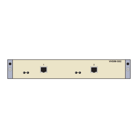
The VHSIM-G02 (Figure 1-1) has two ports that provide Gigabit Ethernet connections. There are two possible modes of operation for the VHSIM-G02. In mode one, both ports are active and transmit/receive data simultaneously. This mode can only be selected if the host platform has 16 or less fixed front panel ports. -
Page 18: Structure Of This Guide
Read through this manual completely to familiarize yourself with its content and to gain an understanding of the features and capabilities of the VHSIM-G02. The following list provides an overview of each section of this manual: Chapter 1, Introduction, outlines the contents of this manual, describes the VHSIM-G02 features and concludes with a web site address where related manuals can be obtained. -
Page 19: Connectivity
RELATED DOCUMENTATION The documentation for the host platform in which the VHSIM-G02 is to be installed, whether standalone device or module, provides additional information about the setup of the VHSIM-G02. This user’s guide references procedures in these documents, where appropriate, but does not repeat them. -
Page 20: Getting Help
A description of any action(s) already taken to resolve the problem (e.g., changing mode switches, rebooting the unit, etc.) • The serial and revision numbers of all involved Cabletron Systems products in the network • A description of your network environment (layout, cable type, etc.) •... -
Page 21: Chapter 2 Installation
They can damage the VHSIM-G02. Unpack the VHSIM-G02 as follows: 1. Remove the VHSIM-G02 from the shipping box. Leave the module in the antistatic bag until you are ready to install it. 2. Attach the antistatic wrist strap. Refer to the instructions on the antistatic wrist strap package. -
Page 22: Installing The Vhsim-G02
Chapter 2: Installation INSTALLING THE VHSIM-G02 You can install a VHSIM-G02 in any Cabletron Systems device that supports VHSIM technology (e.g., 2E253-49R, 6H252-17). Refer to the release notes for the version of firmware running NOTE on the Cabletron Systems device to ensure that the VHSIM-G02 is supported. - Page 23 Installing the VHSIM-G02 4. Lay the module down with the internal components facing up. 5. Refer to Figure 2-1 and remove the two faceplate mounting screws and the VHSIM coverplate. Save the screws. VHSIM Coverplate Faceplate Mounting Screws Host Platform...
- Page 24 Chapter 2: Installation 6. Refer to Figure 2-2 and position the VHSIM-G02 behind the module faceplate, above the connectors. Connectors Cutaway view of connectors VHSIM-G02 Faceplate Mounting Screws Figure 2-2 Installing the VHSIM-G02 in the Host Platform 7. Align the VHSIM-G02 connectors with the VHSIM connectors on the module.
-
Page 25: Installing The Vhsim-G02 In A Standalone Device
8. Press down firmly on the VHSIM-G02 until the connectors slide all the way onto the pins. Ensure that the standoffs on the interface module align with the standoff screw holes on the VHSIM-G02. 9. Secure the VHSIM-G02 to the module faceplate using the mounting screws saved in step 5. - Page 26 5. Refer back to Figure 2-1 and remove the two faceplate mounting screws and the VHSIM coverplate. Save the screws. 6. Refer back to Figure 2-2 and place the VHSIM-G02 module behind the standalone device faceplate. 7. Align the VHSIM-G02 connectors with the pins on the standalone device.
-
Page 27: Network Connections
1. Ensure that the device connected to the other end of the segment is powered ON. 2. Connect the twisted pair segment to the VHSIM-G02 by inserting the RJ45 connector on the twisted pair segment directly into the RJ45 port as shown in Figure 2-3. - Page 28 4. Repeat steps 1 through 3 above, for a second connection, as needed. 5. If a link cannot be established, refer to Chapter 3 for LED troubleshooting details. Contact Cabletron Systems if a problem persists. Refer to Getting Help in the Introduction.
-
Page 29: Lanview Leds
This chapter describes how to use the LANVIEW LEDs to monitor the VHSIM-G02 status and diagnose VHSIM-G02 problems. Figure 3-1 shows the location of the VHSIM-G02 LEDs. Refer to Table 3-1 for a description of the LEDs. Section 3.2 describes redundancy. -
Page 30: Redundancy
In the redundancy mode, one port is active while the other is redundant. In the redundancy mode, only one of the two ports on the VHSIM-G02 is active at one time. The port with link status showing (either a green LED, solid or blinking, or an amber LED) is the active port. -
Page 31: Chapter 4 Local Management
LOCAL MANAGEMENT This chapter provides information about using Local Management with the VHSIM-G02. The VHSIM-G02 is managed using the Local Management Ethernet screens for configuration and statistics on the host platform. The host platform is the interface module or standalone device NOTE in which the VHSIM-G02 is installed. - Page 32 Chapter 4: Local Management VHSIM-G02 User’s Guide...
-
Page 33: Vhsim-G02 Specifications
VHSIM-G02 SPECIFICATIONS This chapter lists the specifications and regulatory requirements for the VHSIM-G02. Cabletron Systems reserves the right to change these specifications at any time without notice. PHYSICAL AND ENVIRONMENTAL SPECIFICATIONS Table A-1 Physical Properties of the VHSIM-G02 Dimensions Weight... -
Page 34: Gigabit Port Pin Assignments
GIGABIT PORT PIN ASSIGNMENTS The following pin assignments are for the RJ45 Gigabit Ethernet ports on the VHSIM-G02. The twisted pair ports conform to the IEEE 802.3ab specification. The cables are 4-pair Category 5 UTP, up to 100 meters in length.
Need help?
Do you have a question about the VHSIM-G02 and is the answer not in the manual?
Questions and answers