Sign In
Upload
Download
Table of Contents
Contents
Add to my manuals
Delete from my manuals
Share
URL of this page:
HTML Link:
Bookmark this page
Add
Manual will be automatically added to "My Manuals"
Print this page
×
Bookmark added
×
Added to my manuals
Manuals
Brands
WAGO Manuals
Control Unit
750-555
Manual
WAGO 750-555 Manual
4-channel analog output module 4-20 ma for wago-i/o-system 750
Hide thumbs
1
2
3
4
5
6
7
8
9
10
11
12
13
14
15
16
17
18
19
20
21
22
23
24
25
26
27
28
29
30
31
32
33
34
35
36
37
38
39
40
41
42
43
44
45
46
page
of
46
Go
/
46
Contents
Table of Contents
Bookmarks
Table of Contents
Table of Contents
Figure 4: CAGE CLAMP
1 Notes about this Documentation
Validity of this Documentation
Copyright
Symbols
Number Notation
Font Conventions
Table 1: Number Notation
Table 2: Font Conventions
2 Important Notes
Legal Bases
Subject to Changes
Personnel Qualifications
Use of the WAGO-I/O-SYSTEM 750 in Compliance with Underlying Provisions
Technical Condition of Specified Devices
Disposal
Safety Advice (Precautions)
3 Device Description
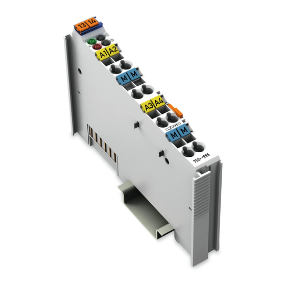
View
Figure 1: View
Table 3: Legend for Figure "View
Connectors
Data Contacts/Local Bus
Figure 2: Data Contacts
Power Jumper Contacts/Field Supply
Figure 3: Power Jumper Contacts
Table 4: Legend for Figure "Power Jumper Contacts
CAGE CLAMP ® Connectors
Table 5: Legend for Figure "CAGE CLAMP
Display Elements
Operating Elements
Figure 5: Display Elements
Table 6: Legend for Figure "Display Elements
Schematic Diagram
Figure 6: Schematic Diagram
Technical Data
Device Data
Power Supply
Communication
Outputs
Table 7: Technical Data - Device
Table 8: Technical Data - Power Supply
Table 9: Technical Data - Communication
Table 10: Technical Data - Outputs
Connection Type
Climatic Environmental Conditions
Table 11: Technical Data - Field Wiring
Table 12: Technical Data - Power Jumper Contacts
Table 13: Technical Data - Data Contacts
Table 14: Technical Data - Climatic Environmental Conditions
Approvals
Standards and Guidelines
4 Process Image
Table 15: Process Image
5 Mounting
Mounting Sequence
Inserting and Removing Devices
Inserting the I/O Module
Figure 7: Insert I/O Module (Example)
Figure 8: Snap the I/O Module into Place (Example)
Removing the I/O Module
Figure 9: Removing the I/O Module (Example)
6 Connect Devices
Connecting a Conductor to the CAGE CLAMP
Figure 10: Connecting a Conductor to a CAGE CLAMP
Connection Example
Figure 11: Connecting Diagram
7 Use in Hazardous Environments
Marking Configuration Examples
Marking for Europe According to ATEX and Iecex
Figure 12: Marking Example According to ATEX and Iecex
Figure 13: Text Detail - Marking Example According to ATEX and Iecex
Table 16: Description of Marking Example According to ATEX and Iecex
Figure 14: Marking Example for Approved Ex I I/O Module According to ATEX and Iecex
Figure 15: Text Detail - Marking Example for Approved Ex I I/O Module According to ATEX and Iecex
Table 17: Description of Marking Example for Approved Ex I I/O Module According to ATEX and Iecex
Marking for America (NEC) and Canada (CEC)
Figure 16: Marking Example According to NEC
Figure 17: Text Detail - Marking Example According to NEC 500
Table 18: Description of Marking Example According to NEC 500
Figure 18: Text Detail - Marking Example for Approved Ex I I/O Module According to NEC 505
Figure 19: Text Detail - Marking Example for Approved Ex I I/O Module According to NEC 506
Table 19: Description of Marking Example for Approved Ex I I/O Module According to NEC 505
Table 20: Description of Marking Example for Approved Ex I I/O Modules According to NEC 506
Figure 20: Text Detail - Marking Example for Approved Ex I I/O Modules
Table 21: Description of Marking Example for Approved Ex I I/O Modules
Installation Regulations
Special Notes Regarding Explosion Protection
Special Notes Regarding ANSI/ISA Ex
List of Figures
List of Tables
Advertisement
Quick Links
1
Display Elements
2
Schematic Diagram
3
Outputs
4
Technical Data
5
Process Image
6
Table 15: Process Image
Download this manual
Manual
WAGO-I/O-SYSTEM 750
750-555
4AO 4-20mA
4-Channel Analog Output Module 4-20 mA
Version 1.2.1
Table of
Contents
Previous
Page
Next
Page
1
2
3
4
5
Advertisement
Chapters
Table of Contents
3
List of Figures
44
Table of Contents
Need help?
Do you have a question about the 750-555 and is the answer not in the manual?
Ask a question
Questions and answers
Related Manuals for WAGO 750-555
Control Unit WAGO 750-559/040-000 Manual
4ao 0-10v dc /xtr 4-channel analog output module, 0-10 vdc /xtr for wago-i/o-system 750 xtr (52 pages)
Control Unit WAGO 750-557/040-000 Manual
4-channel analog output module, ±10 vdc /xtr for wago-i/o-system 750 xtr (52 pages)
Control Unit WAGO 750-597 Manual
8ao 0-10v/+-10v dc 8-channel analog output; 0...10 v/+-10 v for wago-i/o-system 750 (88 pages)
Control Unit WAGO 750-506 Series Manual
2do 24v dc 0.5a/ diagnostics, 2-channel digital output, 24 vdc, short-circuit, protected, high-side switching, with diagnostics (54 pages)
Control Unit WAGO WAGO-I/O-SYSTEM 750-508 Manual
2do 24v dc 2.0a, diagnostics, 2-channel digital output module dc 24 v, shortcircuit protected; high-side switching, with diagnostics (52 pages)
Control Unit WAGO 750-502 Manual
Fieldbus independent i/o modules, 2 do ac/dc 230 v ssr, 0.3 a for wago-i/o-system (12 pages)
Control Unit WAGO WAGO-I/O-SYSTEM 750 Manual
2-channel digital output module dc 24 v, shortcircuit protected, high-side switching. 2do 24v dc 2.0a (50 pages)
Control Unit WAGO 750 Series Manual
Fieldbus independent i/o modules. pulse width output module (26 pages)
Control Unit WAGO 750-564 Manual
4ao u/i 4-channel analog output module; voltage/current for wago-i/o-system 750 (102 pages)
Control Unit WAGO 750-535 Manual
2do 24v dc ex i, 2-channel digital output module 24 v dc, ex i for wago-i/o-system 750 (52 pages)
Control Unit WAGO 750-513 Series Manual
2do 230v ac 2.0a/ relay 2no/ potential free, 2-channel relay output module 230 vac, 30 vdc, isolated outputs; 2 make contacts for wago-i/o-system 750 series (52 pages)
Control Unit WAGO 750-536 Manual
8 do dc 24 v 0.5 a, negative switching, fieldbus independent i/o modules for wago-i/o-system 750 (12 pages)
Control Unit WAGO 750-509 Manual
2do 230v ac 0.3a/ssr, 2-channel digital output module 230 vac/dc, with solid state relay 0.3 a for wago-i/o-system 750 (50 pages)
Control Unit WAGO 750-538 Manual
2do relay ex i 2-channel relay output module, 100 vac, 30 vdc, ex i, isolated outputs, 2 changeover contacts for wago-i/o-system 750 (60 pages)
Control Unit WAGO 750-527 Manual
4do 30v ac/dc 2.0a ssr 4-channel digital output; 30 vac/dc, 2.0 a, solid-state for wago-i/o-system 750 series (52 pages)
Control Unit WAGO 750-528 Manual
4do 30v ac/dc 2.0a ssr isolated 4-channel digital output, 30 vac/dc, 2.0 a, solid-state, isolated for wago-i/o-system 750 series (50 pages)
This manual is also suitable for:
4ao 4-20ma
Table of Contents
Print
Rename the bookmark
Delete bookmark?
Delete from my manuals?
Login
Sign In
OR
Sign in with Facebook
Sign in with Google
Upload manual
Upload from disk
Upload from URL


Need help?
Do you have a question about the 750-555 and is the answer not in the manual?
Questions and answers