Table of Contents
Advertisement
Quick Links
BATTERY OPERATED
BATTERY OPERATED
PHOTOELECTRIC DETECTOR
PHOTOELECTRIC DETECTOR
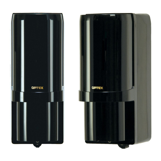
AX-100TFRi/AX-200TFRi
AX-100TFRi/AX-200TFRi
FEATURES
• UL Listed for Commercial/Residential applications,
and for c-UL Listed for Residential applications.
• Prewiring ; Battery operated photoelectric detector & wireless
transmitter
- You need to prepare just batteries, and easy to layout you
wireless system
• Battery-operated detector
Batteries are not included.
Use four LSH20 (3.6 V, 13 Ah) batteries manufactured by SAFT.
Battery life: AX-100TFRi Approximately five years
AX-200TFRi Approximately three years (transmitter)
Approximately five years (receiver)
• Back box for wireless transmitters
Back box can conceal two wireless transmitters and batteries.
• N.C./N.O. selection switch
Both N.C. and N.O. input wireless transmitters can be used.
• Battery saving function for wireless transmitter
Turning ON the battery saving timer switch reduces the battery
consumption of the wireless transmitter.
• Intermittent output function
Turning ON the intermittent output function, alarm signals are sent
periodically to avoid missed alarms while the beam is broken.
• 4 channel beam frequency selector
Crosstalk is eliminated with 4, channel selectable, beam
frequencies. Used when stacking beams or for long range
applications.
• International protection
IP55
• LED indicator for an easy alignment
It flickers on/off to help with easy alignment located on the receiver.
• D.Q. circuit (environmental disqualification)
The environmental compensation circuit is designed to eliminate
false alarms caused by snow, fog, heavy rain, ice and misalignment.
• Tamper
Form C output activates when either cover or back box or chassis
is removed.
• Beam interruption adjustment function
This function allows you to select the suitable beam interruption
time for any environment.
CONTENTS
1 INTRODUCTION
1-1 BEFORE YOUR OPERATION
2
3
4
5
5-2 OPERATION CHECK
6
7
7-1 TROUBLE SHOOTING
8
DIMENTIONS
9
9-1 SPECIFICATIONS
10
OPTIONS
AX-100 TFRi
AX-200 TFRi
1
INTRODUCTION
1-1 BEFORE YOUR OPERATION
ï Read this instruction manual carefully prior to installation.
ï After reading, store this manual carefully in an easily accessible
place for reference.
ï This manual uses the following warning indications for correct use
of the product, harm to you or other people and damage to your
assets, which are described below. Be sure to understand the
description before reading the rest of this manual.
Warning
Caution
This symbol indicates prohibition. The specific prohibited
action is provided in and/or around the figure.
This symbol requires an action or gives an instruction.
Do not use the product for purposes other than the detection
of moving objects such as people and vehicles.
Do not use the product to activate a shutter, etc., which may
cause an accident.
Do not touch the unit base or power terminals of the
product with a wet hand (do not touch when the product
is wet with rain, etc.). It may cause electric shock.
Never attempt to disassemble or repair the product. It may
cause fire or damage to the devices.
Do not use batteries other than those specified.
Specified batteries:
Four LSH20 batteries manufactured by SAFT
1
Do not use batteries that have different levels of power
2
remaining (i.e., new and used batteries).
2
Not observing the above may result in an explosion, leakage
of electrolyte, emission of toxic gases or other outcomes that
2
may be harmful to people and property.
2
[Handling of Batteries]
3
Fire, explosion and severe burn hazard. Do not recharge,
4
short circuit, crush, disassemble, heat above 100 C (212 F),
5
incinerate, or expose contents to water.
Do not solder directly to the cell.
7
7
8
Do not pour water over the product with a bucket, hose, etc.
8
The water may enter, which may cause damage to the
9
devices.
9
Clean and check the product periodically for safe use. If any
9
problem is found, do not attempt to use the product as it is
and have the product repaired by a professional engineer or
10
electrician.
10
10
10
10
10
12
12
-1-
UL
No. 59-2000-1 1308-30
INSTALLATION INSTRUCTIONS
consists of AX-100 TFR and EN 1941.
(30m/100ft. with 4 selectable beam frequencies
and INOVONICS' wireless transmitter)
consists of AX-200 TFR and EN 1941.
(60m/200ft. with 4 selectable beam frequencies
and INOVONICS' wireless transmitter)
Failure to follow the instructions provided with
this indication and improper handling may cause
death or serious injury.
Failure to follow the instructions provided with
this indication and improper handling may cause
injury and/or property damage.
Warning
Caution
No. 59-2000-1
Advertisement
Table of Contents


Need help?
Do you have a question about the AX-100 TFRi and is the answer not in the manual?
Questions and answers