Table of Contents
Advertisement
Quick Links
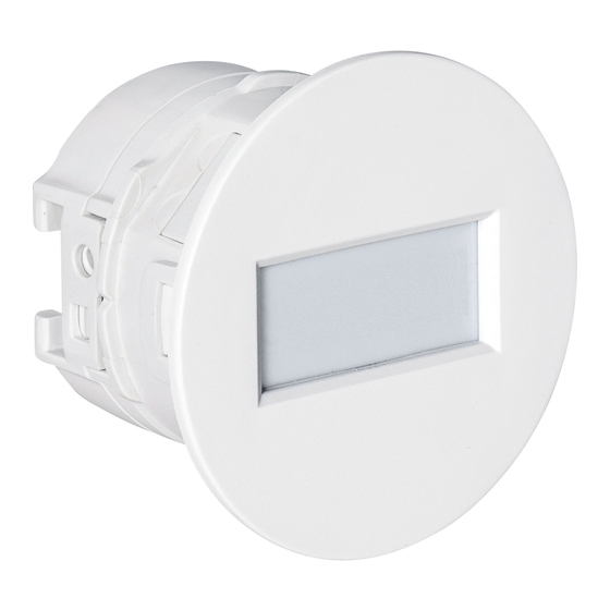
Indoor Recessed Mount PIR Detector
Indoor Recessed Mount PIR Detector
AP-20NB(C)
AP-20NB(C)
Curtain area/Wired model
<< Contents >>
Page
2
3
1
4
2
mount
5
3
8
9
10
10
11
12
6.0 m (20' ) curtain detection area
Ceiling/Wall
6
7
1
INSTALLATION INSTRUCTIONS
at 4.5 m (14' 9" ) mounting height
No.59-3223-0 2207-04
EN
Advertisement
Table of Contents

Related Manuals for Optex AP-20NB(C)


Summary of Contents for Optex AP-20NB(C)
-
Page 1: Table Of Contents
No.59-3223-0 2207-04 INSTALLATION INSTRUCTIONS Indoor Recessed Mount PIR Detector Indoor Recessed Mount PIR Detector AP-20NB(C) AP-20NB(C) Curtain area/Wired model 6.0 m (20’ ) curtain detection area at 4.5 m (14’ 9” ) mounting height << Contents >> Before installation Page - Manufacturer’... -
Page 2: Before Installation
Before installation - Manufacturer’ s statement Symbol Meaning Symbol Meaning Check mark indicates recommendation. Failure to follow the instructions provided with this indication Warning Nix sign indicates prohibition. and improper handling may cause death or serious injury. Failure to follow the instructions provided with this indication Special attention is required to the Caution NOTE... -
Page 3: Parts Identification
- Parts identifications Base cover Alarm output mode PIR sensitivity Tamper switch Top cover Lens Accessories Mounting Bezel for an 86-type box Retaining spring x 2 Fixing screw Screw cap x 2... -
Page 4: Settings
Settings Disassemble Open the base cover, and to set the detector. Jumper pin settings Alarm output mode PIR sensitivity Turn the jumper PIN by 90 degrees to prevent interference with the casing. N.C. (default) N.O. (recommended) (default) Mounting height: > 3.5 m 3.0 to 3.5 m <... -
Page 5: Installation
Installation 2-1. Ceiling/Wall mount without switch box Accessories Install a retaining spring on both sides. used in this installation (follow the illustrated arrow steps to complete the assembly of the retaining spring.) Retaining spring x 2 Make a ø45 mm (1.77”) hole in the ceiling for mounting. ø45 mm (1.77”) Insert the detector into the hole so that the retaining springs come first. -
Page 6: Mount
2-2. Ceiling/Wall mount with 86-type box Accessories used in this installation Prepare an 86-type box on the ceiling or back of the wall. Mounting Bezel for an 86-type box Screw cap x 2 Options to procure in the market 86-type box x 1 Screw x 2 NOTE Install the detector into the 86-type box. -
Page 7: Wiring
2-3. Wiring [1] Red Power supply: Positive [2] Black Power supply: Negative [3] White Alarm output [4] Yellow Alarm output [5] Green Tamper output [6] Blue Tamper output Power cable length The power cable should be limited to the following length. AP-20NB(C) WIRE GAUGE 12 V DC... -
Page 8: Checking
Checking 3-1. Walk test Power on. Wait for 60 seconds to complete the warm-up time. 60 sec. Power Walk in the detection area to check the detecting performance. Start operation. -
Page 9: Others
Others - Specifications Model AP-20NB(C) Detection method Passive infrared < Ceiling mount > < Wall mount > Detection area 6.0 m x 1.0 m (20’ x 3’3”) 6.0 m x 4.5 m (20’ x 14’9”) at 4.5 m (14’9”) height at 1.5 m (4’11”) height 2.5 m to 4.5 m 1.5 m (4’11”): Horizontal... -
Page 10: Dimensions
- Dimensions With 86-type box mount Without switch box mount 102 (4.02) 86 (3.39) Unit: mm (inch) - Detection area Ceiling mount Maximum detection area Mounting height (H) (8’ 2” ) (9’ 11” ) (11’ 6” ) (13’... -
Page 11: Troubleshooting
- Troubleshooting Problem Cause Solution Check the power supply of the detector. The power supply voltage does not meet the requirement Refer to “Specifications” on the page 9 for the power due to disconnection from the power supply or low voltage. supply voltage. -
Page 12: Compliance
OPTEX CO., LTD. (JAPAN) www.optex.net OPTEX INC./AMERICAS HQ (U.S.) OPTEX SECURITY SAS (France) OPTEX KOREA CO.,LTD. (Korea) www.optexamerica.com www.optex-europe.com/fr www.optexkorea.com OPTEX (EUROPE) LTD./EMEA HQ (U.K.) OPTEX SECURITY Sp.z o.o. (Poland) OPTEX (DONGGUAN) CO.,LTD. www.optex-europe.com www.optex-europe.com/pl SHANGHAI OFFICE (China) www.optexchina.com OPTEX SECURITY B.V.
Need help?
Do you have a question about the AP-20NB(C) and is the answer not in the manual?
Questions and answers