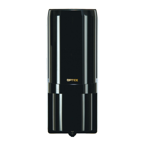
Optex AX-70TN Installation Manual
Photoelectric detector
Hide thumbs
Also See for AX-70TN:
- Installation instructions manual (14 pages) ,
- Installation manual (9 pages)
Table of Contents
Advertisement
PHOTOELECTRIC DETECTOR
AX-70TN, AX-130TN, AX-200TN
AX-100TF, AX-200TF
Features
< AX-70/130/200TN, AX-100/200TF >
• High-performance waterproof structure
• Horizontal alignment dial for user-friendliness
• Adjustable beam interruption period
• Tamper function
• Optional Accessories : Heating unit (HU-3), Back cover (BC-3),
• UL Listed
For Safe Use of the Product
・Read this instruction manual carefully prior to installation.
・After reading, store this manual carefully in an easily accessible place for reference.
・ This manual uses the following warning indications for correct use of the product and harm to you or other people and damage to
your assets, which are described below. Be sure to understand the description before reading the rest of this manual.
Failure to follow the instructions provided with this indication and improper handling may cause death or
WARNING
serious injury.
Failure to follow the instructions provided with this indication and improper handling may cause injury
CAUTION
and / or property damage.
This symbol indicates prohibition. The speci c prohibited action is provided in and/or around the guer.
This symbol requires an action or gives an instruction.
WARNING
CAUTION
1. PRECAUTIONS
2. PARTS IDENTIFICATION
3. INSTALLATION
3-1 NOTE
3-2 INSTALLATION METHOD
4. WIRE CONNECTION
5. ALIGNMENT
5-1 OPTICAL ALIGNMENT
5-2 BEAM INTERRUPTION TIME
5-3 4 SELECTABLE BEAM FREQUENCIES * TF ONLY
Pole side cover (PSC-3)
Do not use the product for purposes other than the detection of moving objects such as people and vehicles.
Do not use the product to activate a shutter, etc., which may cause an accident.
Do not touch the unit base or power terminals of the product with a wet hand (do not touch when the
product is wet with rain, etc.). It may cause electric shock.
Never attempt to disassemble or repair the product. It may cause re or damage to the devices.
Do not exceed the voltage or current rating speci ed for any of the terminals during installation, doing so
may cause re or damage to the devices.
Do not pour water over the product with a bucket, hose, etc. The water may enter, which may cause damage
to the devices.
Clean and check the product periodically for safe use. If any problem is found, do not attempt to use the
product as it is and have the product repaired by a professional engineer or electrician.
< STANDARD >
< 4 SELECTABLE BEAM FREQUENCIES >
< AX-100/200TF ONLY >
• 4 selectable beam frequencies
• LED indicator for ne beam alignment level
• D.Q. circuit (Environmental disquali cation)
• Alarm memory
C O N T E N T S
6. WALK TEST
7. SPECIAL FUNCTION * TF ONLY
7-1 ENVIRONMENTAL DISQUALIFICATION
7-2 ALARM MEMORY
8. OPTIONAL ACCESSORIES
8-1 HEATING UNIT : HU-3
8-2 BACK COVER : BC-3
8-3 POLE SIDE COVER : PSC-3
9. TROUBLE SHOOTING
10. SPECIFICATIONS
No. 59-1282-6 0808-20
INSTALLATION MANUAL
N219
Advertisement
Table of Contents

Summary of Contents for Optex AX-70TN
- Page 1 No. 59-1282-6 0808-20 INSTALLATION MANUAL PHOTOELECTRIC DETECTOR AX-70TN, AX-130TN, AX-200TN < STANDARD > N219 AX-100TF, AX-200TF < 4 SELECTABLE BEAM FREQUENCIES > Features < AX-70/130/200TN, AX-100/200TF > < AX-100/200TF ONLY > • High-performance waterproof structure • 4 selectable beam frequencies •...
- Page 2 2. Alignment angle 3. Pole mounting Distances between the Receiver and the Transmitter ・ Pole size should be 1 1/4”-1 7/8” (φ32-48mm). Horizontally Vertically ex) AX-70TN : 70ft.(20m) (Standard U.S. 1 1/4” or 1 1/2”pipe) about 2.0ft.(60cm) 2.3ft.-3.3ft. (0.7-1m) about 3.3ft. (1m) It is not recommendable to install the units in this way (or direction).
- Page 3 3. Wiring Use wires in compliance with the following conditions: Knockout 1) Wire diameter: φ4 - 7mm 2) When using any other wires than the above, seal the wiring port with a waterproof agent (silicon, etc.) to prevent water from coming in through the gap.
- Page 4 5. ALIGNMENT 5-1 OPTICAL ALIGNMENT The optical alignment is an important adjustment to increase reliability. In accordance with the procedure indicated in the items 1. and 2. in this chapter, make sure to align the monitor jack that monitor output nothing to attain the maximum level. 1.
- Page 5 《EXAMPLE》 1. Long distance protection 2. Double stacked long distance protection transmitter receiver receiver receiver transmitter transmitter transmitterA receiverA receiverB transmitterB transmitterC receiverC transmitter receiver receiver receiver transmitter transmitter Note More than double stacked apprication is not possible. 3. Perimeter protection 4.
- Page 6 7-2 ALARM MEMORY * TF ONLY This function is used to indicate which detector was activated with alarm memory LED while several detectors are installed in one site. For rst 5 minutes after the alarm output, the alarm memory indicator do not light up. Then the alarm memory indicator keep lighting up for 55 minutes.
- Page 7 8-2 BACK COVER : BC-3 1. Cutout of the knockout 2. Installation of mounting plate 3. Installation of the unit base and the back cover Mounting plate lock screws Back cover lock screw Unit Base (for main unit) (The same applies to Optional Back Cover the opposite side.)
- Page 8 Unit : inches (mm) < note > These units are designed to detect an intruder and activate OPTEX CO., LTD. (JAPAN) (ISO 9001 Certified by LRQA)(ISO 14001 Certified by JET) an alarm control panel. Being only a part of a complete...


Need help?
Do you have a question about the AX-70TN and is the answer not in the manual?
Questions and answers