Table of Contents
Advertisement
INSTALLATION
INSTRUCTIONS
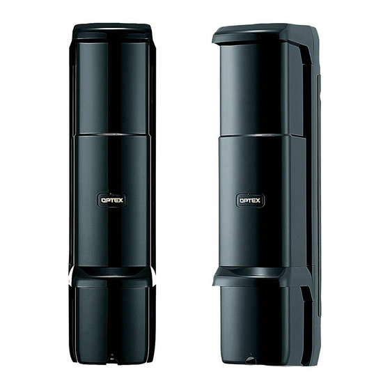
PHOTOELECTRIC DETECTOR
AX-350DH MK III
AX-650DH MK III
AX-350DH TS
AX-350DH BT
FEATURES
·Digital communication function
·Cross talk prevention function
·Peak Finder Interface (P.F.I ) of Dual Alignment
Level Indicator
·Mode-specific indicator allowing simple and
accurate optical alignment
·Simple beam alignment without the "Beam
Blocking Tool"
·Minimization of light disturbance
·ATPC ( Auto Transmit Power Control )
to optimize the power of beam
CONTENTS
11. HEATER UNIT HU-2
12. BACK COVER BC-1
Thank you for purchasing our product.Be sure to read the
following installation instructions carefully before beginning
installation.Make sure that the person in charge of system
management stores this manual carefully for maintenance
and management.
maximum detection range: 350ft.(100m)
maximum detection range: 650ft.(200m)
top/bottom unit AND/OR selectable
maximum detection range: 350ft.(100m)
model for beam tower, upper and lower unit unit AND/OR selectable
maximum detection range: 350ft.(100m)
·Multiple beam installation of up to 4 sets
·Simple optical alignment
·High waterproofing property; jet-proof : IP65
·Wide optical alignment range:
±90 degrees horizontally; ±20degrees vertically
*AX-350DH BT:
±60 degrees horizontally; ±45 degrees vertically
·Reduced possibility of false alarms caused by flying
objects
-1-
No.59-1073-0 0406-04
2
3
3
4
6
7
8
11
11
12
12
13
13
15
16
Advertisement
Table of Contents

Related Manuals for Optex AX-350DH BT


Summarization of Contents
INSTALLATION GOOD PRACTICE
Mount Unit on Solid Surface
Ensures stable mounting, preventing movement and potential beam obstruction.
Avoid Wind-Affected Obstructions
Prevents moving objects like plants or laundry from blocking the beam.
Prevent Direct Sunlight Entry
Avoids direct sunlight interfering with the detector's optical sensors.
Prevent Interference from Other Models
Ensures infrared beams from other detectors do not enter the receiver.
Avoid Aerial Wiring
Recommends clean wiring practices, avoiding exposed or aerial wires.
Ensure Solid Pole Footing
Requires mounting poles to have a stable and solid foundation.
Maintain Detection Range
Confirms mounting distance is within the specified detection range for optimal performance.
PARTS IDENTIFICATION
Transmitter Unit Components
Identifies key physical parts of the transmitter unit, including hood, base, and terminals.
Receiver Unit Components
Identifies key physical parts of the receiver unit, including hood, base, and terminals.
Transmitter Switch Functions
Explains the purpose and operation of switches on the transmitter, such as Address and Monitor.
Receiver Switch Functions
Details the switches on the receiver, including Master/Slave and Interruption Time settings.
NOTES ON INSTALLATION
Detection Range and Installation Height
Specifies recommended detection distances and installation heights for various models.
Alignment Angle Specifications
Defines the horizontal and vertical alignment angles for different detector models.
Pole Mounting Dimensions
Provides guidelines for pole diameter and wiring cable length for pole mounting.
WALL MOUNTING INSTALLATION
Removing Cover and Unit Base
Instructions for detaching the unit cover and base for installation.
Wiring Grommet Preparation
Guidance on preparing and fitting the wiring grommet for cable entry.
Mounting Plate Securing
Steps for securing the mounting plate to the wall using provided screws.
Unit Base Mounting and Wiring
Procedure for mounting the unit base and connecting terminals and beams.
Final Operation Check
Checks operations and attaching the cover after installation and alignment.
POLE MOUNTING INSTALLATION
Removing Cover and Unit Base
Instructions for detaching the unit cover and base for pole mounting.
U-Shaped Bracket Preparation
Guidance on preparing and attaching the U-shaped brackets for pole mounting.
Wiring Grommet and Wire Threading
Steps for preparing wiring grommets and threading wires through the unit.
Mounting Plate and Unit Base
Securing the mounting plate and mounting the unit base onto the pole.
Final Confirmation and Cover
Confirms operation and attaches the cover after pole installation.
WIRING
Wiring Examples
Illustrates wiring configurations for single-set and multi-level installations.
Wiring Distance Specifications
Provides tables for maximum wiring distances based on wire gauge and voltage.
OPTICAL ALIGNMENT
Aligning the Optical Axis
Explains the process of aligning the optical axis for optimal beam reception.
Master/Slave Selector Switch Setting
Details how to set Master/Slave switches to prevent cross-talk in multi-level installations.
AND/OR Selector Switch Setting
Describes the AND/OR switch settings for top/bottom level detection modes.
BEAM INTERRUPTION TIME ADJUSTMENT
Receiver Interruption Time Settings
Explains how to adjust interruption time using receiver switches for different detection speeds.
Bottom Level Interruption Time
Details the specific interruption time adjustment for the bottom level on TS/BT models.
RE-TRANSMISSION FUNCTION
Connection Method for Re-transmission
Guides on connecting external alarm outputs to the transmitter's alarm input.
WALK TEST
Walk Test Procedure
Outlines the steps for conducting a walk test to verify installation and alignment.
Alarm Condition Verification
Details checking the 'Alarm condition' LED status during the walk test.
HEATER UNIT HU-2 (Option)
Heater Unit HU-2 Feature
Describes the feature of the heater unit to prevent frost.
Heater Unit Mounting Method
Provides instructions for mounting the HU-2 heater unit.
Heater Unit Wiring Distance
Specifies wiring distance limits for the heater unit power supply.
BACK COVER BC-1 (Option)
Back Cover BC-1 Feature
Explains the feature of the back cover for tidier appearance.
Back Cover Installation
Details the steps for installing the BC-1 back cover.
DIMENSIONS
Dimensions for AX-350DH/AX-650DH/AX-350DH TS
Provides dimensional drawings and measurements for specific detector models.
Dimensions for AX-350DH BT
Displays dimensional drawings and measurements for the AX-350DH BT model.
Dimensions for Heater Unit HU-2
Shows dimensional drawings and measurements for the HU-2 heater unit.
TROUBLESHOOTING
Transmitter LED Issues
Addresses problems with transmitter LEDs not illuminating and their causes/solutions.
Receiver LED Issues
Covers problems with receiver LEDs not illuminating and their causes/solutions.
Alarm Condition LED Issues
Solves problems related to the 'Alarm condition' LED behavior.
False Alarm Causes and Solutions
Identifies causes of false alarms and provides corrective actions.
Indicator LED and Switch Issues
Addresses problems with indicator LEDs and AND/OR switching functionality.
SPECIFICATIONS
Photoelectric Detector Specifications
Lists detailed specifications for various photoelectric detector models.
Heater Unit HU-2 Specifications
Details the specifications for the optional Heater Unit HU-2.
Need help?
Do you have a question about the AX-350DH BT and is the answer not in the manual?
Questions and answers