Table of Contents
Advertisement
INSTALLATION
INSTRUCTIONS
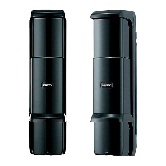
PHOTOELECTRIC DETECTOR
AX-350DH MK III
AX-650DH MK III
AX-350DH TS
AX-350DH BT
FEATURES
·Digital communication function
·Cross talk prevention function
·Peak Finder Interface (P.F.I ) of Dual Alignment
Level Indicator
·Mode-specific indicator allowing simple and
accurate optical alignment
·Simple beam alignment without the "Beam
Blocking Tool"
·Minimization of light disturbance
·ATPC ( Auto Transmit Power Control )
to optimize the power of beam
CONTENTS
11. HEATER UNIT HU-2
12. BACK COVER BC-1
Thank you for purchasing our product.Be sure to read the
following installation instructions carefully before beginning
installation.Make sure that the person in charge of system
management stores this manual carefully for maintenance
and management.
maximum detection range: 350ft.(100m)
maximum detection range: 650ft.(200m)
top/bottom unit AND/OR selectable
maximum detection range: 350ft.(100m)
model for beam tower, upper and lower unit unit AND/OR selectable
maximum detection range: 350ft.(100m)
·Multiple beam installation of up to 4 sets
·Simple optical alignment
·High waterproofing property; jet-proof : IP65
·Wide optical alignment range:
±90 degrees horizontally; ±20degrees vertically
*AX-350DH BT:
±60 degrees horizontally; ±45 degrees vertically
·Reduced possibility of false alarms caused by flying
objects
-1-
No.59-1073-0 0406-04
2
3
3
4
6
7
8
11
11
12
12
13
13
15
16
Advertisement
Table of Contents

Subscribe to Our Youtube Channel
Related Manuals for Optex AX-350DH MK III


Summary of Contents for Optex AX-350DH MK III
-
Page 1: Table Of Contents
INSTRUCTIONS installation.Make sure that the person in charge of system management stores this manual carefully for maintenance and management. PHOTOELECTRIC DETECTOR AX-350DH MK III maximum detection range: 350ft.(100m) AX-650DH MK III maximum detection range: 650ft.(200m) AX-350DH TS top/bottom unit AND/OR selectable maximum detection range: 350ft.(100m) -
Page 2: Wiring
[6] The mounting pole should have a [7] Ensure that the mounting distance solid footing. between the Transmitter and the Receiver (maximum detection range) is within the rating. 35-350ft. (10-100m): AX-350DH MK III AX-350DH TS AX-350DH BT 65-650ft.(20-200m) : AX-650DH MK III... -
Page 3: Parts Identification
Horizontally Vertically the Transmitter are listed below: 1.9inch(48mm). ·The length of the wiring cable out of 35-350ft.(10-100m) : AX-350DH MK III, AX-350DH TS, AX-350DH BT the pole should be within 23.5 65-650ft. (20-200m) : AX-650DH MK III inch(60cm). Normally, the installation height should 23.5 inch(60cm) -
Page 4: Installation Method
4. INSTALLATION METHOD When using the back cover BC-1 (optional), see 12. “BACK COVER BC-1” on Page13 4-1. Wall mounting [1] Removing the cover [2] Removing the unit base Loosen the cover lock screw and remove the cover. Loosen the four unit base mounting screws and remove the unit base by sliding it upward. - Page 5 4-2. Pole mounting [1] Removing the cover [2] Removing the unit base Loosen the cover lock screw and remove the cover. Loosen the four unit base mounting screws remove the unit base by Note sliding it upward. When removing the cover, The screws do not need to be do not put your finger on removed.
-
Page 6: Terminal Connections
Do not exceed the voltage or current rating specified for any of the terminals WARNING during installation, doing so may cause fire or damage to the devices. 5-1.AX-350DH MK III, AX-650DH MK III <Receiver> Transmitter < < < < <... - Page 7 6. WIRING 6-1. Wiring example 1-set installation Multi-level installation Connect the power supply in parallel. Connect the units serially for a Connect the power supply in parallel. normally closed alarm output and in parallel for a normally open output (the figure below shows an example for a normally closed alarm output). Provide the Transmitter/Receiver synchronization wiring and refer to 7- 2.
-
Page 8: Optical Alignment
7. OPTICAL ALIGNMENT 7-1. Aligning the optical axis ·Optical alignment is an important feature for maximizing the reliability of the product. Follow the instructions given in 7-2 to 7-5 in this chapter and make adjustment in such a way that the maximum voltage of the monitor jack is confirmed with the level indicator. - Page 9 7-3. Rough alignment by viewfinder While looking through the viewfinder on the left or right of the mirror, turn the dial to make alignment in such a way that the other detector is at the center of the sights. Vertical Alignment Dial Horizontal Alignment Dial Be sure to adjust both the upper and lower mirrors.
- Page 10 7-5. Fine adjustment with monitor jack Level of received light can be checked with voltmeter same as level indicator performs. [1] Preparing the voltmeter After the rough alignment using the viewfinder, make adjustment with the monitor jack for more accurate optical alignment.
-
Page 11: Beam Interruption Time Adjustment
8. BEAM INTERRUPTION TIME ADJUSTMENT This adjustment function allows you to match the sensitivity of the unit to its surroundings. Adjusting the interruption time determines the speed of objects detected by the detector. -When any large flying object to be disregarded such as a bird or a newspaper can occasionally interrupt the beam, set an appropriately long interruption time. -
Page 12: Heater Unit
10. WALK TEST Alarm condition Alarm condition Receiver Transmitter Be sure to conduct a walk test (to Make sure that the “Alarm condition” block the infrared beam) at the LED is OFF. If it is illuminated even If the “Alarm condition” LED is following three points: when the beams are not blocked, turned ON when the beam is... -
Page 13: Back Cover
12. BACK COVER BC-1 (Option) Feature Hides the pole and wiring on the rear of the detector for tidier appearance. See 4. “INSTALLATION METHOD” Break the knockout of the back Screw the back cover onto to mount the detector on the pole. cover with pliers, etc. -
Page 14: Dimensions
< AX-350DH BT > 3.6(91) 90° 3.03(77) 3.1(78) 120° 3.4(85) Dimensions:inch (mm) < HU-2 > 1.7(43) 0.06(1.5) Dimensions:inch (mm) -14-... -
Page 15: Troubleshooting
14. TROUBLESHOOTING Corrective Action Problem Possible Cause LEDs on the Transmitter are Check the voltage and make sure that it is between Inappropriate power voltage not illuminated. 10.5 and 30 VDC. Disconnection in power line Check the wiring. See 6-2 “Wiring distance between power supply Inappropriate wiring distance or wire diameter and detector”... -
Page 16: Specifications
15. SPECIFICATIONS < AX-350DH MK III, AX-650DH MK III, AX-350DH TS, AX-350DH BT > PHOTOELECTRIC DETECTOR Name AX-350DH MK III AX-650DH MK III AX-350DH TS AX-350DH BT Model 35 - 350ft. 65 - 650ft. 35 - 350ft. 35 - 350ft.
Need help?
Do you have a question about the AX-350DH MK III and is the answer not in the manual?
Questions and answers