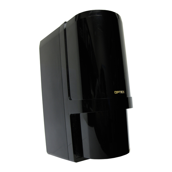
Optex AX-100TFR Installation Instructions Manual
Photoelectric detector
Hide thumbs
Also See for AX-100TFR:
- Basic configuration manual (16 pages) ,
- Frequently asked questions manual (15 pages) ,
- Installation instructions manual (16 pages)
Table of Contents
Advertisement
BATTERY OPERATED
BATTERY OPERATED
PHOTOELECTRIC DETECTOR
PHOTOELECTRIC DETECTOR
AX-100TFR/AX-200 TFR
AX-100TFR/AX-200 TFR
FEATURES
•AX-100TFR : Detection range: 30 m (100 ft.)
•AX-200TFR : Detection range: 60 m (200 ft.)
• Battery-operated detector
Batteries are not included.
Use four LSH20 (3.6 V, 13 Ah) batteries manufactured by SAFT.
Battery life: AX-100TFR Approximately five years
AX-200TFR Approximately three years (transmitter)
• Back box for wireless transmitters
Back box can conceal two wireless transmitters and batteries.
• N.C./N.O. selection switch
Both N.C. and N.O. input wireless transmitters can be used.
• Battery saving function for wireless transmitter
Turning ON the battery saving timer switch reduces the battery
consumption of the wireless transmitter.
• Intermittent output function
Turning ON the intermittent output function, alarm signals are sent
periodically to avoid missed alarms while the beam is broken.
• 4 channel beam frequency selector
Crosstalk is eliminated with 4, channel selectable, beam
frequencies. Used when stacking beams or for long range
applications.
• International protection
IP55
• LED indicator for an easy alignment
It flickers on/off to help with easy alignment located on the receiver.
• D.Q. circuit (environmental disqualification)
The environmental compensation circuit is designed to eliminate
false alarms caused by snow, fog, heavy rain, ice and misalignment.
• Tamper
Form C output activates when either cover or back box or chassis
is removed.
• Beam interruption adjustment function
This function allows you to select the suitable beam interruption
time for any environment.
CONTENTS
1
INTRODUCTION
1-1 BEFORE YOUR OPERATION
2
3
4
5
5-2 OPERATION CHECK
6
6-1 SPECIFICATIONS
No.59-1552-1 090403
INSTALLATION INSTRUCTIONS
N219
Approximately five years (receiver)
1
2
2
2
3
4
5
7
8
8
9
9
10
11
11
11
12
12
1
INTRODUCTION
1-1 BEFORE YOUR OPERATION
• Read this instruction manual carefully prior to installation.
• After reading, store this manual carefully in an easily accessible
place for reference.
• This manual uses the following warning indications for correct use
of the product, harm to you or other people and damage to your
assets, which are described below. Be sure to understand the
description before reading the rest of this manual.
Failure to follow the instructions provided with
Warning
this indication and improper handling may cause
death or serious injury.
Failure to follow the instructions provided with
Caution
this indication and improper handling may cause
injury and/or property damage.
This symbol indicates prohibition. The specific prohibited
action is provided in and/or around the figure.
This symbol requires an action or gives an instruction.
Do not use the product for purposes other than the detection
of moving objects such as people and vehicles.
Do not use the product to activate a shutter, etc., which may
cause an accident.
Do not touch the unit base or power terminals of the
product with a wet hand (do not touch when the product
is wet with rain, etc.). It may cause electric shock.
Never attempt to disassemble or repair the product. It may
cause fire or damage to the devices.
Do not use batteries other than those specified.
Specified batteries:
Four LSH20 batteries manufactured by SAFT
Do not use batteries that have different levels of power
remaining (i.e., new and used batteries).
Not observing the above may result in an explosion, leakage
of electrolyte, emission of toxic gases or other outcomes that
may be harmful to people and property.
[Handling of Batteries]
Fire, explosion and severe burn hazard. Do not recharge,
short circuit, crush, disassemble, heat above 100°C (212°F),
incinerate, or expose contents to water.
Do not solder directly to the cell.
Do not pour water over the product with a bucket, hose, etc.
The water may enter, which may cause damage to the
devices.
Clean and check the product periodically for safe use. If any
problem is found, do not attempt to use the product as it is
and have the product repaired by a professional engineer or
electrician.
-1-
Warning
Caution
Advertisement
Table of Contents

Related Manuals for Optex AX-100TFR


Summary of Contents for Optex AX-100TFR
-
Page 1: Table Of Contents
Warning this indication and improper handling may cause FEATURES death or serious injury. •AX-100TFR : Detection range: 30 m (100 ft.) Failure to follow the instructions provided with •AX-200TFR : Detection range: 60 m (200 ft.) Caution this indication and improper handling may cause •... -
Page 2: Precautions
Observe the prescribed The pole size should be 43 - transmitter-receiver distance 48 mm ( 1.69" - 1.89"). (range) and installation height. AX-100TFR PREPARATIONS Detection range: 30 m (100 ft.) AX-200TFR Detection range: 60 m (200 ft.) 2-1 ORDERING DETECTOR BATTERIES... -
Page 3: Installation
Insert the specified batteries into the back box. INSTALLATION 3-1 WALL MOUNTING Remove the chassis from the back box. Specified batteries SAFT LSH20 3.6 V 13 Ah Warning • Do not use batteries other than those specified. Specified batteries: Four LSH20 batteries manufactured by SAFT •... -
Page 4: Pole Mounting
3-2 POLE MOUNTING -Single set Remove the chassis from the back box. Take steps 3 through 6 refer to sec. “3-1” to install the wireless transmitters and batteries in the back box, and then install the back box on the chassis. Using a screwdriver or similar tool, break the knockout portion as shown. -
Page 5: Mounting In The Beam Tower
Fix the chassis on the pole. 3-3 MOUNTING IN THE BEAM TOWER Mounting inside optional beam tower. Detector 1 M4×30 screw (supplied) Detector 2 Remove the cover from the detector. Loosen the main unit fixing screw and remove the main unit from the back box. - Page 6 Fix the chassis and main unit mounting bracket (optional) in After completing the settings and operation check, insert the the tower. tamper bushing into each transmitter/receiver. Tamper bushing (option: MP-4) Caution • The switch selection is not recognized with the tamper bushing inserted.
-
Page 7: Wiring
3-4 WIRING -Using the N.C. type transmitter -Using the N.O. type transmitter This product is provided with wiring based on the assumption that When N.O. wireless transmitters are used, change the wiring and N.C. wireless transmitters are used. switch settings from initial setting. Connect the cables from the back box (Yellow/Yellow-white, Green/Green-white, and Black/Black-white) to the respective terminals on the wireless transmitters. -
Page 8: Setting
Receiver A the wired photoelectric detector, it could be a factor of false alarm. • In case that you install the battery operated photoelectric detector with Optex hard-wired photoelectric detector at the same site, ensure that Transmitter B Receiver B... -
Page 9: Optical Alignment
4-3 OPTICAL ALIGNMENT Adjust the horizontal and vertical angles while checking the light receiving status by Alarm indicator LED on the pairing receiver. Horizontal alignment angle Vertical alignment angle Low battery LED Alarm indicator LED 5° 5° Light 90° 90° Light received interrupted ON (Red) Fast flicker Slow flicker... -
Page 10: Adjusting Output
4-5 ADJUSTING OUTPUT -Setting the D.Q. output (environmental disqualification) D.Q. will send a trouble signal when the beam strength is below -Setting the battery saving timer acceptable levels, for more than 20 seconds, due to rain, snow, or heavy fog. Alarm output activation are limited by a timer 2 minutes. -
Page 11: Operation Check
5-3 TROUBLE SHOOTING OPERATION CHECK If the alarm indicator LED is OFF or flickering even though the beam is being interrupted, do the following: 5-1 LED INDICATION Align the optical axis again. Receiver Transmitter In a multi-detector configuration, the receiver may be receiving the infrared beam from an unrelated transmitter. -
Page 12: Specifications
** The transmitter is also equipped with AX100/200 TFR (BE). These products conform to the EMC Directive 2004/108/EC. OPTEX CO., LTD. (JAPAN) OPTEX INCORPORATED (USA) OPTEX SECURITY Sp.z o.o. (POLAND) TEL: +1-909-993-5770 TEL: +48-22-598-06-55 (ISO 9001 Certified) Tech: (800)966-7839 URL: http://www.optex.com.pl...
Need help?
Do you have a question about the AX-100TFR and is the answer not in the manual?
Questions and answers