
Subscribe to Our Youtube Channel
Related Manuals for Mitsubishi Electric MELFA BFP-A3614


Summary of Contents for Mitsubishi Electric MELFA BFP-A3614
- Page 1 Mitsubishi Industrial Robot Robot Seminar Textbook <Force Sensor Application> BFP-A3614...
- Page 3 MELFA Robot Seminar Curriculum <Force Sensor Application> Day 1 Day 2 Item Time Item Time Opening greetings 7) Force sense function (teaching) Orientation Practice (actual machine operation) Features of the force sensor 1) Specifications and configuration of the force sensor Force sensor specifications Selecting the force sensor set 90 min...
- Page 4 Safety Precautions Always read the following precautions and the separate "Safety Manual" before starting use of the robot to learn the required measures to be taken. CAUTION All teaching work must be carried out by an operator who has received special training.
- Page 5 The points of the precautions given in the separate "Safety Manual" are given below. Refer to the actual "Safety Manual" for details. DANGER When automatic operation of the robot is performed using multiple control devices (GOT, programmable controller, push-button switch), the interlocking of operation rights of the devices, etc.
- Page 6 CAUTION Make sure that if the safety fence entrance door is opened during automatic operation, the door is locked or that the robot will automatically stop. Failure to do so could lead to personal injuries. CAUTION Never carry out modifications based on personal judgments, non-designated maintenance parts.
- Page 7 CAUTION Make sure there are no mistakes in the wiring. Connecting differently to the way specified in the manual can result in errors, such as the emergency stop not being released. In order to prevent errors occurring, please be sure to check that all functions (such as the teaching box emergency stop, customer emergency stop, and door switch) are working properly after the wiring setup is completed.
- Page 8 Revision History Instruction Print Date Revision content Manual No. · 2018-07-31 BFP-A3614 First print...
-
Page 9: Table Of Contents
Introduction ................................... 1 1. What is the Force Sense Function? ........................1 2. Features of the force sense function ........................1 3. Main applications ..............................1 4. Procedure from selection to automatic operation ....................2 Chapter 1 Force Sensor Specifications and Configuration ....................3 1.1 Force Sensor Specifications .......................... - Page 10 (4) Specifying the force control mode (P_FsMod0/P_FsMod1, FSFMD0#) ............55 (5) Specifying the stiffness coefficient (P_FsStf0/P_FsStf1, FSSTF0#) ..............58 (6) Specifying the damping coefficient (P_FsDmp0/P_FsDmp, FSDMP0#) ............61 (7) Specifying the force command value and limit value (P_FsFCd0/P_FsFCd, FSFCMD0#) ....... 62 (8) Specifying the force sense control gain (P_FsGn0/P_FsGn1, FSSWF0#) ............
- Page 11 Appendix 4.2 Force Control Operation ........................162 (1) Checking the force sensor data communication ....................162 (2) Offset Cancel Operation ...........................163 (3) Selecting the Control Mode/Control characteristics ..................164 (4) Force Sense Control Enable/Disable Selection ....................164 (5) Force Sense Monitor ............................165 (6) Position search ..............................165 (7) Contact Detection .............................166 Appendix 5 Force Sense Log File ..........................167 Appendix 5.1 Force Sense Log File FTP Transfer ....................167...
-
Page 12: Introduction
Introduction 1. What is the Force Sense Function? The force sense function uses force sensor information with 6 degrees of freedom to provide the robot with a sense of its own force. Using dedicated commands and status variables compatible with the robot program language (MELFA-BASIC) facilitates work requiring micro force adjustments and power detection. -
Page 13: Procedure From Selection To Automatic Operation
4. Procedure from selection to automatic operation Step Description Reference Select the Force Sensor Chapter 1 Force Sensor Specifications and Configuration 1.3 Selecting the Force Sensor Set Attach the force sensor attachment Chapter 2 Installing the Force Sensor adapter 2.1 Attaching the Sensor Attachment Adapter Install the force sensor Chapter 2 Installing the Force Sensor 2.2 Install the Force Sensor... -
Page 14: Chapter 1 Force Sensor Specifications And Configuration
Chapter 1 Force Sensor Specifications and Configuration 1.1 Force Sensor Specifications There are two types (rated load: 200 N and 1000 N) of force sensors. (1) Specifications of the force sensor Item Unit Specification Value Remarks Model 1F-FS001-W200 1F-FS001-W1000 Fx, Fy, Fz Be sure to set the 1000 value within the rated... -
Page 15: Force Sensor External Dimensions
(2) Force Sensor External Dimensions Outline drawings of the force sensor are shown below. a) 1F-FS001-W200 Tap hole for attachment 4-M6×1.0 Sensor detection center Low head bolt for mounting sensor 4-M6×1.0... - Page 16 b) 1F-FS001-W1000 H7 effective depth 4 H7 effective Pin hole for positioning Pin hole for positioning depth 4 (Detection axis Y) ∅ ∅ (Detection axis X) connector Tool mounting surface Attachment adapter mounting surface Tap hole for attachment 4-M6×1.0 (Detection Sensor detection center axis Z) Low head bolt for mounting sensor 4-M6×1.0...
-
Page 17: Sensor Attachment Adapter External Dimensions
(3) Sensor Attachment Adapter External Dimensions Outline drawings of the sensor attachment adapter are shown below. a) For 1F-FS001-W200 (RV-2/4/7FR and RV-2/4/7F) 4 – M3 screw depth 6 4 – M6 screw through-hole 4 – 5.5 cut, ∅10 through-hole depth 10 (at equidistant points depth 6 (at equidistant points... - Page 18 c) For 1F-FS001-W1000 (RV-13/20FR and RV-13/20F) 4 – M6 screw through-hole, bottom hole 4.9 (at equidistant points on circumference) 4 – M3 screw depth 6, bottom hole depth 11 4 – 7 cut, ∅11 through-hole depth 8 (at equidistant points on circumference) depth 5 depth 6 Section A-A...
-
Page 19: Configuration Of The Force Sensor Set
(4) Configuration of the force sensor set Force sensor Force sense · The force sensor set for the FR series and F series (for interface unit model 200 N and 1000 N each) are available. For FR series 2F-DQ561 · The force sense interface units of the force sensor set For F series 2F-TZ561... -
Page 20: System Configuration
1.2 System Configuration The device configuration required to use the force sense function is shown below. a) FR Series Force sense interface unit (2F-DQ561) Serial cable between unit and sensor (2F-FSCBL1-05) 24 VDC output cable (2F-PWRCBL-01) Force sensor (1F-FS001-W200/1F-FS001-W1000) SSCNETIII cable 24 VDC power supply... - Page 21 b) F Series Force sense interface unit (2F-TZ561) Serial cable between unit and sensor (2F-FSCBL1-05) 24 VDC output cable (2F-PWRCBL-01) Force sensor SSCNETIII cable 24 VDC power supply (2F-PWR-01) Robot controller 24 VDC input power supply cable (2F-PWRCBL-02) Machine cable (Force sensor Robot attachment example)
-
Page 22: Selecting The Force Sensor Set
1.3 Selecting the Force Sensor Set This section describes the selection flow for the force sensor. Confirm the selection result and check "1.1 Force Sensor Specifications" to decide the force sensor to be used. (Refer to the next page for the first selection table.) (1) Selection flow Start... -
Page 23: First Selection Table
(2) First selection table FR Series Robot Application RV-FR Series RH-FR Series RV-2FR RV-4FR RV-7FR RV-13FR RV-20FR RH-3FR RH-6FR RH-12FR RH-20FR Close tolerance fit 4F-FS002H-W1000 Phase focusing 4F-FS002H-W200 4F-FS002H-W200 4F-FS002H-W200 Parts assembly (Upward and Test (Press/withdraw) downward limited) Inset Deburr/Polishing 4F-FS002H-W1000 4F-FS002H-W1000 F Series... -
Page 24: Moment By The Hand Shape And Posture Change
(3) Moment by the hand shape and posture change a) When the center of gravity position of the hand is out of the force sensor center Hand weight W1 (kg) Center of gravity of the hand Center of gravity of the Workpiece Depending on the hand shape, the moment is applied when the hand weight or force... - Page 25 b) When the center of gravity position of the hand is at the force sensor center Moment is applied by the hand weight when the posture changes. Center of gravity of hand Workpiece W (kg) Hand weight W (kg) Center of gravity of the Workpiece Moment around force sensor coordinate origin (Nm):...
-
Page 26: Chapter 2 Attaching The Force Sensor
Chapter 2 Attaching the Force Sensor A dedicated "sensor attachment adapter" is required to fix the force sensor to the robot. Attach the sensor attachment adapter to the robot mechanical interface before installing the force sensor. After installing the force sensor, it is necessary to define the relation between the force sensor coordinate system and robot coordinate system in the parameter setting. -
Page 27: Install The Force Sensor
2.2 Install the Force Sensor After attaching the sensor attachment adapter, install the force sensor. (1) Installing direction Install the force sensor so that the force sensor cable comes out from the lower right as the following picture shows when viewed from the robot front. View from the robot front Force sensor Force sensor cable... -
Page 28: Checking The Force Sensor Installation Condition
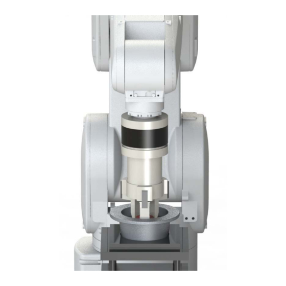
(3) Checking the force sensor installation condition The following figure shows the sensor attachment adapter and force sensor after the installation. Force sensor Sensor attachment adapter Force sensor cable 2.3 Fixing the force sensor cable Fix the force sensor cable to the force sensor attachment adapter. 1) Mount a cable tie fixture (attachment) on the sensor attachment adapter with cable tie fixation screw (attachment). -
Page 29: Relation Between Parameter Installation Position And Angle (Fsxtl)
2.4 Relation Between Parameter Installation Position and Angle (FSXTL) (1) Installation position For the installation position (FSXTL), set the position relation of the force sensor coordinate system from the mechanical interface coordinate system of the robot in the force sensor parameter setting. When using 1.1 (3) Sensor Attachment Adapter External Dimensions, the installation position is as... -
Page 30: Installation Angle
(2) Installation angle For the installation angle (FSXTL), set the rotation angle of the force sensor coordinate system for the mechanical interface coordinate system in the force sensor parameter setting. When installing in the direction described in "2.2 Install the Force Sensor", the installation angle is as follows. -
Page 31: Tool Installation
2.5 Tool installation Install the hand to the tool side of the force sensor. Select the bolt whose specifications are described below and tighten it little by little so that installation surfaces contact evenly. Nominal Tightening Engagement Force sensor model diameter torque [Nm] allowance [mm]... -
Page 32: Chapter 3 Device Connection And Wiring
Chapter 3 Device Connection and Wiring 3.1 Force Sense Interface Unit ⇔ Robot Controller Connect the force interface unit and robot controller. (1) FR series (a) CR800-D controller CR800-D controller (front) -21-... - Page 33 (b) CR800-R controller CPU module CN1 connector III cable SSCNET CR800-R controller (front) To OPT1 connector -22-...
-
Page 34: F Series
(2) F series (a) CR750-D controller -23-... - Page 35 (b) CR751-D controller -24-...
- Page 36 (c) CR750-Q/CR751-Q controller CPU module -25-...
-
Page 37: Force Sense Interface Unit ⇔ Force Sensor
3.2 Force Sense Interface Unit ⇔ Force Sensor Connect the force sense interface unit and force sensor. The cable for the RV-2FR and RV-2F is wired outside the robot (figure below). Standard robot + wire externally (external wiring) The adapter cable is not used for the standard robot. -
Page 38: Chapter 4 Parameter Setting
Chapter 4 Parameter Setting The correlation of the force sensor coordinate system and robot coordinate system needs to be defined in the parameter setting. After turning ON the power, set the parameters with RT ToolBox3. After setting the parameters, restart the controller. The setting value will be reflected by restarting. 4.1 Force Sensor Parameter Setting In the parameter setting window of RT ToolBox3, set the force sensor parameter, control mode, and control characteristics. -
Page 39: Force Control Mode
(2) Force control mode Force Control Mode parameter setting window 1) Force control mode 2) Coordinate system of force sense control 3) Control mode of 4) Stiffness coefficients 5) Damping coefficient axes Setting example Item Setting value Description Control mode Control mode1 Tool Coordinate Specify the force control coordinate... -
Page 40: Force Control Characteristics
Force control characteristics Force Control Characteristics parameter setting window 1) Control characteristics 4) Force detection setting value Tab switch 2) Force sense 3) Force control gain command value 5) Mode switch judgment value 6) Speed command value Setting example Setting Item Description value... -
Page 41: Hand Parameter Setting
4.2 Hand Parameter Setting Set the parameters for the weight, size, and center of gravity position of the hand in the parameter setting window of RT ToolBox3. For the size, input the total size of the actual hand, force sensor, and attachment adapter. Input the maximum size in X, Y, or Z direction, not the specific value. -
Page 42: Connection And Setting Check
4.3 Connection and Setting Check Before using the force sense function, check that the force sensor data is set in the correct coordinate system. (1) Checking the coordinate system Push the tip of the tool in any direction by finger to check that the robot follows it. 1) Enable the offset cancel with the teaching box. - Page 43 a) Enable offset cancel →select control mode and control characteristics → turn ON servo → force sense function enabled Description of the operation Step How to operate T/B screen method <Menu screen> Push the [6] key ("ENHANCED") in the <MENU> screen to display the <ENHANCED>...
- Page 44 Description of the operation Step How to operate T/B screen method <Force screen> Press the [SERVO] button to turn ON the servo. (The control mode is set to "1", and control feature to "1" as an example.) <Force screen> Press the [F1] key in the <FORCE>...
-
Page 45: Display The Force Sensor Data (Force Sense Monitor)
(2) Display the force sensor data (force sense monitor) The current value of the force sensor can be displayed on the force screen of the teaching box. The coordinate system for the displayed sensor data is based on the force sensor coordinate ... -
Page 46: Details Of Force Sensor Parameter
4.4 Details of Force Sensor Parameter Force sensor parameter list Parameter No. of Factory Default Parameter Description Name Elements Setting Force sense AXJNO Assigns the force sense interface unit 0, 0, 0, 0, 0, 0, interface unit integers connection. 0, 0, 0, 0, 0, 0, recognition 0, 0, 0, 0 Refer to:... -
Page 47: Robot Number (Axmeno), Axis Number (Axjno)
(1) Robot number (AXMENO), axis number (AXJNO) It is necessary to set parameters at the robot controller side in order for the robot controller to recognize the force sense interface unit. Set these parameters as follows. (The same parameters as that for the additional axis function are used.) Parameter No. -
Page 48: Calibration
(2) Calibration To use the force sense function, it is necessary to define (calibrate) the correlation between the force sensor coordinate system and force sense coordinate system (mechanical interface). Calibration is performed with the following parameter settings. There is a danger that the robot may move in an unintended direction if the calibration settings are incorrect. - Page 49 c) Coordinate system definition (mechanical interface) The force sense coordinate system (mechanical interface) is defined as follows. Force sense coordinate Mechanical interface system coordinate system (mechanical interface) For the force sense coordinate system (mechanical interface), the positive direction is the one in which the opposite force is applied when the robot moves to the positive direction in the mechanical interface coordinate system.
- Page 50 d) Parameter setting example 1) Parameter Setting Example 1 (for Recommended Installation) When the force sensor is installed in the recommended installation (See below) the parameter settings for elements 1 to 4 for FSHAND and FSXTL will be the default factory settings. Change only elements 1 to 3 for FSXTL.
- Page 51 2) Parameter Setting Example 2 (offset installation) If, as shown below, the force sensor coordinate system origin is offset 50 mm in the +Zm direction and rotated 30 degrees around the Zm-axis as viewed from the mechanical interface coordinate system, set the parameters as follows. Mechanical interface coordinate system Force sense coordinate system...
-
Page 52: Maximum Offset Value (Fscormx)
(3) Maximum offset value (FSCORMX) This parameter sets the position command offset upper limit for force sense control. If the offset exceeds this upper limit, an error (H2760) occurs. This acts as a protection function for inadequate operation or setting, and therefore the required minimum value should be set. Parameter No. -
Page 53: Filter Time Constant (Fsflctl)
(5) Filter time constant (FSFLCTL) The force sensor data filter time constant can be changed. When the sensor data is not stable or the robot vibrates during the force control, increasing the constant solves the problem. Increase the setting value···Decreases the vibration. However, because the sensor data delays, the sensitivity of the force sense detection and force sense control are lowered and the robot cannot react to micro force. -
Page 54: Chapter 5 Force Sense Function (Programming)
Chapter 5 Force Sense Function (Programming) Force sense function list This chapter describes the robot programming using the force sense function. The force sense function consists of "force sense control", "force sense detection", and "force sense log" functions. Function Class Function Overview Force Force control... -
Page 55: What Is Force Sense Control
5.1 What is Force Sense Control? The force sense control function is used to control robot flexibility and push force. Depending on the application, this function switches between "force control" and "stiffness control". 1) Force control This control mode controls the robot while pushing with a specified force. The robot moves automatically to the position at which the specified reactive force applies. -
Page 56: Enable/Disable The Force Sense Control
5.2 Enable/Disable the Force Sense Control Enable the force sense control when using the force sense control function of the force sensor, and disable the force sense control when ending the force sense control function of the force sensor. (1) Force sense control enable/disable command (FscOn/FscOff) with a program Start the force sense control based on the condition settings specified in the argument "Control mode", "Control feature"... -
Page 57: Force Sense Control Enable/Disable Selection With The Teaching Box
(2) Force sense control enable/disable selection with the teaching box The following describes how to enable/disable the force sense control with the teaching box. If performing JOG operation using force sense control, select "Enable", and if performing normal JOG operation, select "Disable". The enable/disable selection is common to both automatic operation and JOG operation. -
Page 58: Condition Groups And Condition Numbers
5.3 Condition Groups and Condition Numbers (1) Setting method All parameter settings are classified by "condition groups" consisting of the control mode and control characteristics, and "condition numbers." -1 to 9. When specifying conditions with the Fsc On command, they are specified with a combination of these "condition groups" and "condition numbers." Each parameter can be set by setting in the program (set as status variable) or setting in the parameter settings. -
Page 59: Setting Example
(2) Setting example a) Setting in the program (set as status variable) The following describes how to set the setting value to the program as status variable. Condition numbers "-1" and "0" can be used. '[Control mode (0)] P_FsStf0 = (+0.00,+0.00,+0.00,+0.00,+0.00,+0.00)(0,0) 'Stiffness coefficient [N/mm] P_FsDmp0 = (+0.00,+0.00,+0.00,+0.00,+0.00,+0.00)(0,0) 'Damping coefficient P_FsMod0 = (+1.00,+1.00,+1.00,+0.00,+0.00,+0.00)(0,0) - Page 60 b) Setting by the parameter Set conditions to the parameters by RT ToolBox3. Condition number "1" to "9" can be used. RT ToolBox3 parameter setting window Control mode Condition number 1 to 9 (example: 9) Control Condition number 1 to 9 (example: 4) characteristics Program example •...
-
Page 61: Selecting Control Mode And Control Feature In Teaching Box
(3) Selecting control mode and control feature in teaching box Before enabling force sense control, it is necessary to set the force sense control "control mode" and "control feature" beforehand. [Control mode/ Control feature selection operation] Specify the used "control mode" and "control feature" number. ... -
Page 62: Control Mode And Control Characteristics Details
5.4 Control Mode and Control Characteristics Details (1) Settings for the force sense control conditions When enabling force sense control, it is necessary to specify conditions for starting force sense control. Register these conditions by using the parameters and status variables. Up to 11 types of settings can be registered for each setting item. - Page 63 b) Control characteri stics Setting Item Description Reference Force command Sets the force command for force control (force priority mode). (5) Specifying the value force command The robot pushes with the specified force. value and limit Limit value Sets the limit value for the limited stiffness control. value Controls the robot’s force within the setting value.
-
Page 64: Control Mode And Control Characteristics Setting Compatibility Table
(2) Control mode and control characteristics setting compatibility table The following is the compatibility table for the setting item of the control mode and control characteristics when using the force control mode (position control, force control, stiffness control). Position control···Maintains the position and posture. Force control···Continuously applies the specified force to the specified axis direction. -
Page 65: Specifying The Force Sense Control Coordinate System (M_Fscod0/M_Fscod1, Fscod0#)
(3) Specifying the force sense control coordinate system (M_FsCod0/M_FsCod1, FSCOD0#) Specify the coordinate system controlling with the force sensor. M_FsCod0 / M_FsCod1 = 0 or 1 0: Tool coordinate system 1: XYZ coordinate system Program example Set the force sense control M_FsCod0=0 coordinate system to "Tool coordinate system". -
Page 66: Specifying The Force Control Mode (P_Fsmod0/P_Fsmod1, Fsfmd0#)
(4) Specifying the force control mode (P_FsMod0/P_FsMod1, FSFMD0#) Set the control mode for X, Y, Z, A, B, and C-axis each. P_FsMod0 / P_FsMod1 = (△ , △ , △ , △ , △ , △ ,0,0)(0,0) = 0 or 1 or 2 or 3 △... - Page 67 Practice 1: Specifying the force coordinate system 1) Execute program "1" to check the movement. 2) Create program "1" with RT ToolBox3 and write it to the robot. 3) When the writing is completed, close the program. Open the program again, and check that the 8th line is "M_FsCod0=0"...
- Page 68 Program "1" 1 '---------------------------------------------------------------------------- 2 ' Practice 1 Selecting force sense control coordinate system and specifying force control mode 3 '---------------------------------------------------------------------------- 4 '[Control mode (0)] 5 P_FsStf0 = (+0.00,+0.00,+0.00,+0.00,+0.00,+0.00)(0,0) 'Stiffness coefficient [N/mm] 6 P_FsDmp0 = (+0.00,+0.00,+0.00,+0.00,+0.00,+0.00)(0,0) 'Damping coefficient 7 P_FsMod0 = (+1.00,+1.00,+1.00,+0.00,+0.00,+0.00)(0,0) 'Force control mode (XYZ-axis enabled) 8 M_FsCod0 = 0...
-
Page 69: Specifying The Stiffness Coefficient (P_Fsstf0/P_Fsstf1, Fsstf0#)
(5) Specifying the stiffness coefficient (P_FsStf0/P_FsStf1, FSSTF0#) Stiffness control/limited stiffness control softness is specified with the stiffness coefficient. Set the stiffness coefficient for X, Y, Z, A, B, and C-axis each. The stiffness coefficient is equivalent to the spring constant. The stiffness of the control increases as the value increases, and decreases the control as the value decreases. - Page 70 Practice 2: Specifying the stiffness coefficient 1) Execute program "2" to check the movement. 2) Create program "2" with RT ToolBox3 and write it to the robot. 3) When the writing is completed, close the program. Open the program again, and check that the 8th line is "M_FsCod0=0"...
- Page 71 Program "2" 1 '---------------------------------------------- 2 ' Practice 2: Specifying the stiffness coefficient 3 '---------------------------------------------- 4 '[Control mode (0)] 5 P_FsStf0 = (+0.10,+0.10,+0.10,+0.00,+0.00,+0.00)(0,0) 'Stiffness coefficient [N/mm] 6 P_FsDmp0 = (+0.00,+0.00,+0.00,+0.00,+0.00,+0.00)(0,0) 'Damping coefficient 7 P_FsMod0 = (+2.00,+2.00,+2.00,+0.00,+0.00,+0.00)(0,0) 'Stiffness control mode (XYZ-axis enabled) 8 M_FsCod0 = 0 'Force sense control coordinate system (tool) 9 '[Control characteristics (0)]...
-
Page 72: Specifying The Damping Coefficient (P_Fsdmp0/P_Fsdmp, Fsdmp0#)
(6) Specifying the damping coefficient (P_FsDmp0/P_FsDmp, FSDMP0#) Set the damping coefficient when the robot vibrates at hand and workpiece contact, or when setting the response of the axis to which the force control and stiffness control are selected. P_FsDmp0 / P_FsDmp1 = (△ , △ , △ , △ , △ , △ ,0,0)(0,0) = 0.0 to 1.0 △... -
Page 73: Specifying The Force Command Value And Limit Value (P_Fsfcd0/P_Fsfcd, Fsfcmd0#)
(7) Specifying the force command value and limit value (P_FsFCd0/P_FsFCd, FSFCMD0#) a) Force command value Set the force command value for force control (force priority mode). Set the force command value for each specified axis. When force control is enabled, the robot moves so that the reactive force specified with the force command value can be obtained. -
Page 74: Specifying The Force Sense Control Gain (P_Fsgn0/P_Fsgn1, Fsswf0#)
(8) Specifying the force sense control gain (P_FsGn0/P_FsGn1, FSSWF0#) Adjust the response of the force sense control. When using the force control and stiffness control, this setting is required. The response improves as the setting value increases. If the setting value is too high, the operation may be unstable and increase the possibility of vibration due to high sensitivity at contact. - Page 75 <<MEMO>> *Please use this page for your memo. -64-...
- Page 76 Practice 3: Specifying the force command value and the damping coefficient 1) Execute program "3" to check the movement. 2) Create program "3" with RT ToolBox3 and write it to the robot. 3) When the writing is completed, close the program. Open the program again, and check that the 8th line is "M_FsCod0=0"...
- Page 77 Program "3" 1 '---------------------------------------------- 2 ' Practice 3 Specifying the force command and damping coefficient 3 '---------------------------------------------- 4 '[Control mode (0)] 5 P_FsStf0 = (+0.00,+0.00,+0.00,+0.00,+0.00,+0.00)(0,0) 'Stiffness coefficient [N/mm] 6 P_FsDmp0 = (+0.00,+0.00,+0.00,+0.00,+0.00,+0.00)(0,0) 'Damping coefficient 7 P_FsMod0 = (+0.00,+0.00,+1.00,+0.00,+0.00,+0.00)(0,0) 'Force control mode (Z-axis enabled) 8 M_FsCod0 = 0 'Force sense control coordinate system (XYZ)
-
Page 78: Specifying The Speed Command Value (P_Fsspd0/P_Fsspd1, Fsspd0#)
(9) Specifying the speed command value (P_FsSpd0/P_FsSpd1, FSSPD0#) The speed when the force control is enabled can be specified for each axis in the force control (speed priority mode). Specify the operation speed when the robot is not contacting the target. Use if performing work while automatically switching between speed control and force control, or to minimize impact by limiting the approach speed to the target object. -
Page 79: Specifying The Mode Switching Judgment Value (P_Fsswf0/P_Fsswf1, Fsswf0#)
(10) Specifying the mode switching judgment value (P_FsSwf0/P_FsSwf1, FSSWF0#) Set the threshold used for the switching judgment for "speed priority mode" and "force priority mode" when the speed command value is set. When the force control is enabled, the speed priority mode and force priority mode can be switched based on the force specified in each axis. - Page 80 Practice 4: Specifying the speed command value and mode switching judgment value 1) Execute program "4" to check the movement. 2) Create program "3" with RT ToolBox3 and write it to the robot. 3) When the writing is completed, close the program. Open the program again, and check that the 8th line is "M_FsCod0=0"...
- Page 81 Program ″4″ 1 '---------------------------------------------- 2 ' Practice 4 Specifying the speed command value and mode switching judgment value 3 '---------------------------------------------- 4 '[Control mode (0)] 5 P_FsStf0 = (+0.00,+0.00,+0.00,+0.00,+0.00,+0.00)(0,0) 'Stiffness coefficient [N/mm] 6 P_FsDmp0 = (+0.00,+0.00,+0.00,+0.00,+0.00,+0.00)(0,0) 'Damping coefficient 7 P_FsMod0 = (+0.00,+0.00,+1.00,+0.00,+0.00,+0.00)(0,0) 'Force control mode (Z-axis enabled) 8 M_FsCod0 = 0...
-
Page 82: Specifying The Force Detection Setting Value (P_Fsflm0/P_Fsflm1, Fsflmt0#)
(11) Specifying the force detection setting value (P_FsFLm0/P_FsFLm1, FSFLMT0#) Set the force detection setting for interrupt signals and data retention trigger for each coordinate axis. P_FsFLm0 / P_FsFLm1 = (△ , △ , △ , △ , △ , △ , 0,0)(0,0) △... -
Page 83: Offset Cancel Designation
(12) Offset cancel designation To operate the force sense control function properly, it is necessary to perform a force/moment offset cancel (error component elimination) for each axis with no external force (robot stopped or with no contact made) other than gravity acting on the sensor. If the offset cancel is set to "1 (enable)", the sensor offset components are offset to set all axis of the force sensor data to 0. - Page 84 2) Operating offset cancel with the teaching box Perform jog operation using the force sense control with the teaching box. * If the force sensor data zero point is offset, the force sense control will not function properly. Always perform the offset cancel operation (sensor zero point offset) before use. * The offset cancel operation can be performed only when the force sense control is disabled.
- Page 85 Practice 5: Designating offset cancel 1) Switch to manual mode and then move the ABC-axis to any angle by JOG operation. 2) Switch the teaching box to the force screen to check that the value of Mx to Mz is other than "0".
-
Page 86: Gravity Offset Cancel Function
(13) Gravity Offset Cancel Function Gravity offset cancel is a function that the offset cancels in response to a change in the direction of gravity applied to the force sensor by hand load at the time of posture change. To use this function, it is necessary to estimate the bias value of the force sensor, position of the center of gravity and the weight of hand load by the force calibration. - Page 87 c) Calibration Procedure Estimation by the force calibration has the following two ways. 1) Estimate by using the force sensor calibration window of RT ToolBox3 2) Estimated using the robot program. 1) Procedure for estimating by using the force sensor calibration window of RT ToolBox3 1)-1 Specify the program name for the calibration 1) Select [Tool] →...
- Page 88 1)-3 Register the start position for the force sensor calibration 1) Move the robot close to the start position to be set. 2) Click the [Auto adjustment] button. 3) The robot moves to the position where the mechanical interface is parallel to the ground. 4) After moving the robot, the current position data of the robot can be imported by clicking the [Get the current position] button.
- Page 89 1)-4 Specify the rotary angle at calibration 1) Input the rotary angle from the start position. 2) Click the [Next] button to automatically generate the position data for calibration for 9 points. [Note] If a same value is set for the angle of movement 1 and movement 2, a correct calibration result cannot be calculated.
- Page 90 1)-6 Execute the calibration movement 1) If [Start operation panel] button is clicked, operation panel is started that the force calibration program is selected. 2) Please click [Start] button from operation panel and start the calibration. 3) If the calibration is completed, calibration result (hand’s weight and center of gravity position) is displayed after the showing of complete message.
- Page 91 2) Estimated Using the Robot Program Using the robot program estimate the weight and the position of the center of gravity of the hand load. If you want to estimate a robot program, use the following commands. Command Function Overview FsHndEst On Begin the processing of the force calibration.
- Page 92 Practice 6: Specifying the gravity offset cancel 1) Execute program "6". 2) Open program "6" and teach PP(1) to PP(9). PP(1): Reference position PP(2) to PP(5): Tilt A-axis and B-axis to the positive and negative direction slightly (approximately 10 to 20 degrees) against the reference position. PP(6) to PP(9): Tilt A-axis and B-axis to the positive and negative direction gradually (approximately 20 to 45 degrees) against the reference position.
- Page 93 Program "6" 1 '---------------------------------------------- 2 ' Practice 6 Gravity calibration 3 '---------------------------------------------- 4 '[Control mode (0)] 5 P_FsStf0 = (+0.00,+0.00,+0.00,+0.00,+0.00,+0.00)(0,0) 'Stiffness coefficient [N/mm] 6 P_FsDmp0 = (+0.00,+0.00,+0.00,+0.00,+0.00,+0.00)(0,0) 'Damping coefficient 7 P_FsMod0 = (+0.00,+0.00,+1.00,+0.00,+0.00,+0.00)(0,0) 'Force control mode (Z-axis enabled) 8 M_FsCod0 = 0 'Force sense control coordinate system (tool) 9 '[Control characteristics (0)] 10 P_FsGn0 = (+0.00,+0.00,+3.00,+0.00,+0.00,+0.00)(0,0)
- Page 94 (→ Continuation of program "6") 33 '----- Subroute ----- 34 *Grav 35 FsHndEst On,0 36 For M1 =1 To 9 Step 1 Mov PP(M1) Dly 1.5 FsGetDat M1 Mov PP(1) Dly 0.5 42 Next M1 43 FsHndEst Off 44 PBias=P_FsBias0 'Bias value with control mode 0 45 PGrav=P_FsGrPos0 'Center of gravity position of hand tip with control mode 0...
- Page 95 <<MEMO>> *Please use this page for your memo. -84-...
-
Page 96: Chapter 6 Force Log
Chapter 6 Force Log The force log function is used to acquire and display the log data such as force sensor data and position data at automatic operation. Log data can be viewed in a graph using the RT ToolBox3 force sense control log file viewer. This function can be used for such tasks as force sense control related parameter adjustments and checking the work status. -
Page 97: Force Log Data Acquisition (Fslog On/Fslog Off)
6.2 Force Log Data Acquisition (FsLog On/FsLog Off) Robot language MELFA-BASIC FsLog On and FsLog Off commands are used to specify the start and end of log data acquisition. When the FsLog Off command is executed, a log file with specified file No. name is generated. -
Page 98: Practice 7: Force Log
Practice 7: Force log 1) Execute program "7" to check the movement. 2) Create program "7" with RT ToolBox3 and write it to the robot. 3) When the writing is complete, close the program. Open the program again, and check that the 8th line is "M_FsCod0=0"... - Page 99 Program "7" 1 '---------------------------------------------- 2 ' Practice 7 Force log 3 '---------------------------------------------- 4 '[Control mode (0)] 5 P_FsStf0 = (+0.00,+0.00,+0.00,+0.00,+0.00,+0.00)(0,0) 'Stiffness coefficient [N/mm] 6 P_FsDmp0 = (+0.00,+0.00,+0.00,+0.00,+0.00,+0.00)(0,0) 'Damping coefficient 7 P_FsMod0 = (+1.00,+1.00,+1.00,+0.00,+0.00,+0.00)(0,0) 'Force control mode (XYZ-axis enabled) 8 M_FsCod0 = 0 'Force sense control coordinate system (tool) 9 '[Control characteristics (0)] 10 P_FsGn0 = (+5.00,+5.00,+5.00,+0.00,+0.00,+0.00)(0,0)
-
Page 100: Force Sense Log Data Display (Rt Toolbox3)
6.3 Force Sense Log Data Display (RT ToolBox3) The method used to display force sense log data in a graph using the RT ToolBox3 force control log file viewer function is described below. (1) Start Method Select [Tool] → [Force Control Log File Viewer] in the RT ToolBox3 workspace to display the force control log file viewer window. -
Page 101: Force Log File Ftp Transfer
6.4 Force Log File FTP Transfer The force log file created in the robot controller can be transferred to the FTP server (personal computer) by using FsOutLog command of robot language MELFA-BASIC. The transferred data can be used for checking the work quality, and analyzing at error occurrence. For details, refer to "... -
Page 102: Oscillograph (Rt Toolbox3)
6.5 Oscillograph (RT ToolBox3) The force transition can be monitored and converted to data by the oscillograph of RT ToolBox3. The oscillograph can display the internal data of robot in a graph. The data acquired from the robot can be saved and read to the CSV file. 1) Select [Oscillograph] in [Tool] from the project tree. - Page 103 <<MEMO>> *Please use this page for your memo. -92-...
-
Page 104: Chapter 7 Teaching Operation
Chapter 7 Teaching Operation This Chapter describes teaching operation using force sense control. Pick Up! Teaching operation precautions If using force sense control, the position displayed on the teaching pendant and the actual robot position will differ. Since the difference affects the teaching operation, fully understand the following "Teaching Position Precautions"... -
Page 105: Teaching Position Search
7.2 Teaching Position Search The "teaching position search" function is used for teaching the current position with the force sense control enabled. The "position displayed on the teaching box" is defined with the position data when the force sense control is enabled. When the robot is moved by using the force sense control after the force sense control is enabled, the actual position of the robot will be the "position displayed on the teaching box"... - Page 106 Description of the operation Step How to operate T/B screen method <FORCE screen> The current position of the force sensor data is displayed. Press the [FUNCTION] key and display "PROBE" as the function menu at the bottom of the screen. Press the [F3] key ("PROBE").
-
Page 107: Precautions When Using Stiffness Control
7.3 Precautions when using stiffness control The spring center position when using stiffness control is the position displayed on the teaching pendant. The spring center position also moves when performing "teaching position search", and so if a stiffness coefficient of other than 0.0 is set, the robot moves a little. Utilizing this characteristic, a position on which no external force acts can be taught when using stiffness control as shown in the following example. -
Page 108: Practice
7.4 Practice Practice 8: Teaching the force sense * Learn how to teach the position command and force sense position command when the force sense control is enabled. 1) Teach a point above the scale for Phome and move it to the position where the scale pointer points at "2 kg"... - Page 109 Program "8" 1 '---------------------------------------------- 2 ' Practice 8: Teaching the force sense 3 '---------------------------------------------- 4 '[Control mode (0)] 5 P_FsStf0 = (+0.00,+0.00,+0.00,+0.00,+0.00,+0.00)(0,0) 'Stiffness coefficient [N/mm] 6 P_FsDmp0 = (+0.00,+0.00,+0.00,+0.00,+0.00,+0.00)(0,0) 'Damping coefficient 7 P_FsMod0 = (+0.00,+0.00,+1.00,+0.00,+0.00,+0.00)(0,0) 'Force control mode (Z-axis enabled) 8 M_FsCod0 = 0 'Force sense control coordinate system (tool) 9 '[Control characteristics (0)]...
- Page 110 (→ Continuation of program "8") 38 '----- Subroute ----- 39 *INIT 40 P_FsBias0=P_Zero 'Bias value with control mode 0 41 P_FsGrPos0=P_Zero 'Center of gravity position of hand tip with control mode 0 42 M_FsMass0=0 'Hand tip weight with control mode 0 43 Loadset 1,1 44 OAdl On 45 Servo On...
- Page 111 <<MEMO>> *Please use this page for your memo. -100-...
-
Page 112: Practice 9 Teaching The Insert Complete Position With The Force Sensor (Using The Force Control)
Practice 9 Teaching the insert complete position with the force sensor (using the force control) [Setting item] Set the value of "Control mode" and "Control characteristics" from the following table. Stiffness coefficient [N/mm] P_FsStf0 +0.00, +0.00, +0.00, +0.10, +0.10, +0.10 Damping coefficient P_FsDmp0 +0.00, +0.00, +0.00, +0.00, +0.00, +0.00... -
Page 113: Practice 10 Teaching The Insert Complete Position With The Force Sensor (Using The Stiffness Control)
Practice 10 Teaching the insert complete position with the force sensor (using the stiffness control) [Setting item] Set the value of "Control mode" and "Control characteristics" from the following table. Stiffness coefficient [N/mm] P_FsStf0 +0.00,+0.00,+0.00,+0.10,+0.10,+0.10 Damping coefficient P_FsDmp0 +0.00, +0.00, +0.00, +0.00, +0.00, +0.00 Force control mode (XYZ-axis Control force control, ABC-axis stiffness... -
Page 114: Chapter 8 Force Sense Function (Interrupt Processing)
Chapter 8 Force Sense Function (Interrupt Processing) 8.1 Control mode/Control characteristics (1) Control characteristics Change Commands (FsGChg/FsCTrg) The "control characteristics " (force sense control gain, force specification value/limit value, speed command value, mode switching judgment value, force detection setting value) settings can be changed while force sense control is enabled using the MELFA-BASIC language FsGChg and FsCTrg commands. - Page 115 b) Switching the control characteristics by Mo trigger (FsCTrg) FsCTrg <Trigger No.>, <Change time>, <Control group No. after change> characteristic [, <Timeout>, <Execution method> [, <Error specification>]] Program example Def MoTrg 1, P_FsCurD.Y>4.5 'Mo trigger #1 definition: force sensor data Fy > 4.5 [N] ·· 1) Mvs PStart 'Move to the start position Dly 1...
-
Page 116: Practice
8.2 Practice Practice 11: Changing the control characteristics 1) Execute program "11". 2) Teach the position approximately 10 mm above the scale for P1. (For P1, teach the position close to the robot, rather than the center of the scale.) 3) When the program is executed, the robot moves in the -Y direction. - Page 117 Program "11" 1 '---------------------------------------------- 2 ' Practice 11: Changing the control characteristics 3 '---------------------------------------------- 4 '[Control mode (0)] 5 P_FsStf0 = (+0.00,+0.00,+0.00,+0.00,+0.00,+0.00)(0,0) 'Stiffness coefficient [N/mm] 6 P_FsDmp0 = (+0.00,+0.00,+0.00,+0.00,+0.00,+0.00)(0,0) 'Damping coefficient 7 P_FsMod0 = (+0.00,+0.00,+1.00,+0.00,+0.00,+0.00)(0,0) 'Force control mode (Z-axis enabled) 8 M_FsCod0 = 0 'Force sense control coordinate system (tool) 9 '[Control characteristics (0)]...
- Page 118 (→ Continuation of program "11") 37 '----- Subroute ----- 38 *INIT 39 Loadset 1,1 40 OAdl On 41 Servo On 42 Wait M_Svo=1 43 Pnow=P_Fbc 44 If Pnow.Z < P1.Z Then Pnow.Z=P1.Z Mvs Pnow Pnow2=Align(Pnow) Mvs Pnow2 Dly 0.2 50 EndIf 51 Mov P1 52 Dly 0.2 53 Return...
- Page 119 <<MEMO>> *Please use this page for your memo. -108-...
-
Page 120: Practice 12: Changing The Control Characteristics
Practice 12: Changing the control characteristics Learn the movement of the MoTrg command by using the side of the metal parts with a curve. 1) Execute program "12". 2) Set the position 10 mm ahead the parts as P2, and the position above P2 where it does not interfere with the surroundings as P1. - Page 121 Program "12" 1 '---------------------------------------------- 2 ' Practice 12: Changing the control characteristics MoTrg 3 '---------------------------------------------- 4 '[Control mode (0)] 5 P_FsStf0 = (+0.00,+0.00,+0.00,+0.00,+0.00,+0.00)(0,0) 'Stiffness coefficient [N/mm] 6 P_FsDmp0 = (+0.00,+0.00,+0.00,+0.00,+0.00,+0.00)(0,0) 'Damping coefficient 7 P_FsMod0 = (+1.00,+1.00,+0.00,+0.00,+0.00,+0.00)(0,0) 'Force control mode (X, Y-axis enabled) 8 M_FsCod0 = 0 ' Force sense control coordinate system (tool)
- Page 122 (→ Continuation of program "12") 36 End 37 '----- Subroute ----- 38 *INIT 39 Loadset 1,1 40 OAdl On 41 Servo On 42 Wait M_Svo=1 43 Pnow=P_Fbc 44 If Pnow.Z < P1.Z Then Pnow.Z=P1.Z Mvs Pnow Pnow2=Align(Pnow) Mvs Pnow2 Dly 0.2 50 EndIf 51 Mov P1 52 Dly 0.2...
- Page 123 <<MEMO>> *Please use this page for your memo. -112-...
-
Page 124: Chapter 9 Force Sense Detection
Chapter 9 Force Sense Detection 9.1 Force Sense Detection The force sense detection function detects the robot contact status using force sensor information. By using this function, the moving direction can be switched by detecting contact during the movement, and the work can be retried or error processing can be executed by detecting the work failure. <Features>... -
Page 125: Mo Trigger (Defmotrg, Setmotrg, M_Motrg)
9.2 Mo Trigger (DefMoTrg, SetMoTrg, M_MoTrg) The Mo trigger function is used to issue trigger signals when conditions are established based on conditions defined by combining the following data with a comparison operation. The Mo trigger status is output to status variable M_MoTrg. Data Description Each P_Curr component... -
Page 126: Force Detection Status (M_Fslmts, P_Fslmtr)
9.3 Force Detection Status (M_FsLmtS, P_FsLmtR) (1) M_FsLmtS Status variable M_FsLmtS verifies whether the force has exceeded the force detection setting value (P_FsFLm0/P_FsFLm1) specified with the "control characteristics" group. It can be used for interrupt processing and so on when a collision occurs. M_FsLmtS = 0 or 1 0: Force detection setting value not exceeded 1: Force detection setting value exceeded... -
Page 127: Data Latch (P_Fslmtx/P_Fslmtp/P_Fslmtd)
9.4 Data Latch (P_FsLmtX/P_FsLmtP/P_FsLmtD) The axis data, position data, and force sense data at the point when they exceed the "force detection setting value" of the force sensor are latched, and the values are retained until they are reset in status variable P_FsLmtX( ), P_FsLmtP( ), P_FsLmtD( ). Substitute position variable (any position variable value) to reset the value. -
Page 128: Data Verification (P_Fsmaxd / P_Fscurd)
9.5 Data Verification (P_FsMaxD / P_FsCurD) The maximum value and current value of the force sensor data are stored. All axes are 0 by default (at Power-ON). The value is set despite the force sense control function is enabled or disabled. The value is retained when the position variable is substituted (any position variable value), offset cancel is executed, or until reset is executed for the maximum value with the teaching box. - Page 129 <<MEMO>> *Please use this page for your memo. -118-...
-
Page 130: Practice
9.6 Practice Practice 13: Interrupt processing Execute program "13". Use the side of the metal parts with a curve and output an error when exceeding the set limit. Set the speed to 5 mm/sec. 5 mm/sec -119-... - Page 131 Program "13" 1 '---------------------------------------------- 2 'Practice 13: Interrupt processing M_FsLmtS 3 '---------------------------------------------- 4 '[Control mode (0)] 5 P_FsStf0 = (+0.00,+0.00,+0.00,+0.00,+0.00,+0.00)(0,0) 'Stiffness coefficient [N/mm] 6 P_FsDmp0 = (+0.00,+0.00,+0.00,+0.00,+0.00,+0.00)(0,0) 'Damping coefficient 7 P_FsMod0 = (+0.00,+0.00,+0.00,+0.00,+0.00,+0.00)(0,0) 'Force control mode (Z-axis enabled) 8 M_FsCod0 = 0 'Force sense control coordinate system (tool) 9 '[Control characteristics (0)] 10 P_FsGn0 = (+0.00,+0.00,+0.00,+0.00,+0.00,+0.00)(0,0)
- Page 132 (→ Continuation of program "13") 38 '----- Subroute ----- 39 *INIT 40 Loadset 1,1 41 OAdl On 42 Servo On 43 Wait M_Svo=1 44 Ovrd M_NOvrd 45 Spd M_NSpd 46 Pnow=P_Fbc 47 If Pnow.Z < P1.Z Then Pnow.Z=P1.Z Mvs Pnow Pnow2=Align(Pnow) Mvs Pnow2 Dly 0.2...
- Page 133 <<MEMO>> *Please use this page for your memo. -122-...
-
Page 134: Chapter10 Exercise
Chapter10 Exercise Exercise 1: Phase focusing and assembly inspection Exercise 1-1 Hand insertion and withdraw operation Set "185.00" only for the Z-axis of the robot tool data. Teach the position above the cylinder where the gear is to P2. (When the hand cannot be inserted to the cylinder, teach the position again.) Move the robot to P2, and insert the hand to the cylinder with the force sense function. - Page 135 Exercise 1-1 Program example 1 '---------------------------------------------- 2 ' Exercise 1)-1 Hand insertion and pulling out operation 3 '---------------------------------------------- 4 '[Control mode (0)] 5 P_FsStf0 = (+0.00,+0.00,+0.00,+0.10,+0.10,+0.10)(0,0) 'Stiffness coefficient [N/mm] 6 P_FsDmp0 = (+0.00,+0.00,+0.00,+0.00,+0.00,+0.00)(0,0) 'Damping coefficient 7 P_FsMod0 = (+1.00,+1.00,+1.00,+2.00,+2.00,+2.00)(0,0) 'Force control mode (XYZ-axis enabled) 8 M_FsCod0 = 0 'Force sense control coordinate system (0/1: Tool/XYZ)
- Page 136 (→ Continuation of program example in Exercise 1-1 Hand insertion and pulling out operation) 37 PB.Z=PHome.Z 38 Mov PB 39 Fine 0.1,P 40 Mvs P2 41 Fine 0 42 Dly 0.2 43 Fsc On, 0, 0, 1 'Start force sense control 44 *Loop1 45 M_Timer(2)=0 46 PB=P_Fbc...
- Page 137 <<MEMO>> *Please use this page for your memo. -126-...
-
Page 138: Exercise 1-2 Perform Phase Focusing For The Gear At Hand Insertion, And Pulling Out Operation
Exercise 1: Phase focusing and assembly inspection Exercise 1-2 Perform phase focusing for the gear at hand insertion, and pulling out operation Same as Set "185.00" only for the Z-axis of the robot tool data. Exercise Teach the position above the cylinder where the gear is to P2. (When the hand cannot be inserted to the cylinder, teach the position again.) Add 2 mm to the Z-axis value at insertion that was recorded in Exercise 1-1. - Page 139 Exercise 1-2 Program example 1 '---------------------------------------------- 2 ' Exercise 1)-2 Perform phase focusing for the gear at hand insertion, and pulling out operation 3 '---------------------------------------------- 4 '[Control mode (0)] 5 P_FsStf0 = (+0.00,+0.00,+0.00,+0.10,+0.10,+0.10)(0,0) 'Stiffness coefficient [N/mm] 6 P_FsDmp0 = (+0.00,+0.00,+0.00,+0.00,+0.00,+0.00)(0,0) 'Damping coefficient 7 P_FsMod0 = (+1.00,+1.00,+1.00,+2.00,+2.00,+2.00)(0,0) 'Force control mode (XYZ-axis...
- Page 140 (→ Continuation of program example in Exercise 1-2 Perform phase focusing for the gear at hand insertion, and pulling our operation) 35 '---------------------- 36 '------ Insert P2 ------- 37 PB=P2 38 PB.Z=PHome.Z 39 Mov PB 40 Fine 0.1,P 41 Mvs P2 42 Fine 0 43 Dly 0.2 44 P_FsMod0 = (+1.00,+1.00,+1.00,+2.00,+2.00,+2.00)(0,0)
- Page 141 (→ Continuation of program example in Exercise 1-2 Perform phase focusing for the gear at hand insertion, and pulling out operation) 71 *ISOU_Loop 72 Def Act 1,P_Fbc.Z < MCHK GoTo *ISOU_Fin1 73 Fsc On, 0, 0, 0 'Start force sense control 74 Act 1=1 75 Dly 30 76 Act 1=0...
- Page 142 (→ Continuation of program example in Exercise 1-2 Perform phase focusing for the gear at hand insertion, and pulling out operation) 104 '----- Withdraw ----- 105 *UP 106 P_FsFCd0 = (+0.00,+0.00,-10.00,+0.00,+0.00,+0.00)(0,0) 'Force command 107 Dly 0.2 108 Fsc On, 0, 0, 0 'Start force sense control 109 *Loop10 110 Dly 0.1...
- Page 143 <<MEMO>> *Please use this page for your memo. -132-...
-
Page 144: Exercise 1-3 Hand Insertion (Phase Focusing), Gear Rotation Confirmation, Pulling Out Operation
Exercise 1: Phase focusing and assembly inspection Exercise 1-3 Hand insertion (phase focusing), gear rotation confirmation, pulling out operation Set "185.00" only for the Z-axis of the robot tool data. Teach the position above the cylinder where the gear is to P2. (When the hand cannot be inserted to the cylinder, teach the position again.) Same as Add 2 mm to the Z-axis value at insertion that was recorded in Exercise 1-1. - Page 145 Exercise 1-3 Program example 1 '---------------------------------------------- 2 ' Exercise 1)-3 Hand insertion (phase focusing), gear rotation confirmation, pulling out operation 3 '---------------------------------------------- 4 '[Control mode (0)] 5 P_FsStf0 = (+0.00,+0.00,+0.00,+0.10,+0.10,+0.10)(0,0) 'Stiffness coefficient [N/mm] 6 P_FsDmp0 = (+0.00,+0.00,+0.00,+0.00,+0.00,+0.00)(0,0) 'Damping coefficient 7 P_FsMod0 = (+1.00,+1.00,+1.00,+2.00,+2.00,+2.00)(0,0) 'Force control mode (XYZ-axis enabled) 8 M_FsCod0 = 0...
- Page 146 ( → Continuation of program example in Exercise 1-3 Hand insertion (phase focusing), gear rotation confirmation, pulling out operation) 35 '---------------------- 36 '------ P2 Insert ------- 37 PB=P2 38 PB.Z=PHome.Z 39 Mov PB 40 Fine 0.1,P 41 Mvs P2 42 Fine 0 43 Dly 0.2 44 P_FsMod0 = (+1.00,+1.00,+1.00,+2.00,+2.00,+2.00)(0,0) 'Force control mode (XYZ-axis enabled)
- Page 147 (→ Continuation of program example in Exercise 1-3 Hand insertion (phase focusing), gear rotation confirmation, pulling out operation) 71 *ISOU_Loop 72 Def Act 1,P_Fbc.Z < MCHK GoTo *ISOU_Fin1 73 Fsc On, 0, 0, 0 'Start force sense control 74 Act 1=1 75 Dly 30 76 Act 1=0 77 Fsc Off...
- Page 148 (→ Continuation of program example in Exercise 1-3 Hand insertion (phase focusing), gear rotation confirmation, pulling out operation) 104 '------- Rotate ------ 105 *ROT2 Dly 0.1 Mvs P_Fbc,-2 Dly 0.2 PB=P_Fbc P_FsMod0 = (+1.00,+1.00,+1.00,+2.00,+2.00,+0.00)(0,0) 'Force control mode (XYZ-axis enabled) P_FsFCd0 = (+0.00,+0.00,+0.00,+0.00,+0.00,+0.00)(0,0) 'Force command Fsc On, 0, 0, 0 'Start force sense control...
- Page 149 <<MEMO>> *Please use this page for your memo. -138-...
-
Page 150: Exercise 2 : Following Operation
Exercise 2 : Following operation Exercise 2-1 Follow the curved surface Vertically lower the robot that has performed the hand alignment from the Z-axis direction for the fixture with a curve. Follow the curved part and read the position where the robot has stopped to the position variable. - Page 151 Exercise 2-1 Program example 1 '---------------------------------------------- 2 ' Exercise 2)-1 Following operation (follow the curved surface) 3 '---------------------------------------------- 4 '[Control mode (0)] 5 P_FsStf0 = (+0.00,+0.00,+0.00,+0.01,+0.00,+0.00)(0,0) 'Stiffness coefficient [N/mm] 6 P_FsDmp0 = (+0.00,+0.00,+0.00,+0.00,+0.00,+0.00)(0,0) 'Damping coefficient 7 P_FsMod0 = (+0.00,+0.00,+1.00,+2.00,+0.00,+0.00)(0,0) 'Force control mode (XYZ-axis enabled) 8 M_FsCod0 = 0 'Force sense control coordinate system (0/1: Tool/XYZ)
- Page 152 (→ Continuation of program example in Exercise 2-1 Following operation (follow the curved surface)) 34 If MChk1=1 Then *Loop1_Fin 'Exit loop when Pnow2 is in the sphere 35 PNow=PNow2 'Change Pnow to Pnow2 (← Compare the one second-before position) 36 Dly 1 37 GoTo *Loop1 'Loop 38 *Loop1_Fin...
- Page 153 <<MEMO>> *Please use this page for your memo. -142-...
-
Page 154: Exercise 2-2 Move By Following The Curved Surface
Exercise 2: Following operation Exercise 2-2 Move by following the curved surface Apply the program from Exercise 2-1 and create the robot movement that follows the curved surface. Acquire multiple points on the curved surface by following program from Exercise 2-1, and perform the following operation by passing through those acquired points. - Page 155 Exercise 2-2 Program example 1 '---------------------------------------------- 2 ' Exercise 2)-2 Following operation 3 '---------------------------------------------- 4 '[Control mode (0)] 5 P_FsStf0 = (+0.00,+0.00,+0.00,+0.01,+0.00,+0.00)(0,0) 'Stiffness coefficient [N/mm] 6 P_FsDmp0 = (+0.00,+0.00,+0.00,+0.00,+0.00,+0.00)(0,0) 'Damping coefficient 7 P_FsMod0 = (+0.00,+0.00,+1.00,+2.00,+0.00,+0.00)(0,0) 'Force control mode (XYZ-axis enabled) 8 M_FsCod0 = 0 'Force sense control coordinate system (0/1: Tool/XYZ) 9 '[Control characteristics (0)]...
- Page 156 (→ Continuation of program example in Exercise 2-2 Move by following the curved surface) Dly 1 *Loop1 PNow2=P_Fbc*(+0.00,+0.00,-185.00) MChk1=Zone2(PNow2,PNow,PNow,0.2) If MChk1=1 Then *Loop1_Fin PNow=PNow2 Dly 1 GoTo *Loop1 *Loop1_Fin Dly 1 Fsc Off PTRG(M1)=P_Fbc PNow2.Z=PStart.Z Mvs PNow2 Mov PP(M1) 49 Next M1 50 *Mark 51 Mov PStart 52 Dly 0.1...
- Page 157 (→ Continuation of program example in Exercise 2-2 Move by following the curved surface) 71 Servo Off 72 Wait M_Svo=0 73 Hlt 74 End 75 '----- Home ----- 76 *Home 77 PNow=P_Fbc 'Acquire current position 78 MChk=Zone2(PNow,PStart,PStart,0.5) 'Check whether the current position exists in 0.5 mm diameter sphere 79 If MChk<>1 Then 'If not...
- Page 158 (→ Continuation of program example in Exercise 2-2 Move by following the curved surface) PTRG(1)=(225.010,-93.100,153.470,-168.690,0.010,179.990)(7,0) PTRG(2)=(225.010,-113.150,157.500,-168.700,0.010,179.980)(7,0) PTRG(3)=(225.010,-132.990,160.670,-175.790,0.000,179.990)(7,0) PTRG(4)=(225.000,-153.000,160.970,-179.940,0.000,180.000)(7,0) PTRG(5)=(225.000,-173.010,160.360,175.750,-0.000,-180.000)(7,0) PTRG(6)=(224.980,-192.730,156.030,164.830,-0.010,-179.990)(7,0) PTRG(7)=(224.970,-212.420,148.680,160.220,-0.010,-179.990)(7,0) PTRG(8)=(224.990,-232.930,143.410,170.600,-0.000,-179.990)(7,0) PTRG(9)=(225.000,-253.050,141.440,179.160,-0.000,-180.000)(7,0) PTRG(10)=(225.010,-273.010,141.930,-177.050,0.000,180.000)(7,0) PTRG(11)=(225.000,-293.170,144.190,-169.550,0.000,179.990)(7,0) PTRG(12)=(225.000,-313.140,148.060,-168.610,0.000,179.990)(7,0) PTRG(13)=(225.010,-333.010,151.270,-175.110,0.000,180.000)(7,0) (// End of program example of Exercise 2-2 Move by following the curved surface) -147-...
- Page 159 <<MEMO>> *Please use this page for your memo. -148-...
-
Page 160: Exercise 3: Interrupt Processing, Data Latch
Exercise 3: Interrupt processing, data latch Exercise 3: Interrupt processing, data latch 1) Teach starting point P1 above the scale. 2) Push the scale plate in the Z-axis direction until the force sensor detects "4.9 N" (500 g). 3) Teach the point to P2 where the force sensor detects "4.9 N". 4) Then press the scale plate with "9.8 N"... - Page 161 Exercise 3-1 Program example 1 '--------------------------------------------------------------- 2 ' Exercise 3) Interrupt processing, data latch 3 '--------------------------------------------------------------- 4 '[Control mode (0)] 5 P_FsStf0 = (+0.00,+0.00,+0.00,+0.00,+0.00,+0.00)(0,0) 'Stiffness coefficient [N/mm] 6 P_FsDmp0 = (+0.00,+0.00,+0.00,+0.00,+0.00,+0.00)(0,0) 'Damping coefficient 7 P_FsMod0 = (+0.00,+0.00,+1.00,+0.00,+0.00,+0.00)(0,0) 'Force control mode (Z-axis enabled) 8 M_FsCod0 = 0 'Force sense control coordinate...
- Page 162 (→ Continuation of program example in Exercise 3-1 Interrupt processing, data latch) 37 Fsc On,0,0,1 38 *Loop_002 39 M_Timer(2)=0 'Start force sense control 40 PCHK=P_Fbc 41 *Loop_003 42 Dly 0.05 43 PNow=P_Fbc 44 M10=Zone2(PNow,PCHK,PCHK,0.2) 45 If M_Timer(2) >= 15000 Then *XERR 46 If M10=1 Then *Loop_003 Else *Loop_002 47 *Loop_End1 48 Act 1=0...
- Page 163 (→ Continuation of program example in Exercise 3-1 Interrupt processing, data latch) 77 Dly 0.5 78 Mvs P1 79 Hlt 80 End 81 '----- Subroute ----- 82 *INIT 83 Loadset 1,1 84 OAdl On 85 Servo On 86 Wait M_Svo=1 87 Ovrd M_NOvrd 88 Spd M_NSpd 89 PNow=P_Fbc...
-
Page 164: Appendix 1 Connecting The Force Sensor
Appendix 1 Connecting the Force Sensor Appendix 1.1 Connecting the Force Sensor and the Force Sense Interface Unit This section describes how to connect the force sense interface unit and force sensor. (1) Robot with internal wiring (-SH**) Connect the force sensor with the cable that comes from the flange of the internal wiring model robot (SH02/03/04). -
Page 165: Standard Robot + External Wiring (External Routing)
(3) Standard robot + external wiring (external routing) Force sensor The wiring is routed outside the robot. Serial cable between unit and sensor Force sense I/F unit Connect the wiring routed outside the robot to the connector of the force sensor. Connect to CN422 connector. -
Page 166: Appendix 2 Coordinate System Definition
Appendix 2 Coordinate System Definition List of the force and moment coordinate systems used with the force sense function Coordinate System Name Description Force sense coordinate system Coordinate system that forms reference for calibration (mechanical interface) (For calibration, refer to "Chapter4 4.4 (2) Calibration".) Force sense coordinate system (tool) -
Page 167: Appendix 2.2 Force Sense Coordinate System (Tool)
Appendix 2.2 Force Sense Coordinate System (Tool) If the tool coordinate system is set, the force sense coordinate system (tool) is defined as follows based on the set tool coordinate system. Mechanical interface coordinate system Tool coordinate system Force sense coordinate system (tool) The force sense coordinate system (tool) is the plus direction coordinate system for the direction receiving the reaction force when the robot is moved in the tool coordinate system plus direction. -
Page 168: Appendix 3 Contact Detection
Appendix 3 Contact Detection (1) Using the contact detection If the force sense data exceeds the selected "control characteristics" force detection setting value while force sense control is enabled, JOG operation is automatically stopped. Furthermore, the buzzer sounds and the force sensor data display field on the teaching pendant changes colour to notify the user that the force detection setting value has been exceeded. -
Page 169: Displaying The Force Detection Setting Value In The Teaching Box
(2) Displaying the force detection setting value in the teaching box Description of the operation Step How to operate T/B screen method <JOG operation screen> Press the [JOG] key and display the JOG operation screen. <JOG operation screen> Press the [FUNCTION] key and display "FORCE"... -
Page 170: Usage Example (Contact Detection/Force Sense Monitor)
(3) Usage example (contact detection/force sense monitor) Operation details JOG operation is stopped automatically if unnecessary force acts on the workpiece. Check the maximum value for force applied to the workpiece. JOG operation is stopped if unnecessary force is applied. Operation procedure (1) Parameter settings •... - Page 171 <<MEMO>> *Please use this page for your memo. -160-...
-
Page 172: Appendix 4 Operation Of The Teaching Box (R56Tb)
Appendix 4 Operation of the Teaching Box (R56TB) Appendix 4.1 Editing Parameter 1) Tap the [MENU] key on the initial screen to display the menu panel. 2) Tap the [Parameter] key on the menu panel to display the parameter editing screen. 3) Tap the parameter displayed on the list or input the parameter name, and then tap [Read]. -
Page 173: Appendix 4.2 Force Control Operation
Appendix 4.2 Force Control Operation When the force control function is used, the force control button (F button) is displayed at the bottom of the JOG operation screen. Pressing this button displays the screen for the force control on the left side of the JOG screen. On the FORCE screen, specifying enable/disable of the force control, checking the current status, and monitoring the force sensor are possible. -
Page 174: Offset Cancel Operation
(2) Offset Cancel Operation If the force sensor data zero point is offset, force sense control will not function properly. Always perform the offset cancel operation (sensor zero point offset) before use. The offset cancel operation can only be performed when force sense control is disabled. Move the robot to a position at which no external force acts on the sensor (position at which no contact is made with hand, etc.) Check that the robot has completely stopped, then perform the offset cancel operation. -
Page 175: Selecting The Control Mode/Control Characteristics
(3) Selecting the Control Mode/Control characteristics Before enabling force sense control, it is necessary to set the force sense control "control mode" and "control characteristics " beforehand. (For details, refer to "Chapter5 5.4 Control Mode and Control Characteristics Details".) 1) Specify the used "control mode" and " control characteristics " number. 2) Ensure that the numbers used have been set correctly before enabling force sense control. -
Page 176: Force Sense Monitor
(5) Force Sense Monitor Displays the force sensor current and maximum values. Retained maximum values can also be cleared. The force sensor data current and maximum values are shown below. The coordinate system for the displayed sensor data is based on the force sensor coordinate system set for the "control mode". -
Page 177: Contact Detection
(7) Contact Detection If the force sense data exceeds the selected "control characteristics” force detection setting value while force sense control is enabled, JOG operation is automatically stopped. Furthermore, the buzzer sounds and the force sensor data display field on the teaching pendant changes colour to notify the user that the force detection setting value has been exceeded. -
Page 178: Appendix 5 Force Sense Log File
Appendix 5 Force Sense Log File Force sense log files created in the robot controller can be transferred to a personal computer (FTP server). Appendix 5.1 Force Sense Log File FTP Transfer FsOutLog <Log File No.> Log File No.: Setting range: 1 to 999999999 (1) FTP parameter Default Parameter... -
Page 179: Ftp Connection/Setting
(2) FTP connection/setting The following preparations are required before executing the FsOutLog command. 1) Connect the robot controller and the personal computer that is the target for FTP with the Ethernet cable. 2) Set parameters. Sets parameters FTPID, FTPPASS, FTPSVRIP, and FSLOGFN. For details on the parameters, refer to "Chapter6 6.1 Force Log Parameters". -
Page 180: Appendix 5.2 Rt Toolbox3 Creating A Project For The Oscillograph
Appendix 5.2 RT ToolBox3 Creating a project for the oscillograph (1) Starting RT ToolBox3 Double-click the shortcut of RT ToolBox3 on the desktop. Initial screen Shortcut icon (2) Project creation and communication setting (2-1) Create a workspace and project. 1) Click [Workspace] →... - Page 181 (2-2) Step 1: Overview (project name and comment) 1) Enter the project name and click "Next". RC1, RC2, or similar is input as a default value (leaving a default value is acceptable). (2-3) Step 2: Robot model 1) Select the series and robot model of the robot controller to use in the project. →This selection is effective only for the simulation.
- Page 182 (2-4) Step 3: Communication setting 1) Input the information of the robot controller to "Network of the robot". For this practice, set "192.168.1.200" to "IP Address". (*) 2) Select "TCP/IP" in "Connection method". 3) Click "Finish". * Input "network of the robot" (IP address, subnet mask, and default gateway) according to the actual setting of the robot controller.
- Page 183 <<MEMO>> *Please use this page for your memo. -172-...
-
Page 184: Appendix 6 Reference Case
Appendix 6 Reference Case Appendix 6.1Program Example (1) Part Assembly Work (Force Control) Operation details Assembles parts so that no unnecessary force acts on the parts when following the part fitting shape. The robot is controlled using force control so that the force acting in the X- and Y- directions is 0.0 N. ... - Page 185 (→ Continuation of (1) Part assembly work (force control)) 22 M_Timer(1)=0 'Timer clear 23 *LBL1:If M_Timer(1) < 5000 Then Goto *LBL1 24 Fsc Off 'Force sense control is disabled. 25 Error 9100 'Error occurs if insertion work not complete within 5 seconds. 26 End 27 '*** <Work completed>...
-
Page 186: Phase Focusing Push
(2) Phase Focusing Push Operation details The robot inserts into a metal axis while searching for a d-cut gear phase. The robot rotates in the C-axis direction while pushing softly in the Z-direction with robot stiffness softened by stiffness control. When the gear and metal axis phases match, the moment around the Z-axis (Mz) increases. - Page 187 (→ Continuation of (2) Phase focusing push) 24 Ovrd 5 25 Fsc On, 0, 0, 1 'X,Y,Z,C-axes set to stiffness control. 26 Mvs P1 'Robot moves to pos. pushed approx. 1 mm from assembly 27 Mvs P2 Wthif P_FsLmtR.C>0, Skip 'C-axis is rotated and skip occurs when Mz≥0.5 N·m.
-
Page 188: Coordinate Calculation
(3) Coordinate calculation Operation details Search for a hole on the XY plane. If a hole is found, the XY coordinates of the center of the hole are figured. Move in X and Y direction and calculate the center position by contact position. - Page 189 (→ Continuation of (3) Coordinate calculation) 26 Mvs P2 27 P1.Y=P1.Y+5 28 P2.Y=P1.Y 29 Mvs P2 30 Mvs P1 31 P1.Y=P1.Y+5 32 P2.Y=P1.Y 33 Next M1 34 Act 1=0 35 Fsc Off 36 End 37 ' 38 ' Interrupt processing 39 *PCEN 40 Dim PX(2),PY(2) 41 P0=P_Curr...
- Page 190 (→ Continuation of (3) Coordinate calculation) 69 If M_SkipCq=1 Then 70 PY(M1)=P_FsLmtP 'If skipped, the position where the force detection setting value is exceeded is retained. 71 MFLG=MFLG+1 72 EndIf 73 Mvs P0 74 Fsc Off 'Force sense control is temporarily enabled to reset P_FsLmtP. 75 Fsc On,0,0,1 76 Next M1 77 '...
- Page 191 <<MEMO>> *Please use this page for your memo. -180-...
-
Page 192: Appendix 7 Parameter
Appendix 7 Parameter Appendix 7.1 Setting Parameters and Status Variables for Force Sense Control Conditions Parameter No. of Factory Default Parameter Description Elements Name Setting Set axis No. AXJNO Sets the force sense interface unit or 0, 0, 0, 0, 0, 0, integers additional axis number for the element 0, 0, 0, 0, 0, 0,... - Page 193 Parameter No. of Factory Default Parameter Description Elements Name Setting Force sensor FSLMTMX 6 real Sets the force sensor tolerance. 0.0, 0.0, 0.0, tolerance numbers 0.0, 0.0, 0.0 If sensor data exceeding the force and moment set at this parameter is detected, an error (H7660) occurs and the robot is stopped.
- Page 194 Parameter No. of Factory Default Parameter Description Elements Name Setting Force sense FSCOD01- 1 integer Specifies the force sense coordinate system. control 0: Tool coordinate system coordinate 1: XYZ coordinate system system [Setting range]: 0, 1 Force sense FSFMD01- 8 integers Selects the force sense control mode for each 0, 0, 0, 0, control mode...
- Page 195 Parameter No. of Factory Default Parameter Description Elements Name Setting Center of FSGRP01- 6 real Sets the load center of gravity position used for 0.0, 0.0, 0.0, gravity numbers gravity offset cancel. 0.0, 0.0, 0.0 position of 1st element: Load center of gravity position X [mm] hand tip 2nd element: Load center of gravity position Y [mm] 3rd element: Load center of gravity position Z [mm]...
- Page 196 Parameter No. of Factory Default Parameter Description Elements Name Setting Mode FSSWF01- 8 real Sets the mode switching judgment value for switching numbers force sense control (force control). judgment [Setting range]: - force sensor tolerance value value to + force sensor tolerance value [Setting unit]: X, Y, Z component = N A, B, C component = N·m (This setting is not required for axes for which...
- Page 197 Parameter No. of Factory Default Parameter Description Elements Name Setting Log data FTPID Sets the user ID used with FsOutLog command ftpuser transfer character FTP communication. string 1st element: user ID [Setting range]: Up to 8 single-byte alphanumeric characters (upper/lower case) FTPPASS Sets the password used with FsOutLog ftppassword...
-
Page 198: Appendix 8 Troubleshooting
Appendix 8 Troubleshooting Appendix 8.1 Behaviour when Force Sense Control Errors Occur If any of the following types of error occurs, force sense control is disabled and the servo turns OFF. Type Error No. Error Details Force sense position H2760 Offset limit over command H3988... -
Page 199: Appendix 8.2 Force Sense Function Related Error List
Appendix 8.2 Force Sense Function Related Error List This section describes only errors related to the force sense function. (* Errors that may occur depending on the conditions and error detection timing are excluded.) For the errors not described in the list, refer to the following manuals. •... - Page 200 Error No. Error Details L_3986_12000 Unable to change base conversion data. (Force sense control function enabled) L_3986_13000 Unable to execute Jrc command. (Force sense control function enabled) L_3986_14000 Unable to perform JOG operation. (Force sense control function enabled) L_3986_16000 Unable to perform offset cancel. (Force sense control function enabled) L_3987_01000 The force sense control function is disabled.
- Page 201 Error No. Error Details H_7651_00000 Unable to initialize force sense interface unit. H_7652_00000 This is a force sense interface unit for an unsupported revision. H_7660_02000 The force acting on the sensor exceeded the tolerance value. (★) H_8920_00000 Force sense interface unit error (★) C_8921_00000 Force sense interface unit warning -190-...
-
Page 202: Appendix 8.3 Force Sense Function Related Error Details
Appendix 8.3 Force Sense Function Related Error Details [Types of the first alphabets of the error No. → H: High level error, L: Low level error, C: Caution (Warning) "n" at the end of the error No. in this list indicates the axis number (1 to 8).] Error No. - Page 203 Error No. Error Cause and Remedy First 4 Last 5 Digits Digits L.3110 78n00 Err. message The force sense control related argument lies outside the range. n= Mech. Cause A value outside the range was set for the force sense control related argument.
- Page 204 Error No. Error Cause and Remedy First 4 Last 5 Digits Digits L.3986 05n00 Err. message Unable to enable the collision detection function. (Force sense control) n= Mech. Cause It is not possible to enable the collision detection function while force sense control function is enabled.
- Page 205 Error No. Error Cause and Remedy First 4 Last 5 Digits Digits L.3986 14n00 Err. message Disable force sense control. n= Mech. Cause JOG operation cannot be performed on your model while the force sense control function is enabled. Remedy Disable the force sense control function.
- Page 206 Error No. Error Cause and Remedy First 4 Last 5 Digits Digits L.3987 12n00 Err. message Unable to create log file. n= Mech. Cause Unable to create a force sense log file. Remedy Check the amount of available record space in the robot controller.
- Page 207 Error No. Error Cause and Remedy First 4 Last 5 Digits Digits L.3987 41n00 Err. message Input data error(F.Ctrl Calib) n= Mech. Cause Input data for the force sensor calibration is illegal Remedy Please confirm data for the force sensor calibration L.3987 42n00 Err.
- Page 208 Error No. Error Cause and Remedy First 4 Last 5 Digits Digits C8921 00n00 Err. message Sensor I/F unit warning (**) n= Mech. *) "**" is substituted with the "sensor I/F unit warning No." (2 hexadecimal digits) Cause A warning occurred at the force sensor interface unit. Remedy Refer to this table "Force Sense Function Related Error Details"...
-
Page 209: Appendix 8.4 Force Sense Interface Unit Errors
Appendix 8.4 Force sense interface unit errors Error No. (Name) Cause Remedy 12 (memory error) Force sense interface unit internal part fault Replace the unit. 13 (S/W processing error) 21 (sensor initial (1) The force sensor connection cable is (1) Connect the cable. communication error) disconnected. -
Page 210: Appendix 8.5 Q&A
Appendix 8.5 Q&A Cause Measures The robot vibrates Force sense control gain is high. Decrease the force sense control gain. during the force (Chapter5 5.4 (8) Specifying the force sense sense control. control gain) The response sensitivity of the Increase the filter time constant of the force sensor is high. - Page 212 This textbook was published in July 2018. Note that the specifications are subject to change without notice. Issued: July 2018 (1807)MEE...
Need help?
Do you have a question about the MELFA BFP-A3614 and is the answer not in the manual?
Questions and answers