Mitsubishi Electric MELFA CR860 Series Manual
Hide thumbs
Also See for MELFA CR860 Series:
- Instruction manual (146 pages) ,
- Instruction manual (100 pages)

Related Manuals for Mitsubishi Electric MELFA CR860 Series


Summary of Contents for Mitsubishi Electric MELFA CR860 Series
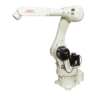
- Page 1 CR860 Controller RV-35FR/50FR/80FR Series Standard Specifications Manual RV-35FR RV-35FRM RV-50FR RV-50FRM RV-80FR RV-80FRM...
-
Page 3: Safety Precautions
SAFETY PRECAUTIONS Read the separate Safety Manual thoroughly before using this product. Take precautions as necessary. Before using this product, please read this manual and the relevant manuals carefully and pay full attention to safety to handle the product correctly. The precautions given in this manual are concerned with this product only. - Page 4 ● All teaching work must be carried out by an operator who has received special training. (This also applies to maintenance work with the power source turned ON.) Enforcement of safety training ● For teaching work, prepare a work plan related to the methods and procedures of operating the robot, and to the measures to be taken when an error occurs or when restarting.
- Page 5 B. This shows precaution points given in the "Safety Manual". For details, please read the text of the "Safety Manual". ● When automatic operation of the robot is performed using multiple control devices (GOT, programmable controller, push-button switch), the interlocking of operation rights of the devices, etc. must be designed by the customer.
- Page 6 ● Securely install the hand and tool, and securely grasp the workpiece. Failure to observe this could lead to personal injuries or damage if the object comes off or flies off during operation. ● Securely ground the robot and controller. Failure to observe this could lead to malfunctioning by noise or to electric shock accidents.
- Page 7 ● Use the robot within the environment given in the specifications. Failure to do so could lead to a decrease in reliability or faults. (Temperature, humidity, atmosphere, noise environment, etc.) ● Transport the robot with the designated transportation posture. Transporting the robot in a non-designated posture could lead to personal injuries or faults from dropping or tipping over.
- Page 8 (VPNs), and antivirus solutions. Mitsubishi Electric shall have no responsibility or liability for any problems involving robot trouble and system trouble by unauthorized access, DoS attacks, computer viruses, and other cyberattacks.
-
Page 9: Cr860 Controller
CR860 controller When installing or connecting a unit or cable to inside the robot controller, do not touch the conductive parts, circuit boards, or electronic components directly. Failure to observe this may result in malfunction or failure of the controller. Cautions for the basic system structure are shown below. - Page 10 Press down the terminal cover of the earth leakage breaker (removed in step 3) until the cover snaps into place. Close the controller front door, then fix it using the front door fixing screws. IP54 cannot be satisfied unless the front door fixing screws are fixed.
-
Page 11: Introduction
To comply with the target application, a work system having a well-balanced robot arm, peripheral devices or robot hand section must be structured. When creating these standard specifications, we have edited them so that the Mitsubishi Electric robot's characteristics and specifications can be easily understood by users considering the implementation of robots. However, if there are any unclear points, please contact your nearest Mitsubishi Electric branch or dealer. -
Page 12: Table Of Contents
CONTENTS SAFETY PRECAUTIONS ..............1 CR860 controller . - Page 13 Example of air supply circuit for hand ............43 About the installation of tooling wiring and piping .
- Page 14 CHAPTER 6 SAFETY Safety ................147 Self-diagnosis stop functions.
-
Page 15: Chapter 1 General Configuration
GENERAL CONFIGURATION Equipment The robot system consists of the following types of equipment. Standard equipment The following table shows items enclosed as standard. Item Standalone type MELSEC iQ-R MELSEC-Q compatible compatible type type Robot arm Robot controller ... -
Page 16: Model Name Of Robot
Model name of robot Robot model names are determined by payload, arm length, and environment specifications. Details are shown below. Select the robot suitable for the customer's application. How to identify the robot model FR - ● RV - Symbol Description Indicates the vertical articulated robot. -
Page 17: Description Of Equipment
Description of equipment Robot arm The devices shown below can be installed on the robot arm. 3-piece machine cable set 6-axis vertical articulated robot (power supply and signal cables) Fixed type: 7m Machine cable extension (replacement) Fixed type: 1F- UCBL-44 Flexible type: 1F- LUCBL-44 Operating range change stopper... -
Page 18: Controller
Controller The devices shown below can be installed on the controller. The controllers that can be connected differ depending on the specifications of the robot arm. Page 14 Model name of robot CR860-D controller Robot controller Transformer unit Simple teaching pendant High-performance teaching CR860-D 2F-ATBOX... - Page 19 Robot controller Transformer unit Robot CPU module CR860-R 2F-ATBOX ・ R16RTCPU The following Mitsubishi Electric MELSEC iQ-R series products are required to install the robot CPU module. The customer needs to prepare them. ・ Base unit ・ Power supply module ・...
- Page 20 • Base unit Model Remarks R35B For mounting MELSEC iQ-R series modules with 5 slots R38B For mounting MELSEC iQ-R series modules with 8 slots R312B For mounting MELSEC iQ-R series modules with 12 slots • Power supply module Model Remarks R61P AC power supply module.
- Page 21 Robot controller Transformer unit Robot CPU module CR860-Q 2F-ATBOX ・ Q172DSRCPU The following Mitsubishi Electric MELSEC Q series products are required to install the robot CPU module. The customer needs to prepare them. ・ Base unit ・ Power supply module ・...
-
Page 22: Function Extension Device
• Base unit Model Remarks Q35B For mounting MELSEC Q series modules with 5 slots Q38B For mounting MELSEC Q series modules with 8 slots Q312DB For mounting MELSEC Q series modules with 12 slots • Power supply module Model Remarks Q61P AC power supply module. -
Page 23: List Of Options
List of options Robot options Product name Model Specifications Remarks Stopper for changing the 1F-DH-44J1 J1 axis The customer should install the optional operating range + side: +180 degrees, +160 degrees, +140 degrees, +120 stopper. degrees, +100 degrees, +80 degrees, +60 degrees, +40 A stopper for changing the operating range degrees, +20 degrees is mounted to a robot arm at shipment. -
Page 24: Function Extension Device
Product name Model Specifications Classification Remarks External I/O cable 2A-CBL05 Used to connect between the external I/O unit (For the parallel I/O and the peripheral. 2A-CBL15 unit) CC-Link interface 2D-TZ576 Only supported with intelligent Used to connect a MELSEC programmable device stations and local stations controller via CC-Link. -
Page 25: Communication Cable
USB cable The following table lists recommended USB cables. Product name Model Supplier Outside dimensions USB cable GT09-C30USB-5P Mitsubishi Electric Page 23 USB cable (GT09- (USB Type-A to Mini USB Type-B) C30USB-5P) Page 23 USB cable (MR- MR-J3USBCBL3M Mitsubishi Electric J3USBCBL3M) ■USB cable (GT09-C30USB-5P) -
Page 26: Chapter 2 Robot Arm
ROBOT ARM Standard specifications Basic specifications Item Unit Specifications RV-35FR RV-50FR RV-80FR Environment specifications Omitted: Normal environment specifications, M: Oil mist specifications Degrees of freedom Installation type Floor mounted Structure Vertical articulated robot Drive system AC servo motor (brake provided on all axes) Position detection method ... -
Page 27: The Counter-Force Applied To The Base Of The Robot
Item Unit Specifications RV-35FR RV-50FR RV-80FR Noise level dB(A) 80 or less Painting color Off-white (Equivalent to Munsell: 10GY9/1) *1 For how to distinguish model names between normal environments and oil mist specifications, refer to the following page: Page 14 How to identify the robot model *2 Values in the table indicate the maximum speed, and the actual speed of each axis varies depending on factors such as the posture, load, and the amount of movement. -
Page 28: Definition Of Specifications
Definition of specifications This section details the specifications listed in catalogs and manuals. Position repeatability For this robot, the pose repeatability is given in accordance with JIS B 8432 (Pose repeatability). Note that the value is based on 100 measurements (although 30 measurements are required according to JIS). The specified "position repeatability"... - Page 29 Load center of gravity • RV-35FR (for the loads with comparatively small volume) Unit: mm 20kg 25kg 35kg J5 axis center of rotation 1000 900 200 100 J6 axis center of rotation *1 The range for the mass of 20kg is specified so that it does not exceed the permissible inertia. •...
-
Page 30: Relationships Among The Payload, Speed, And Acceleration/Deceleration Speed
Relationships among the payload, speed, and acceleration/ deceleration speed This robot automatically sets the optimum acceleration and deceleration speeds and maximum speed, according to the load capacity and size that have been set, and operates using these automatically set speeds. To achieve that, correctly set the actual load data (mass and size of hand and workpiece) to be used. -
Page 31: Grease Leakage During Robot Operation
Grease leakage during robot operation Grease is used in the reduction gears of each axis of the product. Although the grease does not leak from the product structurally, some grease may leak due to initial oozing or long-time use. To prevent grease from adhering to your workpieces and peripheral equipment, check for grease leakage as described in the following manual daily. -
Page 32: Protection Specifications And Applicable Fields
Protection specifications and applicable fields Protection specifications The robot arm has protection specifications that comply with the IEC Standards. The protection specifications and applicable fields are shown below. Model Protection Classification Applicable field Remarks specifications (IEC Standards) RV-35FR, RV-50FR, Equivalent to IP65 Normal environments General assembly. -
Page 33: Part Names
Part names Elbow J4 axis No. 2 arm J5 axis J3 axis Wrist Mechanical interface (flange surface for hand installation) No. 1 arm J6 axis J2 axis Shoulder J1 axis Base 2 ROBOT ARM 2.3 Part names... -
Page 34: 2.4 Outside Dimensions And Operating Range Diagrams
Outside dimensions and operating range diagrams Outside dimensions of robot arm Do not locate the robot arm in direct sunlight or places affected by the heat from lighting. The surface temperature of the robot arm may increase, causing an error. φ8H7 depth 8 6-M6 screw depth 12 φ0.04... -
Page 35: Operating Range Diagram
Operating range diagram The side view figure shows the robot posture when its axes are at the following degrees: J1 = 0 degrees, J2 = 0 degrees, J3 = 90 degrees, J4 = 0 degrees, J5 = 0 degrees, J6 = 0 degrees P-point path (+ side) P-point P-point path (-side) -
Page 36: Outside Dimensions Of Machine Cables
Outside dimensions of machine cables To extend the machine cable, refer to the following page for the diameter of cable. Page 44 Machine cable (replacement) Machine cable (CN1) [Controller side] [Robot side] Weight: 9.9kg Approx. 43 Approx. 135 Approx. 130 Approx. -
Page 37: End-Of-Arm Tooling
End-of-arm tooling Wiring and piping of hands Shows the wiring and piping configuration for a hand. 2)HC 4)LAN 3)GR Elbow 1)PORT A 1)PORT B Mechanical interface No. 2 arm No. 1 arm Primary piping air hose (φ10) PORT A (black), PORT B (white) CN3 (connected to the controller) Base 5)LAN... -
Page 38: Internal Wiring Of The Hand Input Cables
Internal wiring of the hand input cables The hand input cables are wired on the elbow cover and connected to the connector. The name of the connector is "HC". A separate cable is required to connect to the hand. Or an optional hand input cable (1F-HC2000S-44) is required. Ethernet cable The Ethernet cable with eight signal wires runs internally between the base and the No. -
Page 39: Wiring And Piping System Diagram For Hand
Wiring and piping system diagram for hand Shows the system configuration of wiring and piping. Hand input signal connector (HC) +24V DQ397 +24V +24V TXRXH TXRXL +24V HC10 HC11 DQ338 HC12 Hand output signal connector (GR) Primary piping air hose (φ10), black PORT A PORT A Primary piping air hose (φ10), white... -
Page 40: Electrical Specifications Of Hand Input/Output
Electrical specifications of hand input/output Electrical specifications of input circuit Item Specifications Internal circuit Type DC input Overcurrent Input circuit <Sink type> +24V protection Number of input points function Insulation method Photo-coupler insulation 2.8K Iin_p +24V 24V DC 10% Rated voltage Rated current Approx. - Page 41 Electrical specifications of output circuit Item Specifications Internal circuit Type Transistor output Overcurrent Output circuit <Sink type> +24V protection Number of input points function Insulation method Digital isolator 24V DC 10% Rated voltage GRn* Rated current 0.1A/1 point (100%) Overcurrent protection Current leak with power OFF 0.1mA or lower...
- Page 42 Example of current consumption calculation when using the hand I/O ■Sink settings Hand input circuit Hand output circuit Sensors are connected to HC1 to 4, HC9, and HC10 (six Solenoid valves are connected to GR1 to 3 (three points) points) with the sink settings. with the sink settings.
- Page 43 ■Source settings Hand input circuit Hand output circuit Sensors are connected to HC1 to 4, HC9, and HC10 (six Solenoid valves are connected to GR1 to 3 (three points) points) with the source settings. with the source settings. COM(24G) +24V Solenoid valve 1 I1_o Sensor 1...
- Page 44 I/O connector for hand ■Pin assignment of hand input cable Connect the hand input cable to HC. Cable color Pin No. Name Remarks Blue +24 V Twisted pair White Yellow Twisted pair White Twisted pair White Green +24 V Twisted pair White Purple Twisted pair...
-
Page 45: Example Of Air Supply Circuit For Hand
Example of air supply circuit for hand An example of air supply circuit for hand is shown below. • Make sure that a surge voltage protection circuit such as a diode is connected to the solenoid coil in parallel. • If the air pressure drops below the default value, the clamping force of hand will drop, which may interfere with the work. To prevent it, install a pressure switch to the source of the air as shown in the following figure and use the circuit to stop the robot when pressure drops. -
Page 46: Machine Cable (Replacement)
Option There are a variety of options for the robot designed to make the setting up process easier for customer needs. The customer should install the options. Machine cable (replacement) Order type • Fixed type: 1F-UCBL-44 • Flexible type: 1F-LUCBL-44 *1 indicates the cable length. - Page 47 • The guidance of the service life of flexible cables may differ depending on the usage environments (items in the above table) or the amount of silicon grease applied. Recommended silicon grease: G-501 (Supplier: Shin-Etsu Chemical Co., Ltd.) • When a cableveyor is used, partitions are required to avoid overlapping or riding up of the cables. Also, adjust the cable length to eliminate tension or excessive looseness, and fix it securely.
-
Page 48: Operating Range Change Stopper
Operating range change stopper Order type 1F-DH-44J1 Outline The operating range of the J1 axis is limited by installing mechanical stoppers on the robot arm and changing the relevant controller parameter setting. If there is a possibility that the robot will interfere with the peripheral devices or similar situations will arise, the robot can be used safely by limiting the operating range. - Page 49 Changeable angle The operating angle of the J1 axis can be changed in 20-degree increments. For details on the installation positions of the stoppers, refer to the following page: Page 49 Installation procedure J1 axis changeable angle Direction Changeable angle range () Remarks + (plus) side +180...
- Page 50 • Shaded area (cross section Z-Z): Stopper installation position Limit angle () 180 (initial installation position) +100 +120 +140 +160 2 ROBOT ARM 2.6 Option...
- Page 51 Limit angle () -100 -120 -140 -160 When changing the operating range, reposition the stoppers on the robot arm and change the parameter setting. For details, refer to the following manual: Detailed explanations of functions and operations (BFP-A3478) Installation procedure As a safety measure, turn off the control power of the robot controller before installing this option.
- Page 52 Robot front Stopper Stopper M16 × 40 bolt (Loctite #243 applied) View Y Hexagon wrench Robot side view Stopper installation position A Robot front Stopper installation Stopper initial installation position position B (Operating range: ±180°) Cross section Z-Z *1 Purchase Loctite #243 from the following supplier: Henkel Japan Ltd.
-
Page 53: Hand Input Cable
Hand input cable Order type 1F-HC2000S-44 Outline The hand input cable is used for customer-designed pneumatic hands. Use this to receive the open/close confirmation signals and grasping confirmation signals from the hand to the controller. Connect one end of the cable to the connector for the hand input signals, which is on the elbow cover of the robot hand. -
Page 54: Hand Output Cable
Hand output cable Order type 1F-GR2000S-44 Outline The cable is used for customer-designed solenoid valve. Connect one end of the cable to the connector for hand signal output, which is on the elbow cover of the robot arm. The other end of the cable is connected. Configuration Part name Model... -
Page 55: Hand Ethernet Cable
Hand Ethernet cable Order type 1F-LAN2000-44 Outline Use this cable to connect a camera. Connect one end of the cable to the LAN connector inside the No. 2 arm. The other end of the cable is untreated. Select and use a connector according to the usage. -
Page 56: Brake Releasing Device
Brake releasing device Order type 2F-BRKBOX-1 Outline The brakes of the robot arm can be released without using a controller in emergency, such as when the operator got caught in the robot arm and when the posture of the robot arm should be changed in case of the controller failure. Connect this option to the robot arm using the machine cable (CN2) included as standard or an optional power cable for the brake (2F-BRKCBL-1). - Page 57 Installation procedure Brake releasing device Back of the robot arm baset CN2 port Machine cable (CN2) Power off the controller, and remove the machine cable (CN2) from the controller. Connect the connector on the removed machine cable (CN2) to the brake releasing device. (Connect the CN2 port on the robot and the brake releasing device using the machine cable (CN2).) After connecting the connector, engage the lock levers of the port on the brake releasing device with the projections of the connector on the machine cable (CN2) to fix the connector securely.
-
Page 58: Power Cable For The Brake
Power cable for the brake Order type 2F-BRKCBL-1 Outline This cable is used to connect between the brake releasing device and the robot arm and to supply brake power to the robot. If not using the machine cable included as standard, use this cable. Configuration Part name Model... - Page 59 Installation procedure • When connecting and disconnecting the connector, be careful not to get your hand pinched. • When connecting or disconnecting the connector, keep it parallel to the port. If one side is heavily loaded, a connector pin may be damaged, resulting in poor contact.
-
Page 60: About Overhaul
About overhaul Robots which have been in operation for an extended period of time can suffer from wear and other forms of deterioration. In regard to such robots, we define overhaul as an operation to replace parts running out of specified service life or other parts which have been damaged (such as covers), so that the robots can operate continuously. -
Page 61: Maintenance Parts
Purchase these parts from the designated maker or dealer when required. Some Mitsubishi Electric- designated parts differ from the maker's standard parts. Thus, confirm the part name, robot arm, and controller serial number, and purchase the parts from the dealer. -
Page 62: Chapter 3 Robot Controller
ROBOT CONTROLLER Specifications Standard specifications CR860-D controller Item Unit Specifications Remarks Model CR860-VD "" in type name represents the payload of the robot arm. 35: 35kg, 50: 50kg, 80: 80kg Number of axes Simultaneously 6 Up to 8 axes can be added. ... - Page 63 Item Unit Specifications Remarks Construction Self-contained floor type, IP54 (FAN part: IP2X) Enclose type. Ambient In use 0 to 45 Non-freezing temperature At transport/storage -15 to +70 Ambient In use 10 to 85 Non-condensing humidity At transport/storage 90 or lower ...
- Page 64 • CR860-D controller safety performance Function Item Performance Remarks Safety Level SIL3 (IEC 61508:2010) Performance when: • External emergency stop input when the Category 4, PLe (EN ISO 13849-1:2015) test pulse diagnosis settings are enabled MTTFd 100 years Mean time to dangerous failure (MTTFd) Diagnostic coverage (DC) DC = 99% PFH = 1.60 ...
- Page 65 CR860-R controller The CR860-R controller is connected to the robot CPU module mounted on the base unit of the Mitsubishi Electric MELSEC iQ-R series programmable controller. Specifications of the robot CPU module such as the power supply and external dimensions are the same as those specified for the programmable controller.
- Page 66 Item Unit Specifications Remarks Construction Self-contained floor type, Enclose IP54 (FAN part: IP2X) type. Ambient In use 0 to 45 Non-freezing temperature At transport/storage -15 to +70 Ambient In use 10 to 85 Non-condensing humidity At transport/storage 90 or lower ...
- Page 67 • Standard specifications of the robot CPU module (CR860-R controller) Item Unit Specifications Remarks Model R16RTCPU Interface Additional axis interface Port Power supply Power consumption (5V DC) 27.8 (width) 110 (depth) 106 External dimensions ...
- Page 68 CR860-Q controller The CR860-Q controller is connected to the robot CPU module mounted on the base unit of the Mitsubishi Electric MELSEC Q series programmable controller. Specifications of the robot CPU module such as the power supply and external dimensions are the same as those specified for the programmable controller.
- Page 69 Item Unit Specifications Remarks Construction Self-contained floor type, Enclose IP54 (FAN part: IP2X) type. Ambient In use 0 to 45 Non-freezing temperature At transport/storage -15 to +70 Ambient In use 10 to 85 Non-condensing humidity At transport/storage 90 or lower ...
- Page 70 • Standard specifications of the robot CPU module (CR860-Q controller) Item Unit Specifications Remarks Model Q172DSRCPU Interface Additional axis interface Port Power supply Power consumption (5V DC) 1.44 27.4 (width) 120.3 (depth) External dimensions ...
-
Page 71: Protection Specifications And Operating Environments
Protection specifications and operating environments Protection specifications ■How to satisfy IP54 Check the following items to satisfy IP54. • Close the controller front door, then fix it using the front door fixing screws (two places). Front door fixing screw Robot controller front •... - Page 72 Operating environments The controller has a built-in earth leakage breaker, which works based on the power switch. The specifications of the earth leakage breaker are as shown in the following table. Item Unit Specifications Model NV63-CVF 3P 50A 100MA Rated current ...
-
Page 73: Part Names
Part Names Robot controller • Connecting the USB port on the controller to commercially available devices such as computers and LAN hubs may not be compatible with our equipment or the temperature and electrical noise of some FA environments. If using commercially available devices, check the operation carefully to determine if protection against EMI or the addition of a ferrite core is required. - Page 74 Side view Side view Front view Rear view 2): Enlarged view of the operation panel Name Description Power switch Used to switch the control power ON/OFF state (with an earth leakage breaker function). Turning on the servos while the power switch is ON will supply servo power to the motors. Operation panel Operation panel for robot status display, mode switching, emergency stop, computer connection, and other purposes...
- Page 75 *1 The power switch of the CR860 can be locked with a padlock or similar items to prevent operation. The customer needs to prepare a padlock. Page 74 How to use lockout *2 For details on the dummy connector, refer to the T/B installation and removal instructions in the following manual: Controller setup, basic operation, and maintenance (BFP-A3783) Inside the CR860 controller Enlarged view of...
- Page 76 How to use lockout The following shows the procedure for locking the power switch. Turn the handle in the reset direction until the lock plate Handle aligns with the mark on the case. Push the lock plate. Return the handle to the off position with the lock plate pushed.
-
Page 77: Robot Cpu Module
Robot CPU module CR860-R controller Front cover is opened Side view Front view Bottom view Name Description READY LED Indicates the operation status of the robot CPU and an error status. ERROR LED Rotary switch Used for maintenance. Always set 0. Dot matrix LED Indicates the operating status and error details (three digits). - Page 78 CR860-Q controller Front cover is opened Side view Front view Bottom view Name Description Seven segments LED Indicates operating status and error details. Rotary switch (SW1) Set the operation mode. Always set 0. Rotary switch (SW2) Set the operation mode. Always set 0. RUN/STOP switch Not used.
-
Page 79: External Dimensions And Installation Dimensions
External dimensions and installation dimensions External dimensions Robot controller (160) (188) (145) (23) (51) (40) (502) (48) (24) 2 × 2-φ15 hole (15) (15) Bottom view A 3 ROBOT CONTROLLER 3.3 External dimensions and installation dimensions... - Page 80 Robot CPU module ■CR860-R controller 27.8 ■CR860-Q controller 41.1 120.3 27.4 3 ROBOT CONTROLLER 3.3 External dimensions and installation dimensions...
-
Page 81: Installation Dimensions
Installation dimensions Robot controller The controller takes in outside air for cooling, and exhausts the air. The space required for cooling is 100mm or more. Leave a space of 500mm behind the controller for maintenance work. The following figure shows the space required to install the controller. Side: Side: Controller... -
Page 82: External I/O
Page 150 Examples of safety measures By connecting the Mitsubishi Electric indicator, GOT2000 series to the controller via Ethernet, it is possible to control the input/ output of the controller from GOT. 3 ROBOT CONTROLLER 3.4 External I/O... -
Page 83: Dedicated I/O
Dedicated I/O The following table lists the functions of dedicated I/O. For information on other functions, refer to the following manual: Detailed explanations of functions and operations (BFP-A3478) Each parameter is used by designated the signal number, assigned in the order of input signal number and output signal number. - Page 84 Parameter Input Output name Name Function Level Name Function S1STOP Stop input Stops each slot. Waiting output Outputs that each slot is temporarily signal stopped. S32STOP PRGSEL Program Selects the value set for the program selection input number with numeric value input signals. signal ...
-
Page 85: External Emergency Stop I/O/Special Stop Input/Door Switch Input/Enabling Device Input
External emergency stop I/O/special stop input/ door switch input/enabling device input Connecting external emergency stop input, special stop input, door switch input, enabling device input When installing or connecting a unit or cable to inside the robot controller, do not touch the conductive parts, circuit boards, or electronic components directly. Failure to observe this may result in malfunction or failure of the controller. -
Page 86: Connecting Robot Error Output/Emergency Stop Output/Mode Output/Additional Axis Synchronization Output
Connecting robot error output/emergency stop output/mode output/additional axis synchronization output When installing or connecting a unit or cable to inside the robot controller, do not touch the conductive parts, circuit boards, or electronic components directly. Failure to observe this may result in malfunction or failure of the controller. The contact capacity of each output terminal is 24V DC and rated 100mA. -
Page 87: Connecting External Emergency Stop Input, Door Switch Input, Enabling Device Input
Connecting external emergency stop input, door switch input, enabling device input • When installing or connecting a unit or cable to inside the robot controller, do not touch the conductive parts, circuit boards, or electronic components directly. Failure to observe this may result in malfunction or failure of the controller. •... - Page 88 CNUSR11 port Inside the CR860 controller Enlarged view of the R800CPU unit For details on examples of connecting external emergency stop input, door switch input, and enabling device input, positions of dedicated I/O connectors, and pin assignment, refer to the following table. Item Reference Example of connecting external emergency stop input, door switch input,...
- Page 89 Connection diagram of external emergency stop input, door switch input, enabling device input Do not carry out an insulation pressure test. Moreover, incorrect connection may cause a malfunction. Place an external emergency stop switch in an easily operable position, and be sure to wire the switch to the external emergency stop input by referring to the following.
- Page 90 Position of dedicated I/O connectors The following figure shows the position of dedicated I/O connectors. For information on the pin assignment of connectors, refer to the following page: Page 88 Pin assignment CNUSR11 port CNUSR12 port CNUSR13 port Inside the CR860 controller Enlarged view of the R800CPU unit ■Pin assignment •...
- Page 91 • CNUSR12 Name Function Remarks Name Function Remarks SKIP41 SKIP41 input Paired with pin 10 SKIP42 SKIP42 input Paired with pin 1 (common) SKIP31 SKIP31 input Paired with pin 11 SKIP32 SKIP32 input Paired with pin 2 (common) SKIP21 SKIP21 input Paired with pin 12 SKIP22 SKIP22 input...
- Page 92 ■How to wire user wiring connectors The following figure shows the wiring position of user wiring connectors. CNUSR11 connector CNUSR12 connector CNUSR13 connector Enlarged view A: Enlarged view Connector pin numbers of the R800CPU unit The following shows how to wire cables to the connector. User wiring connector Lever Cable...
- Page 93 • To prevent incorrect wiring, carefully check the numbers of the cable insertion hole (connector pin numbers). Connecting a cable to the wrong hole may cause a failure or error of the robot. • When wiring the CNUSR11, CNUSR12, or CNUSR13 connector, pay attention to fraying wires of the core wires. The fraying wires can come into contact with the adjacent terminal, causing a short circuit.
-
Page 94: Special Stop Input (Skip)
Special stop input (SKIP) Do not ground the + side of the customer device's 24V power supply for input/output (emergency stop and parallel I/O) that is used to connect the controller. Connecting the controller with the + side grounded may cause a failure of the controller. The SKIP is the input signal to stop the robot. -
Page 95: Door Switch Functions
Door switch functions This function uses the status of door switches to turn off robot servos when the door of a machine guard is opened. Perform wiring so that the contact opens when the door is opened. For the connection method, refer to the following pages: Page 90 How to wire user wiring connectors Page 150 Examples of safety measures Details of this function according to the robot status are shown below. -
Page 96: Enabling Device Functions
Enabling device functions If an error occurs during an operation such as teaching, operating the switch on the enabling device will power off the robot servos immediately (Servo OFF), thus increasing safety. Always connect an enabling device to use a robot safety. The recommended enabling device is shown below. - Page 97 Required switch statuses for automatic operation, jog operation, and brake release The robot arm may fall under its own weight depending on which brake is released. Take steps such as supporting the arm to prevent it falling under its own weight. The table below shows the required switch statuses for each operation.
-
Page 98: Additional Axis Function
A maximum of eight axes of servo motors can be controlled at the same time by connecting a general-purpose servo amplifier that supports Mitsubishi Electric's SSCNET III. For details on the additional axis function, refer to the following manual: Additional axis function (BFP-A3504) -
Page 99: Additional Axis Synchronization Output
Additional axis synchronization output If the additional axis function is used, the state of an additional axis (servo ON/OFF) can be synchronized with that of the robot arm in the following way: Configuring a circuit so that the power of the servo amplifier for the additional axis can be shut off by opening the output contact (additional axis synchronization output: AXMC) installed in the controller. - Page 100 *3 The following table shows the connector and pin numbers. Signal name Connector Pin No. AXMC11 CNUSR13 AXMC12 AXMC21 AXMC22 *4 If the robot servos are turned off due to an alarm or other reasons, this output (contact) will open. Contact capacity: 24V DC/10mA to 100mA Image of how to connect the connector CNUSR13 port...
-
Page 101: Options
In ISO/10218 (2006) and JIS-B8433 (1993), this is defined as an "enable device". These standards specify that the robot operation using the teaching pendant is enabled only when the "enable device" is at a specified position. With the Mitsubishi Electric industrial robot, the above "enable device" is configured of an "[T/B ENABLE] switch" and "3- position enable switch". - Page 102 ■External dimensions The following figure shows the external dimensions of a teaching pendant. 195.2 105.5 [T/B ENABLE] switch Emergency stop Operetion key Body 3-position enable switch Cable (with connector) <Front> <side> <Back> <Bottom> ■Installation method Connect the teaching pendant to the T/B connection port on the controller. 3 ROBOT CONTROLLER 3.9 Options...
- Page 103 ■Key layout and main functions Name Description [EMERGENCY STOP] switch Brings the robot to an emergency stop, and turns off the servos. [T/B ENABLE] switch Used to switch to enable or disable the operation of the robot with T/B. 3-position enable switch When 2 (Enable) is set for the [T/B ENABLE] switch and the key is released or pressed tightly, the robot servo will turn off and the moving robot will stop immediately.
- Page 104 In ISO/10218 (2006) and JIS-B8433 (1993), this is defined as an "enable device". These standards specify that the robot operation using the teaching pendant is enabled only when the "enable device" is at a specified position. With the Mitsubishi Electric industrial robot, the above "enable device" is configured of an "[TEACH] button" and "3-position enable switch".
- Page 105 ■Installation method Connect the USB memory stick to the T/B connection port on the front of the controller. To take preventive measures against noise, install two ferrite cores as shown below. The ferrite cores are included with the robot controller. Position the ferrite cores within 20cm from the connector.
- Page 106 ■Key layout and main functions Name Description Emergency stop button Brings the robot to an emergency stop, and turns off the servos. Turn the button to the right to release. Display (touch panel) Displays each screen of the T/B. Touch the display with your finger for operation. Wheel Moves the cursor to select each menu, etc.
- Page 107 Safety option ■Order type 4F-SF003-05 ■Outline This unit is used to expand the safety monitoring function. Using this unit with external devices such as a safety switch and light curtain allows you to approach the work area without stopping the robot. ■Configuration Product name Model...
- Page 108 Transformer unit ■Order type 2F-ATBOX ■Outline By using this transformer unit, the robot can be operated with 400V power supply. This transformer unit is used to step down the voltage from 400V to 200V. This transformer unit is designed only for the CR860 controller, and is not used for other controllers.
- Page 109 ■External dimensions (51) or more (502) (28) (24) 3×2-φ15 hole (15) (15) Bottom view A 3 ROBOT CONTROLLER 3.9 Options...
- Page 110 ■Transportation instructions This section explains how to transport the transformer unit. • When transporting only the transformer unit Two workers must transport the transformer unit using a crane or lifter. Wire Eye bolt (M12 × 2) Weight of transformer unit: 120kg •...
- Page 111 ■Installation instructions The following figure shows the dimensions required to install the transformer unit. Side: Side: Transformer unit (top) Anchor bolt attached in 4 places φ14×50 Maintenance area (top view) *1 External vibration may cause the controller to fall or move, resulting in injury. It is recommended to fix the transformer unit. Select anchor bolts that do not come out by more than 50mm from the installation surface.
- Page 112 ■Wiring To avoid electric shock, turn off the primary power supply before wiring. For information on how to connect the power cable or the CR860, refer to the following manual: Controller setup, basic operation, and maintenance (BFP-A3783) The internal wiring of the transformer unit may have to be changed depending on the voltage of the customer's primary side.The transformer unit has taps 1 to 3 each for the U, W, and V phases.
- Page 113 Encoder distribution unit ■Order type 2F-YZ581 ■Outline The encoder distribution unit 2F-YZ581 is used to connect one rotary encoder (hereafter "encoder") to multiple robot controllers. For details on the tracking function, refer to the following manual: Tracking Function (BFP-A3520) ■Configuration Product name Model Quantity...
- Page 114 ■External dimensions Outside dimensions *1 Unit fixing hole *2 DIN rail adapter installation hole *3 Grounding hole *4 Static electricity protection cover installation hole 2-M3(*4) Same for opposite side M3 depth 8(*3) ■Usage Refer to the following manual attached to the robot arm. Tracking Function (BFP-A3520) 3 ROBOT CONTROLLER 3.9 Options...
- Page 115 MELSOFT RT ToolBox3/MELSOFT RT ToolBox3 mini/MELSOFT RT ToolBox3 Pro ■Order type The following software is provided by a DVD-ROM for Windows. • MELSOFT RT ToolBox3: 3F-14C-WINE • MELSOFT RT ToolBox3 mini: 3F-15C-WINE • MELSOFT RT ToolBox3 Pro: 3F-16D-WINE ■Outline RT ToolBox3 has a wide range of uses, which include assisting with program design (editing and creation), setup (program execution, management, debugging), maintenance (maintenance forecast), and checking robot specifications (tact time etc.).
- Page 116 ■Function : Available, : Not available Function Availability Details Compatible model Personal computer running Windows 10 or Windows 11 Program Editing function • MELFA BASIC V and VI language compatible editing • Multiple editing screen simultaneously display functions •...
- Page 117 Instruction Manual (hard copy) ■Order type • 5F-BT01-PE01: A digital copy of the RV-35FR/50FR/80FR series instruction manuals. ■Outline The hard copy of CD-ROM attached to this product. ■Configuration Product name Model Weight Details (kg) Instruction 5F-BT01-PE01 A digital copy of the RV-35FR/50FR/80FR series instruction manuals. manual ...
-
Page 118: Options For Cr860-D Controller
Options for CR860-D controller Parallel I/O interface The combined use with another option, parallel I/O unit (2A-RZ361/2A-RZ371), is also possible. In this case, use a different station number for each unit. The station number is automatically determined by the position of the option slot to which the interface is installed. (Station number 0 to 1) ■Order type •... - Page 119 ■Specifications The protection fuse of the output circuit prevents the failure at the time of the load short circuit and incorrect connection. The load connected of the customer should be careful not to exceed maximum rated current. The internal transistor may be damaged if maximum rated current is exceeded. The electrical specifications of input circuit are shown below.
- Page 120 ■Installation method When using the parallel I/O unit 2A-RZ361/2A-RZ371 together with the parallel I/O interface, use a number different from that of the parallel I/O interface. Inside the CR860 controller SLOT1 SLOT2 Enlarged view of the R800CPU unit Install the parallel I/O interface to the R800CPU unit. Install it referring to the following. Controller setup, basic operation, and maintenance (BFP-A3783) If it is installed to the option slot of the controller, the station number will be assigned automatically.
- Page 121 The following table lists the pin number of the connector on the parallel I/O interface connected to SLOT1 and the signal assignment. If installing the interface to other slots, interpret and utilize. • List of the connector <1> signal assignment and the color of external I/O cable 2D-CBL(SLOT1) Cable color Function name Cable color...
- Page 122 • List of the connector <2> signal assignment and the color of external I/O cable 2D-CBL(SLOT1) Cable color Function name Cable color Function name Signal name Power supply/common Signal name Power supply/common Orange/Red a 24G/12G: For the pins of 5B to Orange/Black a +24V/+12V (COM): For the pins of 5B to 20B...
- Page 123 The example of connection with a Mitsubishi Electric programmable controller (sink type) is shown below. • The customer should supply the external power supply (24V DC) for the I/O circuit. • Do not ground the + side of the customer device's 24V power supply for input/output (emergency stop and parallel I/O) that is used to connect the controller.
- Page 124 The example of connection with a Mitsubishi Electric programmable controller (source type) is shown below. • The customer should supply the external power supply (24V DC) for the I/O circuit. • Do not ground the + side of the customer device's 24V power supply for input/output (emergency stop and parallel I/O) that is used to connect the controller.
- Page 125 External I/O cable ■Order type • 2D-CBL *1 indicates the length of cable. (05: 5m, 15: 15m) ■Outline This is the cable dedicated to connecting an external peripheral to the connector on the parallel I/O interface. Use another option 2A-CBLfor the parallel I/O unit. One end matches the connector on the parallel I/O interface, and the other end is free.
- Page 126 ■Connection and external dimensions The sheath of each signal cable (40 lines) is indicated its color and marked with dots. Connect each cable referring to the following figure. Page 123 Connector pin number and cable color (Example) Pin number: Color indication : Orange/Red/a Type of dot mark Color of dot mark...
- Page 127 Parallel I/O unit ■Order type • 2A-RZ361 (sink type)/2A-RZ371 (source type) ■Outline This unit is used to expand the external inputs and outputs. • The connection cable is not included. The external I/O cable (2A-CBL05 or 2A-CBL15) can be provided as the option.
- Page 128 The electrical specifications of input circuit are shown below. Item Specifications Internal circuit Type Transistor output <Sink type> Number of output points +24V/+12V Insulation method Photo-coupler insulation Output Rated load voltage 12V DC/24V DC Rated load voltage range 10.2 to 30V DC (peak voltage: 30V DC) Maximum load current 0.1A/point (100%)
- Page 129 NET cable-1 (network cable) Pin No. RIO1/2 Pin No. TXRXH TXRXDH TXRXL TXRXDL SG(GND) SG(GND) Connector: 1-178288-3 Connector: J21DF-06V-KX-L DCcable-2 (power cable) Pin No. RIO1/2 +24V power supply FG(PE) Connected to the frame Connector: 2-178288-3 or protective earth R-TM (terminator) Pin No.
- Page 130 ■Installation method Install the expansion parallel I/O unit outside the controller. Connect it using the network connection cable (NETcable-1) from the RIO port on the front of the R800CPU unit. The following figure shows the installation method of the parallel I/O unit. RIO port Inside the CR860 controller Enlarged view of the R800CPU unit...
- Page 131 The following figure shows the installation method of the expansion parallel I/O unit. Within 100mm*1 Parallel I/O unit 1 to 6 Parallel I/O unit 7 Station No. setting Station No. setting 1 to 6 RIO port <CN300> <CN300> <CN100> <CN100> NETcable-1 cable RIO2...
- Page 132 ■Pin arrangement of connector The following figure shows the pin arrangement of the parallel I/O interface. 2A-RZ361/2A-RZ371 has 32 input points and 32 output points (1 station occupied). Station No. setting LED indicator*1 <CN300> Input 16 to 31 Output 16 to 31 (station No.: 0) <CN100>...
- Page 133 The following table lists the pin number of the connector on the parallel I/O interface of station number 0 and the signal assignment. If installing the interface to other station numbers, interpret and utilize. • List of the connector CN100 signal assignment and the color of external I/O cable 2A-CBL(station number 0) Cable color Function name Cable color...
- Page 134 • List of the connector CN300 signal assignment and the color of external I/O cable 2A-CBL(station number 0) Cable color Function name Cable color Function name General- Dedicated/Power supply, General- Dedicated/Power supply, purpose common purpose common Orange/Red A Orange/Blue A ...
- Page 135 The example of connection with a Mitsubishi Electric programmable controller (sink type) is shown below. • The customer should supply the external power supply (24V DC) for the I/O circuit. • Do not ground the + side of the customer device's 24V power supply for input/output (emergency stop and parallel I/O) that is used to connect the controller.
- Page 136 The example of connection with a Mitsubishi Electric programmable controller (source type) is shown below. • The customer should supply the external power supply (24V DC) for the I/O circuit. • Do not ground the + side of the customer device's 24V power supply for input/output (emergency stop and parallel I/O) that is used to connect the controller.
- Page 137 External I/O cable ■Order type • 2A-CBL *1 indicates the length of cable. (05: 5m, 15: 15m) ■Outline This is the cable dedicated to connecting an external peripheral to the connector on the parallel I/O unit. Use another option 2D-CBLfor the parallel I/O interface. One end matches the connector on the parallel I/O unit, and the other end is free.
- Page 138 ■Connection and external dimensions The sheath of each signal cable (40 lines) is indicated its color and marked with dots. Connect each cable referring to the following figure. Page 135 Connector pin number and cable color (Example) Pin number: Color indication : Orange/Red/a Type of dot mark Color of dot mark...
- Page 139 CC-Link interface ■Order type • 2D-TZ576 ■Outline The CC-Link interface is the optional interface to add the CC-Link Field Network function that sends word data as well as bit data to the robot controller using cyclic transmission. ■Configuration The following table lists the components. Product name Model Quantity...
- Page 140 ■Specifications Item Specifications Remarks Communication function Bit data and word data can be transmitted. Word data is used in register areas. Station type Intelligent device station Support station Local station No master station function Version corresponding to CC-Link Ver.2 The extended cyclic transmission can be set.
- Page 141 ■Function • Communication function The number of usable points is 896 maximum for bit control and 128 maximum for word control. • Easy setup The CC-Link interface card can be set using parameters. The CC-Link interface card is built in the robot controller. Thus, no separate space is required. Easy wiring since only four terminals need to be connected.
-
Page 142: Maintenance Parts
The consumable parts used in the controller are shown in the following table. Purchase these parts from the designated maker or dealer when required. Some Mitsubishi Electric-designated parts differ from the maker's standard parts. Thus, confirm the part name, robot arm, and controller serial number, and purchase the parts from the dealer. -
Page 143: Chapter 4 Software
SOFTWARE List of commands The following table lists the main functions of MELFA-BASIC VI. Type Class Function Input format (example) Structured Function Defines the Function procedure. Function M Func(M1, M2) programming procedure Function procedure summarizes a series of processing enclosed by the Function M3=M1+M2 statement and the FEnd statement. - Page 144 Type Class Function Input format (example) Program Branching Branches unconditionally to the designated place. GoTo *LBL control Branches according to the designated conditions. If M1=1 Then GoTo *L100 Else GoTo *L200 EndIf Repeats the operation until the specified end conditions are satisfied. For M1=1 To 10 ...
- Page 145 Type Class Function Input format (example) Others Definition Defines the integer variables or real number variables. Def Inte KAISUU Defines the character string variables. Def Char MESSAGE Defines the array variables. (Three-dimensional array can be set.) Dim PDATA(2,3) Defines the joint variables. Def Jnt TAIHI Defines the position variables.
-
Page 146: List Of Parameters
List of parameters The following table lists the main parameters. Parameter Details Standard tool coordinate MEXTL Set the default value for the tool data. Unit: mm or deg Standard base coordinate MEXBS Set the relation between the base coordinate system and robot coordinate system. Unit: mm or deg XYZ operating range MEPAR... - Page 147 Parameter Details Communication setting CBAU232 Set the baud rate. CLEN232 Set the character length. CPRTY232 Set the parity. CSTOP232 Set the stop bit. CTERM232 Set the end code. Slot table SLT1 Set the specifications for each slot (program name, operation type, order of priority, etc.) at initialization of ...
-
Page 148: Chapter 5 Instruction Manual
INSTRUCTION MANUAL Details of each instruction manual The following table shows contents and purposes of the documents enclosed with this product. Use these documents according to the application. For special specifications, a separate instruction manual describing the special section may be enclosed. Manual name Description Safety Manual... -
Page 149: Chapter 6 Safety
SAFETY Safety Measures to be taken regarding safety of the industrial robot are specified in the "Labor Safety and Sanitation Rules". Always follow these rules when using the robot to ensure safety. Self-diagnosis stop functions This robot has the self-diagnosis functions shown in the following tables for safe use. •... -
Page 150: External I/O Signals That Can Be Used For Preventative Safety Measures
External I/O signals that can be used for preventative safety measures The following table list the external I/O signals that can be used for preventative safety measures. Signal Connection port Parameter Function Usage method Input External emergency stop Connector CNUSR11 Shuts off the servo power and Emergency stop switches to be input... -
Page 151: Safety Measures For Automatic Operation
Work procedures • Create and observe work procedures for the robot teaching, operation, inspection and emergencies. • Create hand signals to be followed when several operators are working together. • Create displays such as "Teaching in Progress" and "Inspection in Progress" to be put up when an operator is in the operating range of the robot so that other operators will not operate the operation panel (controller, control panel). -
Page 152: Examples Of Safety Measures
Examples of safety measures • In the process of wiring customer's emergency stop-related products, if connecting the coil (not a contact) of the relay supplied by customer to the controller, be sure to take preventive measures against surge in the coil section. Moreover, take the service life of surge protective devices into consideration. •... - Page 153 *1 This is the emergency stop button on the front of the robot controller. *2 This is the emergency stop button of the T/B that is connected to the robot controller. *3 The CNUSR11 connector has two rows of terminals, indicating that there are two channels. Both channels must be connected. *4 The terminals are open (unconnected) from the factory.
- Page 154 Wiring example 3 Connect the peripheral equipment's emergency stop switch, door switch, and enabling device. The power used for emergency stop detection is supplied via the peripheral equipment. The emergency stop state is monitored via the peripheral equipment. This wiring example shows that the OP emergency stop, T/B emergency stop, and external emergency stop switches are connected on one path.
- Page 155 Wiring example 4 Connect the peripheral equipment's emergency stop switch and door switch to two controllers for interlocking. The power used for emergency stop detection is supplied from the controller. The emergency stop state is monitored via the peripheral equipment. <Operation of the emergency stop>...
- Page 156 • When connecting a safety relay to the system and using the emergency stop button of the controller as an input to the relay, select a safety relay that functions when a signal is input to either one of the two inputs. (Example: QS90SR2SP manufactured by Mitsubishi Electric) •...
- Page 157 Connecting an external emergency stop switch [supplementary explanation] • Be sure to perform wiring correctly. Incorrect wiring cannot bring the robot to an emergency stop, and this may result in property damage or bodily injury. After wiring, be sure to press each of the installed emergency stop switches and check whether the emergency stop circuit works properly. •...
- Page 158 ■Current value limit for connection with devices such as exciting coils of relays OP emergency +24V CNUSR11 stop button Peripheral equipment +3.3V 24V power supply 17/12 T/B emergency stop button Emergency stop switch Peripheral 18/13 (2-contact type) equipment +24V 16/11 +3.3V +3.3V Relay...
-
Page 159: Operating Environments
Operating environments Do not install the product in the following environments, or its life may be shortened or operation may be affected. If you use the product in the following environments, take precautionary actions beforehand. Power supply The input power voltage fluctuation rate of the robot controller must be within the range from +10% to -15%. Ensure that the primary power voltage does not drop below 170VAC due to the robot arm operation or voltage change. -
Page 160: Handling Precautions
• When the programmable controller system becomes large too much, the robot locus may deteriorate. In this case, please contact your nearest Mitsubishi Electric branch or dealer. And, when it turns out that the system is enlarged in advance, please inform our company. - Page 161 • The United Nations' Recommendations on the Transport of Dangerous Goods must be observed for transborder transportation of lithium batteries by air, sea, and land. The batteries (1S1P×2 LS17500, Q6BAT) used in Mitsubishi Electric industrial robots contain lithium and fall under the definition. When the lithium batteries are shipped for storage, they will be classified as Class 9: Miscellaneous dangerous substances and articles.
-
Page 162: Emc Installation Guideline
EMC installation guideline Outline Industrial robots are one of the components of automation systems as well as main components. This section introduces methods and parts to ensure electromagnetic compatibility (EMC) in automation systems. We test for EMC in the environment described in this manual, but the noise level varies depending on the step-down transformer (supplied by customer), device layout, and wiring, etc. -
Page 163: Example Of Emc Measures
MTFX40 ZIPPERTUBING(JAPAN), LTD. Parts for EMC measures For details on the parts for EMC measures described in example of EMC measures, contact your nearest Mitsubishi Electric branch or dealer. For an example of EMC measures, refer to the following page: Page 161 Example of EMC measures... -
Page 164: Appendix
APPENDIX Appendix 1 Inertia calculation method An allowable moment of inertia is determined in the mechanical interface at the tip of the robot arm. If a load exceeding the allowable moment of inertia is put on the tip of the arm, vibration during operation and an overload alarm may occur. Therefore, consider the matching/appropriateness of the hand and load to be mounted on the tip of the arm for the robot specifications when you select a robot. -
Page 165: Appendix 2 Classification Of External I/O Functions
Appendix 2 Classification of external I/O functions Take note of the following information regarding external I/O functions. Classification Function Description Safety signal External emergency stop This function detects emergency stop inputs. The STO function will meet SIL3, PLe/Category 4 input standard when the safety diagnosis function of the emergency stop input circuit is enabled. -
Page 166: Appendix 3 Safety Diagnosis Function (Test Pulse Diagnosis)
Appendix 3 Safety diagnosis function (test pulse diagnosis) The Safety diagnosis function checks the emergency stop status of the robot using the pulse output from the emergency stop signals (EXTEMG11, EXTEMG21). By changing the settings of TPOEMG, off pulses can be output regularly from EXTEMG11 and EXTEMG21. -
Page 167: Appendix 4 Safety Block Diagram
Appendix 4 Safety block diagram Robot arm Robot controller Inverter Current sensor AC200V PWM gate circuit Current feedback Servo CPU block Encoder feedback Gate control Servo Block signal Encoder feedback Feed Position data back Emergency stop Safety function input block 1 Signal Signal Channel A... -
Page 168: Appendix 5 Declaration Of Conformity
CE mark: EU Declaration of Conformity UKCA mark: UK Declaration of Conformity Each Declaration of Conformity describes the following information. Information Description Manufacturer MITSUBISHI ELECTRIC CORPORATION Address TOKYO 100-8310, JAPAN Authorized representative in Europe MITSUBISHI ELCTRIC EUROPE B.V., German Branch Address... -
Page 169: Appendix 6 Specifications Discussion Material (Rv-35Fr/50Fr/80Fr Series)
Appendix 6 Specifications discussion material (RV- 35FR/50FR/80FR series) Customer information Company name: Name: Address: Telephone: Purchased model Specifications Robot arm Robot controller Normal environment RV-35FR-D RV-50FR-D RV-80FR-D CR860-**VD RV-35FR-R RV-50FR-R RV-80FR-R CR860-**VR RV-35FR-Q RV-50FR-Q RV-80FR-Q CR860-**VQ Oil mist RV-35FRM-D RV-50FRM-D RV-80FRM-D CR860-**VD RV-35FRM-R... -
Page 170: Options (Installable After Shipment)
Options (Installable after shipment) Item Model Provided or not, specifications when provided Robot Machine cable 1F-UCBL-44 Fixed type: 12m 17m 22m 1F-LUCBL-44 Flexible type: 7m 12m 17m 22m Hand input cable 1F-HC2000S-44 Not provided 1F-HC2000S-44 Hand output cable 1F-GR2000S-44 Not provided 1F-GR2000S-44 Hand Ethernet cable 1F-LAN2000-44 Not provided Provided... -
Page 171: Revisions
• Changed some sections. This manual confers no industrial property rights or any rights of any other kind, nor does it confer any patent licenses. Mitsubishi Electric Corporation cannot be held responsible for any problems involving industrial property rights which may occur as a result of using the contents noted in this manual. -
Page 172: Trademarks
TRADEMARKS No part of this manual may be reproduced by any means or in any form, without prior consent from Mitsubishi Electric. The details of this manual are subject to change without notice. The specification value is based on our standard test method. - Page 174 BFP-A3779-B(2403)MEE HEAD OFFICE: TOKYO BLDG., 2-7-3, MARUNOUCHI, CHIYODA-KU, TOKYO 100-8310, JAPAN NAGOYA WORKS: 1-14, YADA-MINAMI 5-CHOME, HIGASHI-KU, NAGOYA 461-8670, JAPAN Specifications subject to change without notice.
Need help?
Do you have a question about the MELFA CR860 Series and is the answer not in the manual?
Questions and answers