
Related Manuals for Beckhoff KL6811


Summary of Contents for Beckhoff KL6811
- Page 1 Documentation | EN KL6811 DALI/DSI Master Terminal with integrated Power Supply 2020-11-02 | Version: 2.0.0...
-
Page 3: Table Of Contents
Connection system .......................... 14 Connection ............................ 18 ATEX - Special conditions (standard temperature range) ............... 19 Continuative documentation about explosion protection .............. 20 4 Configuration software KS2000 ...................... 21 KS2000 - Introduction ........................ 21 KL6811 configuration........................ 23 Register ............................ 25 Settings............................ 25 4.4.1 Setting up the DALI/DSI devices .................. 26 4.4.2 Addressing the DALI devices................... - Page 4 Table of contents Version: 2.0.0 KL6811...
-
Page 5: Foreword
EP1590927, EP1789857, EP1456722, EP2137893, DE102015105702 with corresponding applications or registrations in various other countries. ® EtherCAT is registered trademark and patented technology, licensed by Beckhoff Automation GmbH, Germany. Copyright © Beckhoff Automation GmbH & Co. KG, Germany. The reproduction, distribution and utilization of this document as well as the communication of its contents to others without express authorization are prohibited. -
Page 6: Safety Instructions
All the components are supplied in particular hardware and software configurations appropriate for the application. Modifications to hardware or software configurations other than those described in the documentation are not permitted, and nullify the liability of Beckhoff Automation GmbH & Co. KG. Personnel qualification This description is only intended for trained specialists in control, automation and drive engineering who are familiar with the applicable national standards. -
Page 7: Documentation Issue Status
• Mounting rail installation updated • Basic function principles updated 1.2.1 • LED descriptions updated • Product overview restructured • Parameterization description for KL6811 and DALI devices with KS2000 software expanded • Status byte descriptions expanded • Technical data updated • Register description corrected •... - Page 8 FF - firmware version HH - hardware version Example with ser. no.: 35 04 1B 01: 35 - week of production 35 04 - year of production 2004 1B - firmware version 1B 01 - hardware version 01 Version: 2.0.0 KL6811...
-
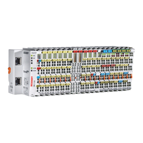
Page 9: Product Overview
Introduction Fig. 1: KL6811 The KL6811 enables the connection of up to 64 DALI slaves. The KS2000 configuration software facilitates parameterization via a PC. The PC is directly coupled with the Bus Coupler via an RS232 interface or via the fieldbus. The KL6811 features an integrated power supply unit (24 V ) with electrically isolated output voltage. -
Page 10: Technical Data
Product overview Technical data Technical data KL6811, KS6811 Data transfer channels DALI slaves / groups maximum 64 / maximum 16 Bit width in the K-bus I/O 2 x 8 bit user data, 1 x 8 bit control/status Bit width in the input process image... -
Page 11: Led Indicators
Bus Coupler. The KL6811 can also be operated as a DSI master. The Digital Serial interface (DSI) is an even simpler bus system for lighting control. The DSI master sends digital light intensity values serially to the DSI slaves. The brightness of the slaves can be set between 1% and 100%. -
Page 12: Mounting And Wiring
To mount the mounting rails with a height of 7.5 mm under the terminals and couplers, you should use flat mounting connections (e.g. countersunk screws or blind rivets). Version: 2.0.0 KL6811... -
Page 13: Fig. 4 Disassembling Of Terminal
EL91xx, EL92xx) interrupt the power contacts and thus represent the start of a new supply rail. PE power contact The power contact labeled PE can be used as a protective earth. For safety reasons this contact mates first when plugging together, and can ground short-circuit currents of up to 125 A. KL6811 Version: 2.0.0... -
Page 14: Connection System
• The terminals of KSxxxx and ESxxxx series feature a pluggable connection level and enable steady wiring while replacing. • The High Density Terminals (HD Terminals) include electronics and connection level in a single enclosure and have advanced packaging density. Version: 2.0.0 KL6811... -
Page 15: Fig. 6 Standard Wiring
12 mm Bus Terminals. Massive conductors and conductors with a wire end sleeve can be inserted directly into the spring loaded terminal point without tools. KL6811 Version: 2.0.0... -
Page 16: Fig. 9 Mounting A Cable On A Terminal Connection
The cables are released, as usual, using the contact release with the aid of a screwdriver. See the following table for the suitable wire size width. Version: 2.0.0 KL6811... - Page 17 Wire size width (fine-wire conductors) 0.25 ... 1.5 mm Wire size width (ultrasonically “bonded" conductors) only 1.5 mm (see notice [} 16]!) Wire stripping length 8 ... 9 mm Shielding Shielding Analog sensors and actors should always be connected with shielded, twisted paired wires. KL6811 Version: 2.0.0...
-
Page 18: Connection
No mains voltage at the power contacts The terminal points for the power contacts (+24 V, 0 V) must not be connected to 230 V mains voltage un- der any circumstances, since this would destroy the KL6811. Contacts for the DALI control cable (DALI+, DALI-) and mains voltage If the contacts for the DALI control line (DALI+, DALI-) are accidentally connected to 230 V mains voltage, the KL6811 is not destroyed, but switches off. -
Page 19: Atex - Special Conditions (Standard Temperature Range)
80°C at the wire branching points, then cables must be selected whose tempera- ture data correspond to the actual measured temperature values! • Observe the permissible ambient temperature range of 0 to 55°C for the use of Beckhoff fieldbus compo- nents standard temperature range in potentially explosive areas! •... -
Page 20: Continuative Documentation About Explosion Protection
Explosion protection for terminal systems Pay also attention to the continuative documentation Notes on the use of the Beckhoff terminal systems in hazardous areas according to ATEX and IECEx that is available for download on the Beckhoff homepage https:\\www.beckhoff.com! Version: 2.0.0... -
Page 21: Configuration Software Ks2000
Fieldbus Box modules with the aid of which settings can be modified easily. Alternatively, you have full access to all internal registers of the bus couplers and intelligent terminals. Refer to the register description for the meanings of the registers. KL6811 Version: 2.0.0... - Page 22 • Process values can be specified in the output image for commissioning of the output modules. All possibilities in the online mode can be used in parallel with the actual fieldbus mode of the terminal station. The fieldbus protocol always has the higher priority in this case. Version: 2.0.0 KL6811...
-
Page 23: Kl6811 Configuration
In the example shown, this is • a BK9000 Bus Coupler for Ethernet • a KL1xx2 digital input terminal • a KL6811 DALI Master Terminal • a KL9010 bus end terminal Fig. 12: Display of the fieldbus station in KS2000 The left-hand KS2000 window displays the terminals of the fieldbus station in a tree structure. -
Page 24: Fig. 13 Ks2000 Tree Branches For Channel 1 Of The Kl6811
For the KL6811, the branches Register, Settings and ProcData are displayed: • Register [} 25] enables direct access to the KL6811 registers. • Under Settings [} 25] you find dialog boxes for parameterizing the KL6811. • ProcData displays the KL6811 process data. -
Page 25: Register
Configuration software KS2000 Register You can access the registers of the KL6811 directly under Register. The meaning of the register is explained in the register overview [} 46]. Fig. 14: Register view in KS2000 Settings Under Settings you will find the dialog masks for parameterization of the KL6811 and of the DALI/DSI devices connected to it. -
Page 26: Setting Up The Dali/Dsi Devices
You can specify a number of options for the KL6811 [} 39] on this tab. 4.4.1 Setting up the DALI/DSI devices Click the Scan devices button so that the KL6811 reads in the connected DALI/DSI devices. In this example, 6 DALI devices are shown. Sending DALI commands Click on Devices. -
Page 27: Fig. 16 Ks2000 - Parameterization Of The Dali/Dsi Devices - Address-Type
• set the intensity slider to the desired value or • enter a value into the Data field and click the Send DALI command button. The KL6811 sends this value as a direct DALI command [} 53] for the lamp power to all the selected DALI devices. -
Page 28: Fig. 17 Ks2000 - Parameterization Of The Dali/Dsi Devices - Visual Selection Feedback
• set the intensity slider to the desired value or • enter a value into the Data field and click the Send DSI command button. The KL6811 sends this value to all the connected DSI devices. Fig. 18: KS2000 - parameterization of the DALI/DSI devices - sending of DSI commands 4.4.1.1... -
Page 29: Fig. 19 Ks2000 - Parameterization Of The Dali/Dsi Devices - Lighting Control / Queries
Variables [} 31] tab. Step Up Sets the current lamp power value one graduation higher without fading (sends DALI command 3 [} 53] unless it is already switched on. If the lamp is switched off, it is not switched on. KL6811 Version: 2.0.0... - Page 30 Asks whether a limit value error has occurred on the DALI device (DALI command 148 [} 55] Query reset status Asks whether the DALI device is in the reset state (DALI command 149 [} 55] Query missing short address Asks whether the DALI device is missing the short address (DALI command 150 [} 55] Version: 2.0.0 KL6811...
-
Page 31: Fig. 20 Ks2000 - Parameterization Of The Dali/Dsi Devices - Variables
This variable contains the power currently applying to the lamp. Power ON level This variable specifies the lamp power that the DALI device is to adopt after the power supply has been switched on, if the DALI bus is already under power and is idle. KL6811 Version: 2.0.0... - Page 32 The absolute fade time is not entered directly, but it is calculated according to the following formula: T = absolute fade time n = value that is stored in the Fade time variable Version: 2.0.0 KL6811...
- Page 33 Displays the DALI device's version number. This variable is entered by the device manufacturer, and can only be read! Physical minimum level Indicates the lowest physically possible lamp power that the DALI device can adopt. This variable is entered by the device manufacturer, and can only be read! KL6811 Version: 2.0.0...
-
Page 34: Fig. 21 Ks2000 - Parameterization Of The Dali/Dsi Devices - Groups
(e.g. in the context of a broadcast), it will set the intensity specified for this scene. If the value 255 (mask) is specified for this scene, the DALI device retains its previous value. Version: 2.0.0 KL6811... -
Page 35: Addressing The Dali Devices
Configuration software KS2000 Fig. 22: KS2000 - parameterization of the DALI/DSI devices - scenes 4.4.2 Addressing the DALI devices Physical selection Fig. 23: KS2000 - addressing of the DALI device - physical selection KL6811 Version: 2.0.0... -
Page 36: Fig. 24 Ks2000 - Addressing Of The Dali Device - Displaying The Physical Addressing
5. When you have assigned all the addresses, complete the addressing procedure by clicking the Cancel button. The newly addressed devices will be shown in the list of short addresses: Fig. 24: KS2000 - addressing of the DALI device - displaying the physical addressing Random addressing With this method, addresses are assigned randomly. Version: 2.0.0 KL6811... -
Page 37: Fig. 25 Ks2000 - Addressing Of The Dali Device - Random Addressing
Fig. 26: KS2000 - addressing the DALI devices - displaying the randomly assigned addresses Single assignment With this method, all DALI slaves connected to the KL6811 are assigned the same new address. In practice, only the one DALI slave, which is to be assigned this address, will therefore be connected, before the Start button is pressed. -
Page 38: Fig. 27 Ks2000 - Addressing Of The Dali Devices - Single Assignment
Fig. 28: KS2000 - addressing of the DALI devices - Modify addresses Visual selection feedback If the option visual selection feedback is enabled, the selected device (in the example device #04) sets its current lamp power value to the parameterized maximum value. Version: 2.0.0 KL6811... -
Page 39: Options
You can switch off the DALI/DSI power supply unit here. Count DALI devices (R32.4 [} 47]) Here you can disable the counting of the DALI devices after the KL6811 startup. Firmware version (R9 [} 47]) Displays the firmware version of the KL6811 . -
Page 40: Fig. 30 Ks2000 - Archive - Groups
If the option visual selection feedback is enabled and you click on a group number, the brightness of all DALI slaves of this group is set to maximum. This also requires Online Monitoring to be enabled under Options in the KS2000, and the I/O Run LED on the Bus Coupler must be on. Version: 2.0.0 KL6811... -
Page 41: Fig. 31 Options
Saves the configuration in a file (*.xml) on the hard disk of the PC. Download Saves the configuration in the connected DALI slaves. Upload Loads the configuration from the connected DALI slaves. 4.4.4.2 Scenes Fig. 32: KS2000 - archive - scenes KL6811 Version: 2.0.0... -
Page 42: Process Data
This also requires Online Monitoring to be enabled under Options in the KS2000, and the I/O Run LED on the Bus Coupler must be on. Process data The process data is represented graphically under ProcData. Version: 2.0.0 KL6811... -
Page 43: Access From The User Program
Access from the user program Access from the user program Process image In the process image, the KL6811 is represented with 3 bytes of input and output data. These are organized as follows: Byte offset (without word Byte offset (with word... -
Page 44: Control And Status Byte
(SB.0 [} 44]). Status byte in process data mode The status byte (SB) is located in the input image [} 43], and is transmitted from KL6811 to the controller. Version: 2.0.0... - Page 45 Error No error Error: • In DALI mode if the internal DALI power supply unit of the KL6811 is used: overload of the internal DALI power supply unit of the KL6811 (bus under-voltage) • In DSI mode: error message from one (or several) of the DSI devices SB.5 to SB.3 -...
-
Page 46: Register Overview
It is not possible to access the data registers during register communication! Process data that may still be displayed is not valid! Status byte for register communication The status byte (SB) is located in the input image [} 43], and is transmitted from KL6811 to the controller. SB.7 SB.6 SB.5... - Page 47 RAM registers and in the EPROM registers and are therefore retained if the terminal is restarted. The code word is reset if the terminal is restarted. R32: Feature register The feature register specifies the terminal's operating mode. KL6811 Version: 2.0.0...
-
Page 48: Examples Of Register Communication
R32.11 - reserved R32.5 reserved R32.4 Disable counting of The DALI devices are not counted after the KL6811 DALI devices startup. After the KL6811 startup, the DALI devices are counted, and the result is stored in register 1 (R1 [} 46]). -
Page 49: Example 2: Writing To An User Register
Byte 0: Status byte Byte 1: DataIN1, high byte Byte 2: DataIN1, low byte 0x9F (1001 1111 0x12 0x35 Explanation: • The terminal returns the value of the control byte as a receipt in the status byte. KL6811 Version: 2.0.0... - Page 50 Byte 0: Status byte Byte 1: DataIN1, high byte Byte 2: DataIN1, low byte 0xA0 (1010 0000 0x00 0x02 Explanation: • The terminal returns the value of the control byte as a receipt in the status byte. Version: 2.0.0 KL6811...
- Page 51 • The terminal returns a value as a receipt in the status byte that differs only in bit 0.6 from the value of the control byte. • The input data word (byte 1 and byte 2) is of no importance after the write access. Any values still displayed are invalid! KL6811 Version: 2.0.0...
-
Page 52: Programming
Programming Programming TwinCAT libraries See software documentation in the Beckhoff Information System. TwinCAT 2 Web: TwinCAT 2PLC Lib DALI Local: TwinCAT 2 PLC Lib: DALI TwinCAT 3 Web: TwinCAT 3 PLC Lib: Tc2 DALI Local: TwinCAT 3 PLC Lib: Tc2 DALI Version: 2.0.0... -
Page 53: Appendix
Indirect DALI commands for lamp power These commands take the form YAAA AAA1 xxxx xxxx. xxxx xxxx: These 8 bits transfer the command number. The available command numbers are listed and explained in the following tables in hexadecimal and decimal formats. KL6811 Version: 2.0.0... - Page 54 Increase the current lamp power value by one step (without fading). If the lamp was switched off, it is switched on and set to its parameterized minimum value..0F ... 15 reserved Set the lamp power value to the value stored for the specified scene (n). dec … (n: 0 Version: 2.0.0 KL6811...
- Page 55 ... FF ... 255 Query of the application-related extended commands. Repetition of DALI commands • The DALI master terminal KL6811 automatically repeats the commands 32 to 128 , 258 and 259 (shown in bold) in order to save you having to call them again in the user program.
-
Page 56: Bibliography
Beckhoff's branch offices and representatives Please contact your Beckhoff branch office or representative for local support and service on Beckhoff products! The addresses of Beckhoff's branch offices and representatives round the world can be found on her internet pages: http://www.beckhoff.com You will also find further documentation for Beckhoff components there. - Page 57 Appendix • on-site service • repair service • spare parts service • hotline service Hotline: +49 5246 963 460 Fax: +49 5246 963 479 e-mail: service@beckhoff.com KL6811 Version: 2.0.0...
- Page 58 KS2000 tree branches for channel 1 of the KL6811..............Fig. 14 Register view in KS2000......................Fig. 15 KS2000 - parameterization of the KL6811 and the DALI/DSI devices ........Fig. 16 KS2000 - parameterization of the DALI/DSI devices - address-type........... Fig. 17 KS2000 - parameterization of the DALI/DSI devices - visual selection feedback......
- Page 60 More Information: beckhoff.de/KL6811/ Beckhoff Automation GmbH & Co. KG Hülshorstweg 20 33415 Verl Germany Phone: +49 5246 9630 info@beckhoff.com www.beckhoff.com...
Need help?
Do you have a question about the KL6811 and is the answer not in the manual?
Questions and answers